Progress in Superconductivity and Cryogenics
Vol.16, No.4, (2014), pp.71~77 http://dx.doi.org/10.9714/psac.2014.16.4.071
```
1. INTRODUCTION
Cryogenic liquid propellants have the following advantages. First, their specific impulses are superior to solid propellant. Second, the thrust controlling of a space vehicle is easier than that of solid propellants. Since a space mission is performed with consuming a certain amount of cryogenic propellants which is charged on the ground, there is a limit for its duration. Increasing the amount of the cryogenic liquid propellants is the only way to extend the duration of a space mission. In addition, additional thermal insulation systems and storage structures that are used to keep the cryogenic liquid propellants for a long-term space mission are also indispensable. Therefore, the weight of the space vehicle is increased at a launch pad. There is, however, the upper limit of charging propellant and adding thermal insulation structures. This is the inherent limitation of the method of charging process operated on the earth.
In order to overcome this problem, techniques, transfer and filling of cryogenic liquid propellants in space, have been suggested [1-3]. If this recharging process of liquid propellants is possible in space, extending the duration of a space mission and reducing the weight of the liquid propellants, which occupy most of the weight of the space vehicle weight, are possible. Since cryogens usually exist as a saturated liquid and have a small latent heat of vaporization, the cryogenic propellant is easily evaporated
due to the heat leak and the thermal inertia of the tank. This phenomenon makes a rapid pressurization in a fuel tank.
Therefore, the venting process should be included in the whole cryogenic propellant management, such as transfer, filling, and storage. It allows a propellant tank to maintain the tank pressure at the safe level as venting only the vaporized propellant on the earth [4, 5]. The venting process can be utilized when the location of the vapor is predictable under gravity field. However, in space, the exact configuration of the liquid and the vapor phase in a tank is unpredictable. If the venting process occurs in space, there is a possibility of the liquid phase to be vented into space [1]. Although it is possible that venting only the vapor phase in space by accelerating a space vehicle to make an artificial gravity field, this method consumes the additional cryogenic propellants, and needs unnecessary position control of a space vehicle due to the movement of the center of mass of a whole system [4].
No-vent fill (NVF), which is proposed for a long-term space mission, is an essential technique to solve the venting problem in space and to increase the payload of a space vehicle at a launch pad [1]. D. Chato suggested a NVF thermodynamic model which regards the tank wall, the liquid phase, and the vapor phase as different nodes [4]. In addition, D. Chato suggested an improved NVF thermodynamic model which considers a source of main error and an adequate heat transfer coefficient [6, 7]. W. J.
Taylor conducted NVF experiments with the tank that has a
Experimental investigation on No-Vent Fill (NVF) process using liquid Nitrogen
Youngcheol Kim
*, Mansu Seo, Donggyu Yoo, and Sangkwon Jeong Korea Advanced Institute of Science and Technology, Daejeon, Korea
(Received 24 November 2014; revised or reviewed 19 December 2014; accepted 20 December 2014)
Abstract
For a long-term space mission, filling process of cryogenic liquid propellant is operated on a space vehicle in space. A vent process during transfer and filling of cryogenic propellant is needed to maintain the fuel tank pressure at a safe level due to its volatile characteristic. It is possible that both liquid and vapor phases of the cryogenic propellant are released simultaneously to outer space when the vent process occurs under low gravity environment. As a result, the existing filling process with venting not only accompanies wasting liquid propellant, but also consumes extra fuel to compensate for the unexpected momentum originated from the vent process. No-Vent Fill (NVF) method, a filling procedure without a venting process of cryogenic liquid propellant, is an attractive technology to perform a long-term space mission. In this paper, the preliminary experimental results of the NVF process are described. The experimental set-up consists of a 9-liter cryogenic liquid receiver tank and a supply tank. Liquid nitrogen (LN
2) is used to simulate the behavior of cryogenic propellant. The whole situation in the receiver tank during NVF is monitored.
The major experimental parameter in the experiment is the mass flow rate of the liquid nitrogen. The experimental results demonstrate that as the mass flow rate is increased, NVF process is conducted successfully. The quality and the inlet temperature of the injected LN
2are affected by the mass flow rate. These parameters determine success of NVF.
Keywords: No-vent fill (NVF), Cryogenic propellants, Low gravity environment
* Corresponding author: [email protected]
Experimental investigation on No-Vent Fill (NVF) process using liquid Nitrogen
similar size of the actual space vehicle tank [3]. C. Wang observed the pressure characteristic during the vented fill and the no-vent fill process with various injecting methods [5]. He has also validated the lumped model developed by D. Chato with measuring the temperature distribution in the tank and the tank wall temperatures.
There are many coupled variables that affects the NVF performance, such as initial tank wall temperature, inlet condition of propellant, mass flow rate, and injecting type, etc. Although there are many experimental data with the various conditions, the effect of the mass flow rate is not well-characterized. In this paper, the NVF experimental results and discussion are described to confirm the feasibility of NVF using liquid nitrogen and to examine the effect of the mass flow rate with the constant inlet condition.
2. EXPERIMENT
2.1. Configuration of a NVF experiment apparatus
The experimental apparatus consists of the liquid nitrogen (LN
2) receiver tank, the LN
2supply unit, the LN
2bath heat exchanger, the cryogenic valves, and the Coriolis mass flow meter as shown in Fig. 1.
The receiver tank is to simulate a fuel tank of space vehicle. The vacuum insulated outer container is allocated to minimize the heat leak from the environment. The inner container is installed in the vacuum chamber and is a cylindrical-shaped stainless steel tank with dome cover in the upper and lower sides. The geometric dimensions of the tank are 227 mm in height, 250 mm in diameter, and 9.2-L in volume. A 1/4 inch diameter stainless steel pipe is installed 20 mm above from the bottom of the tank to inject
LN
2into the inner container for straight-pipe type injecting method. The venting pipe is installed at a height of 90%
volume of the inner container. A level meter (AMI, Capacitance-based liquid level sensor) is installed to measure the amount of the charged LN
2in the inner container with 0.1% accuracy of the total measuring length.
Due to the dome-shape of the inner container, as shown in Fig. 1, the level meter can measure the amount of the LN
2from 10% of the inner container volume. The temperature sensors (Lakeshore, DT-670D-SD,) are installed at the heights corresponding to the each volume of the inner container 3%, 20%, 40%, 60%, and 80% to measure the vertical temperature distribution in the tank. The accuracy of the silicon diode type temperature sensors is ±40 mK at 77 K. The temperature sensors are attached at a glass fiber reinforced polymer (GFRP) rod that is used as the support to minimize the heat conduction from the environment. The pressure transducer (SENSOTEC, FPA) is installed in the receiver tank to measure the pressure of the receiver tank.
The accuracy of the pressure sensor is 0.15%. The pressure transducer can measure up to 35 bar.
The LN
2supply unit supplies LN
2which is used as a cryogenic propellant in this experiment. In the LN
2supply unit, there are two lines: One line is for using liquid nitrogen, and another is for using vapor nitrogen. It is possible to use the liquid and the vapor nitrogen at the same time. The relief valve operating at 16 bar (abs.) is installed to prevent excessive pressurization in the LN
2supply unit.
In addition, the venting and pressure building system exist to control the pressure of the LN
2supply unit.
The LN
2bath heat exchanger makes the high-pressurized and subcooled state of the injected LN
2by heat exchanging with the 77 K LN
2. The cryogenic globe valve (Dong-A, H015014/01880) is installed as close as possible to the inlet
A C
D E
F
G 1
2 3
I
H
T4, 20 % T3, 40 % T2, 60 % T1, 80 %
T5, 3 % T
inletP
inletP
tankB
A
LN2 Vapor
Vent valve
Relief valve Venting line
Strength-pipe type injection line Level meter
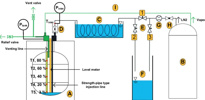
Fig. 1. Schematic diagram of the no-vent fill experiment apparatus; (A) Receiver tank, (B) LN
2supply unit, (C) LN
2bath heat exchanger, (D) inlet valve, (E) valve configuration with valve 1, 2, and 3, (F) LN
2Dewar, (G) Coriolis mass flow meter, (H) Globe valve, (I) pressurizing line.
72
Youngcheol Kim, Mansu Seo, Donggyu Yoo, and Sangkwon Jeong
of the receiver tank. The valve is immersed in the LN
2-filled cup structure to minimize the heat leak along the transfer line. The temperature sensor and the pressure sensor, which are the same type used in the receiver tank, are installed at the inlet of the valve to measure the inlet condition of the injected LN
2. The Coriolis mass flow meter measures the mass flow rate of the injected LN
2. The globe valve is installed at the inlet of the Coriolis mass flow meter to control the mass flow rate of the injected LN
2by adjusting valve opening. The valve configuration is used to precool the receiver tank and the transfer line before NVF experiment. No.1 and 2 valves are the cryogenic solenoid valve (Syntek, STH12C302T2S) for the rapid LN
2control.
Pressurizing line, a 1/4 inch copper tube, is used to apply the high pressurized nitrogen gas to the receiver tank when discharging of the LN
2from the receiver tank.
2.2. NVF experiment process and the conditions 2.2.1. Process of precooling the receiver tank
When the LN
2is injected into the receiver tank where the tank wall is approximately 300 K, the pressure in the receiver tank will increase rapidly and NVF should be failed because of the evaporation of the LN
2. Therefore, precooling process is necessary to prevent the rapid pressurization in the receiver tank. Cooling by a cryocooler or by evaporation cooling of a cryogens are used to precooling the receiver tank. In this research, the LN
2is injected into the receiver tank while the vent valve of the receiver tank is opened to precool the receiver tank. During the precooling process, No. 1 valve is opened while No. 2 and 3 valves are closed. The vented fill process is terminated when the tank is fully charged with the LN
2. When the receiver tank pressure becomes the atmospheric pressure, the receiver tank wall temperature reaches 77 K.
After that it is ready to drain the charged LN
2in the receiver tank. The vent valve of the receiver tank and No.1 valve are closed. The No.2 and 3 valves are opened to drain the LN
2from the receiver tank. The cold and high-pressurized nitrogen gas is injected through the pressurizing line. Since the outlet of the LN
2injection pipe is located 20 mm above from the bottom, most LN
2in the receiver tank is discharged passing through the LN
2injection pipe. The remained LN
2in the tank can be ignored because the volume, 0.27 L, corresponding to the height of 20 mm is negligible compared to the total tank volume, 9.2 L. During this draining process, the LN
2flows through No. 3 valve to maintain the transfer line at a low temperature. Therefore, this vented filling and draining procedure cools the receiver tank and overall transfer line before the main NVF experiment.
2.2.2. NVF experiment
After the LN
2is drained, the vent valve of the receiver tank is closed for NVF. The LN
2supply unit pressure is set at 5 bar (abs.). The valve opening of the cryogenic globe valve located in the forward direction of the Coriolis mass flow meter is set to make various mass flow rates for each NVF experiment. When No. 1 valve is opened and No. 2 and 3 valve are closed, NVF experiment begins. The NVF
A E
F G 1
2 3
A
D Tinlet
Toutlet Poutlet
Pintlet
B C
H
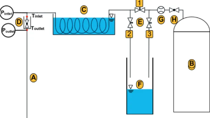
Fig. 2. Schematic diagram of the confirmation experiment for inlet condition apparatus; (A) A 2 m copper tube, (B) LN
2supply tank, (C) LN
2bath heat exchanger, (D) inlet valve, (E) valve configuration with valve 1, 2, and 3, (F) LN
2Dewar, (G) Coriolis mass flow meter, (H) Globe valve.
experiment is terminated when the receiver tank pressure becomes same as the LN
2supply unit pressure.
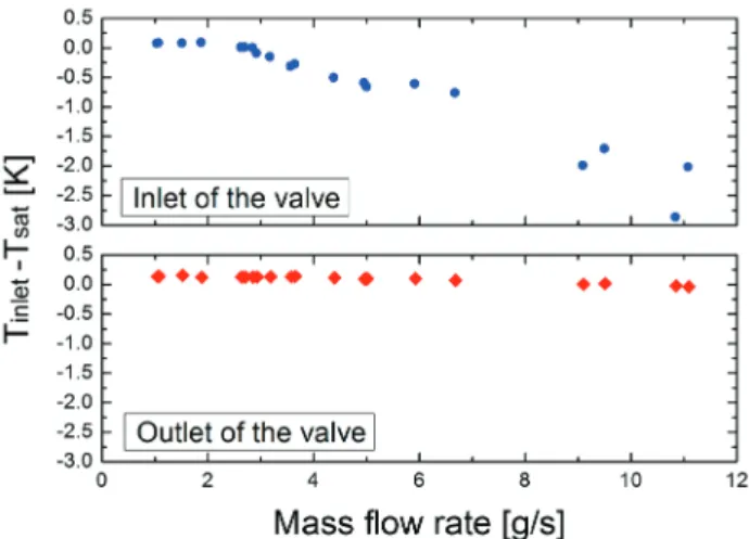
2.3. Confirmation experiment for the inlet condition The best way to measure the inlet condition of the injected LN
2is to install the sensors in the receiver tank with vacuum insulation. Since there is the geometric limit of the receiver tank, the sensors are installed in front of the inlet valve of the receiver tank.
Therefore, the exact state of the injected LN
2after the valve (D) is not measured. The additional experiment is performed to confirm the state of the LN
2after the inlet valve. For the inlet condition confirmation experiment, the experiment apparatus is fabricated, as shown in Fig. 2. The temperature and the pressure sensors are installed at the inlet and the outlet of the valve to measure the state of the LN
2which flows through the valve. A 2 m length copper tube is connected at the outlet of the valve instead of the receiver tank. The role of the copper tube is a pressure buffer to simulate the receiver tank in the NVF experiment.
The test is conducted similarly as NVF experiment with the various mass flow rates. The injected LN
2states in steady state are measured at the inlet and the outlet of the valve.
3. RESULTS 3.1. NVF experiment results
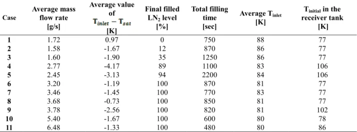
Table 1 summarizes the total 11 NVF experimental results with the various inlet mass flow rates. The average mass flow rate is the integrated average value of the fluctuated mass flow rate. The average value of T
inlet-T
satis the average values of temperature difference between the temperature measured at T
inletand the saturation temperature corresponding to the pressure measured at P
inletin Fig. 1. Final Liquid nitrogen (LN
2) filled level is the liquid level in the receiver tank measured by the capacitance-based level sensor. Total filling time is the duration of the NVF process. The average inlet temperature
73
Experimental investigation on No-Vent Fill (NVF) process using liquid Nitrogen
is the injected LN
2average temperature measured by the T
inletin Fig. 1. T
initialin the receiver tank is an average temperature of the vapor nitrogen in the receiver tank just before the NVF process.
As shown in the table 1, there is an obvious effect of the mass flow rate on the LN
2filled level. As the average mass flow rate is increased, final LN
2filled level is increased.
NVF achieves 100% final LN
2filled level when the average mass flow rate is greater than the certain value, 3.20 g/s. T
initialhas no effect on the NVF. Since the average value of T
inlet-T
satis negative value except the case 1, the whole injected LN
2is subcooled state. There is a tendency that the average inlet temperature is decreased as the mass flow rate is increased. Although the effect between the mass flow rate and the average inlet temperature is not intended initially, they are not separated in this experiment.
Internal energy and enthalpy are compared between the case 4 where the degree of subcooling is the largest case and the case 8 where the degree of subcooling is the smallest case using the commercial code REFPROP. The properties of the injected LN
2are calculated with the
parameters in Table 1. In the case 4, the internal energy is -110.65[kJ⁄kg]. The enthalpy is -110.29[kJ⁄kg]. In the case 8, the internal energy is -114.71[kJ⁄kg]. The enthalpy is -114.50[kJ⁄kg]. It is verified that the injected LN
2state of the case 8 has lower energy than the case 4 although the degree of subcooling of the case 8 is lower than the case 4.
Therefore, it can be estimated that the absolute temperature is more important than the degree of sub-cooling for the successful NVF.
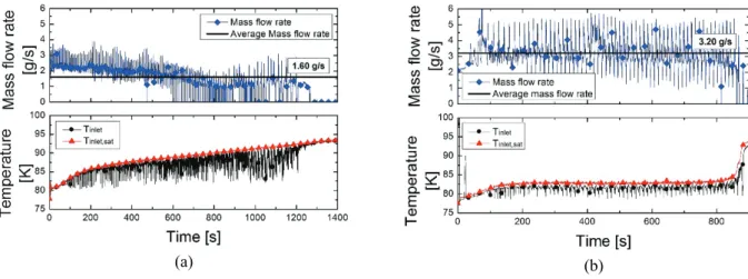
The average inlet temperature of the case 1 is 2 K higher than that of the case 2. In addition, the average value of T
inlet-T
satof the case 1 has a positive value, which means the state of the injected LN
2in the case 1 is superheated vapor.
Fig. 3 shows the history of T
inletand the saturation temperature corresponding to P
inletof the case 1 and 2. T
inletis fluctuated due to evaporation by the heat penetration and condensation in the LN
2bath heat exchanger. The temperature history in Fig. 3(a), excepting very short moments when T
inletis lower than T
inlet,sat, shows that T
inletis higher than T
inlet,satduring the whole time in the NVF, which means the superheated vapor is injected in the case 1.
TABLE I
S
UMMARY OF THE NO-
VENT FILL EXPERIMENTAL RESULTS. Case Average mass
flow rate [g/s]
Average value of [K]
Final filled LN
2level
[%]
Total filling time [sec]
Average T
inlet[K]
T
initialin the receiver tank
[K]
1 1.72 0.97 0 750 88 77
2 1.58 -1.67 12 870 86 77
3 1.60 -1.90 35 1250 86 77
4 2.77 -4.17 89 1100 83 106
5 2.45 -3.13 94 2200 84 106
6 3.20 -1.19 100 870 81 77
7 3.46 -1.45 100 770 83 77
8 3.68 -0.73 100 850 81 77
9 3.78 -2.56 100 820 81 102
10 5.40 -1.67 100 600 80 78
11 6.48 -1.33 100 480 80 86
.