392 https://doi.org/10.9713/kcer.2019.57.3.392
PISSN 0304-128X, EISSN 2233-9558
Pore Size Control of a Highly Transparent Interfacial Layer via a Polymer-assisted Approach for Dye-sensitized Solar Cells
Chang Soo Lee, Jae Hun Lee, Min Su Park and Jong Hak Kim†
Department of Chemical and Biomolecular Engineering, Yonsei University, 50, Yonsei-ro, Seodaemun-gu, Seoul, 03722, Korea (Received 3 February 2019; Received in revised form 21 March 2019; accepted 27 March 2019)
Abstract − A highly transparent interfacial layer (HTIL) to enhance the performance of dye-sensitized solar cells (DSSCs) was prepared via a polymer-assisted (PA) approach. Poly(vinyl chloride)-graft-poly(oxyethylene methacrylate) (PVC-g- POEM) was synthesized via atom-transfer radical polymerization (ATRP) and was used as a sacrificial template. The PVC-g-POEM graft copolymer induced partial coordination of a hydrophilic titanium isopropoxide (TTIP) sol-gel solu- tion with the POEM domain, resulting in microphase separation, and in turn, the generation of mesopores upon calcination.
These phenomena were confirmed using Fourier-transform infrared (FT-IR) spectroscopy, UV-visible light transmittance spec- troscopy, scanning electron microscopy (SEM), and X-ray diffraction (XRD) analysis. The DSSCs incorporating HTIL60/20 (consisting of a top layer with a pore size of 60 nm and a bottom layer with a pore size of 20 nm) exhibited the best overall conversion efficiency (6.36%) among the tested samples, which was 25.9% higher than that of a conventional blocking layer (BL). DSSC was further characterized using the Nyquist plot and incident-photon to electron conversion efficiency (IPCE) spectra.
Key words: Dye-sensitized solar cell (DSSC), Graft copolymer, Interfacial layer, Mesoporous TiO2, Microphase separation
1. Introduction
The energy crisis has become a major problem because of the shortage of fossil fuels and the enormous consumption of energy due to the significant growth of industry [1,2]. While such finite energy sources are easy to extract and process, and are used in almost all areas of daily life, their impending shortage will increase their cost and require more advanced extraction techniques. Therefore, the development of energy production technologies that utilize renew- able resources has become one of the most important tasks for the human race.
Photovoltaics, especially dye-sensitized solar cells (DSSCs), are materials that can produce photovoltaic and chemical energy by con- verting sunlight into electrons; specifically, sunlight can excite their electrons from the valance band to conduction band [3-5]. The big- gest advantage of DSSCs is their relatively low production cost com- pared with silicon solar cells. However, their overall energy conver- sion efficiency is not yet high enough to make them commercially viable. Therefore, enhancement of their conversion efficiency is the main challenge to be overcome for the adoption DSSCs.
Many studies have investigated methods to enhance the perfor- mance of DSSCs via modification of the physical or chemical prop- erties of their components, e.g., electron conductivity, light scattering
ability, and light transmission into the photoelectrode, among others.
In particular, the enhancement of light transmission can be easily achieved by smoothing the surface of the fluorine-doped tin oxide (FTO) glass substrates used in DSSCs via coating the glass with an interfacial layer (IL) [6-8]. However, thick, dense ILs have a nega- tive effect on the adsorption of the dye molecules. Therefore, the preparation of mesoporous TiO2 ILs has been studied as a method to enhance both the light transmittance and the adsorption of dye mole- cules; however, its small pore size makes good penetration of the electrolyte difficult [9].
Polymer templates have often been used to induce micro- or mes- opores in the TiO2 film via phase separation behavior in the solution state, resulting in the generation of pores in the TiO2 membrane in the hydrophobic domain after the calcination of the polymer/TiO2 precursor composites [10] Graft copolymers have attracted wide interest due to their good solubility for the preparation of solutions or membranes, controllable viscosity, phase-separation behavior, and low thermal degradation temperature, which are an important prop- erties for polymer templates [11-15]. Amphiphilic graft copolymers could play a pivotal role in constructing TiO2 scaffolds with an inter- connected morphology as a consequence of the connected hydro- philic domains of the graft copolymer.
Herein, we report a facile, polymer-assisted (PA) approach to the preparation of organized mesoporous (OM) highly transparent inter- facial layers (HTILs) by utilizing an amphiphilic graft copolymer as a sacrificial template, which allows facile control of the pore size.
Amphiphilic graft copolymers are advantageous in terms of their synthesis cost compared to block copolymers, their micro-phase sep- aration behavior, and their superior polydispersity compared to random
†To whom correspondence should be addressed.
E-mail: [email protected]
‡This article is dedicated to Prof. Yong-Gun Shul on the occasion of his retirement from Yonsei University.
This is an Open-Access article distributed under the terms of the Creative Com- mons Attribution Non-Commercial License (http://creativecommons.org/licenses/by- nc/3.0) which permits unrestricted non-commercial use, distribution, and reproduc- tion in any medium, provided the original work is properly cited.
copolymers. We synthesized poly(vinyl chloride)-graft-poly(oxyeth- ylene methacrylate) (PVC-g-POEM) via an atom-transfer radical polymerization (ATRP) process. The synthesized PVC-g-POEM exhib- ited a unique ability, wherein hydrophilic titanium isopropoxide (TTIP) sol-gel could partially coordinate into the hydrophilic POEM domain as the result of dipole-dipole interactions. Therefore, after the anneal- ing process we obtained HTILs with a large pore size (> 20 nm) that could be easily controlled by simple variation of the POEM content.
The DSSC containing HTIL60/20, which was composed of a top layer with a large pore size and bottom layer with a small pore size, achieved an overall conversion efficiency of 6.36% due to its supe- rior light transmittance, good electrolyte penetration through its large pores, and the electron recombination suppression of the bottom layer with small pores.
2. Experimental Section
2-1. Materials
Poly(vinyl chloride) (PVC, Mn = 55,000), poly(ethylene glycol) methyl ether methacrylate (poly(oxyethylene methacrylate), POEM, Mn = 500), copper (I) chloride (CuCl, 99%), 1,1,4,7,10,10-hexam- ethyltriethylenetetramine (HMTETA, 97%), titanium (IV) isopropox- ide (TTIP, 97%), hydrochloric acid (HCl, ACS reagent, 37%), titanium diisopropoxide bis(acetylacetonate) (75 wt% in isopropanol), chlo- roplatinic acid hexahydrate (H2PtCl6), 1-methyl-3-propylimidazolium iodide (MPII), poly(ethylene glycol) (PEG, Mn = 10,000), iodine (I2, 99%), and lithium iodide (LiI, 99.9%) were all purchased from Aldrich and used as received without further purification. Tetrahydrofuran (THF), N-methyl pyrrolidone (NMP), butanol, methanol (MeOH), isopropanol (IPA), absolute ethanol (EtOH, 99.99%), and acetonitrile were purchased from J.T. Baker. Deionized water (>18 MΩ m) was obtained using a water purification system made by the Millipore Corporation. Ruthenium dye (535-bisTBA, N719) was purchased from Solaronix, Switzerland, and TiO2 commercial colloidal paste (Dye- sol paste, 18NR-T) was purchased from GreatCell Solar (formally called Dyesol). The FTO conducting glass substrate (TEC8, 8 Ω/sq, thickness 2.3 mm) was purchased from Pilkington, France.
2-2. Preparation of the PVC-g-POEM graft copolymer template PVC-g-POEM was prepared according to previous reports in the literature, as shown in Scheme 1 [16-18]. Briefly, 6 g of PVC was dissolved in NMP to prepare a transparent solution. Then, 9 g (PVC- g-POEM 1:1.5) or 24 g (PVC-g-POEM 1:4) of POEM, 0.1 g of CuCl, and 0.23 ml of HMTETA were added to the solution, which was then purged with N2 for 1 h under mild stirring. The mixture was reacted at 90 °C for 24 h to achieve polymerization. After the polymeriza- tion process, the resultant product was precipitated and washed sev- eral times in excess methanol. An additional purification process was performed in which the polymer was dissolved in THF and re-pre- cipitated in methanol. The final product was dried in a conventional oven at 50 °C and then in a vacuum oven at room temperature.
2-3. Fabrication of the organized mesoporous (OM) TiO2 films The OM TiO2 film was fabricated via a polymer-assisted (PA) approach based on our previous report [18]. A 3 wt% PVC-g-POEM solution was prepared by dissolving the polymer in THF. Separately, a TTIP sol-gel solution was prepared by adding HCl and deionized water to TTIP under vigorous stirring for 30 min in a TTIP:HCl:H2O volume ratio of 2:1:1. The TTIP sol-gel solution was added to the 3 wt% PVC-g-POEM solution and allowed to stabilize at room tem- perature for 6 h. The final solution was cast on FTO glass via spin- coating at 1500 rpm for 20 s and then annealed at 450 °C for 30 min under ambient conditions to yield the OM TiO2 film.
2-4. Preparation of the highly transparent interfacial layers (HTILs)
The highly transparent interfacial layers (HTILs) for the DSSCs were prepared through the deposition of OM TiO2 layers on FTO glass via sequential spin-coating and annealing methods. Before preparation of the HTILs, the FTO glass was washed with ethanol, acetone, and ethanol under ultrasonication for 30 min each. To tune the pore size of the OM TiO2 films, different graft copolymer templates were employed: 1:1.5 PVC-g-POEM was used to obtain a pore size of 60 nm (HTIL60), and 1:4 PVC-g-POEM was used to obtain 20 nm pore (HTIL20) thin films. To prepare HTIL60, which had an average pore size of 60 nm, the PVC-g-POEM 1:1.5/TTIP sol-gel hybrid solution was deposited on the FTO glass and annealed at 450 °C for 30 min. For HTIL20, PVC-g-POEM 1:4 was employed instead of PVC-g-POEM 1:1.5. To produce HTIL20/60 and HTIL60/20, the two films were sequentially deposited on the FTO glass through the spin- coating and annealing method. To prepare a control sample, a solution of titanium diisopropoxide bis(acetylacetonate) in butanol was spin- coated on the FTO glass and annealed at 450 °C for 30 min to prepare a conventional blocking layer (BL).
2-5. Fabrication of DSSCs using the HTILs
The photoelectrodes of the DSSCs were fabricated using Scheme 1. Synthesis of PVC-g-POEM via the ATRP process.
commercially available 18NR-T Dyesol paste. The paste was directly deposited on the HTILs or the conventional BL via the doctor-blade technique using 50 µm thick 3M magic tape as a spacer to form a 7 µm nanocrystalline (NC) TiO2 layer. The photoelectrodes were dried in a conventional oven at 50 and 70 °C for 1 h each, followed by thermal treatment at 450 °C for 30 min to remove residual organics.
The photoelectrodes were then scraped with a razor blade to remove the excess active material, leaving behind an active area of 0.4
× 0.4 cm2. They were then immersed in a 10-4 M ruthenium N719 dye solution in ethanol at 50 °C for 2 h in dark room conditions to deposit the dye molecules on the surface of the TiO2 film-coated photoelectrodes. Subsequently, the photoelectrodes were washed with absolute ethanol at room temperature to remove any residual non- adsorbed dye molecules. To fabricate the counter electrode, a 4 wt%
H2PtCl6 solution in isopropanol was spin-coated on an FTO glass substrate, followed by a thermal treatment at 450 °C to form Pt nanoparticles. A polymeric nanogel solution was employed as the electrolyte of the quasi-solid-state DSSCs. To prepare the nanogel, PEG, LiI, MPII, and I2 were dissolved in acetonitrile at room temperature; both a low and a high concentration (2 wt% and 10 wt%) solution were prepared and cast on the electrodes uniformly. First, the 2 wt% nanogel electrolyte solution was cast onto the dye-absorbed photoelectrode and evaporated slowly to induce proper penetration of the electrolyte into the porous structure. Secondly, the 10 wt%
nanogel electrolyte was deposited on both the photo and counter electrodes, and both electrodes were pressed together to prepare a thin electrolyte layer and to achieve better contact between the electrolyte and electrodes through slow evaporation. The cells were further dried in a vacuum oven for one day to completely evaporate the residual solvents and then sealed with an epoxy resin to prevent separation of the electrodes.
2-6. Characterization
Fourier-transform infrared spectroscopy (FT-IR, Spectrum 100, Perkin Elmer, USA) was employed to identify the chemical bonds of the reactants and products. The surface and cross-sectional morphol- ogies of the HTILs were observed using field emission scanning elec- tron microscopy (FE-SEM, SUPRA 55VP, Carl Zeiss, Germany) at an accelerating voltage of 10 kV. UV-visible light transmittance spec- tra were measured in the wavelength region from 300 to 800 nm using a UV-visible spectrophotometer (S-3100, Scinco, South Korea). The thickness and refractive index data were collected using ellipsome- try (Alpha-SE) and analyzed using the instrument software (Complete EASE software package, J.A. Woollam, USA). The crystallinity of the HTIL on the FTO glass substrate was measured using X-ray diffrac- tion (XRD, Miniflex, Rigaku, Japan) at a scan rate of 5° min-1 from 20 to 70°. Transmission electron microscopy (TEM, Talos L120C, FEI, Czech Republic) was utilized to identify the phase-separation behavior of the polymer by casting the polymer solution onto a Cu/C TEM grid. General DSSC performance data, such as the current den- sity-voltage (J-V) curve, electrochemical impedance spectra (EIS),
and incident photon-to-current conversion efficiency (IPCE), were obtained using a solar simulator (model 11000, ABET Technologies, USA) equipped with a 1000 W Xenon lamp (Oriel, 91193) under AM 1.5 (100 mW cm-2) light illumination and a Keithley model 2400 SourceMeter Unit and a frequency response analyzer (Compactstat, IVIUM Technologies, Netherlands). The light intensity of the solar simulator was calibrated using a certified reference silicon solar cell (Fraunhofer Institute for Solar Energy System, Mono-Si þ KG filter, Certificate No. C-ISE269) with an active area of 4 × 4 cm2. During the measurement of the DSSCs, the devices were covered with a mask to block additional light from entering through the side region.
3. Results and Discussion
3-1. Preparation of the HTILs via PA approach
The amphiphilic graft copolymer PVC-g-POEM was synthesized via ATRP, as shown in Scheme 1. The synthesis of the PVC-g- POEM graft copolymer was carried out using CuCl and HMTETA as the catalyst and ligand, respectively. The FT-IR spectra of PVC in Figure 1 shows a strong absorption band at 608 cm-1 corresponding to the C-Cl bond. In the case of POEM, three representative bands were observed at 1717, 1637, and 1098 cm-1, corresponding to the C=O, C=C, and C-O-C bonds, respectively [18]. After polymeriza- tion, absorption bands appeared at 1099 and 608 cm-1, demonstrating the successful synthesis of PVC-g-POEM. Notably, the absorption band of the C=O bonds of POEM shifted from 1717 to 1727 cm-1 after polymerization. This was attributed mainly to the reduced d-spacing between the POEM domains, which resulted in a repulsive force
Fig. 1. FT-IR spectra of PVC, POEM, PVC-g-POEM 1:1.5, and PVC-g-POEM 1:4.
between C=Oδ- groups (C=Oδ-…δ-O=C), which shortened or strengthened the C=O bond in PVC-g-POEM compared with that in POEM. This phenomenon could be explained using Hooke’s law as follows [19]:
where ν is the wavenumber of the absorbance band, k is a constant, f is the force constant of the chemical bond, and m is the mass of the atoms involved in the bond.
Scheme 2a illustrates the process used to prepare the HTIL with a PVC-g-POEM graft copolymer template via the PA approach. The hydrophilic TTIP sol-gel preferably coordinated with the hydrophilic POEM domain due to the dipole-dipole interaction between Ti4+ and the oxygen atoms in the C-Oδ--C/C=Oδ- groups. Moreover, the small quantity of deionized water in the TTIP sol-gel solution induced microphase separation into core-shell structures composed of PVC cores and POEM/TTIP shells. After the calcination of the PVC-g- POEM/TTIP sol-gel hybrid mixture, OM TiO2 was obtained, as the PVC core was thermally decomposed to generate the mesopores in the TiO2 nanostructure, which formed from the POEM/TTIP domains.
Interestingly, the average pore size of OM TiO2 could be easily tuned by simply modifying the content of POEM relative to that of PVC.
When PVC-g-POEM 1:1.5 was employed as the sacrificial template, we obtained an OM TiO2 film with an average pore size of 60 nm, and for PVC-g-POEM 1:4, a pore size of 20 nm was obtained.
Therefore, the refractive index of the OM TiO2 film was easily controlled by using different POEM content in PVC-g-POEM, which in turn changed the average pore size. We fabricated four kinds of HTILs: 1) HTIL20 (an OM TiO2 film with 20 nm pore size), 2) HTIL60 (an OM TiO2 film with 60 nm pore size), 3) HTIL20/60 (an OM- TiO2 film with 20 nm pores coated onto another OM-TiO2 film with 60 nm pores), and 4) HTIL60/20 (an OM-TiO2 film with 60 nm pores on a 20 nm pore film).
3-2. Structure and morphology
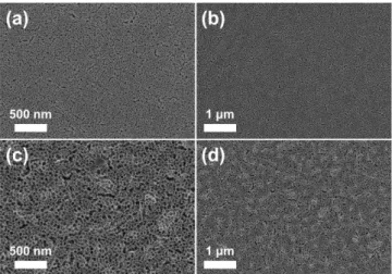
FE-SEM images were obtained to determine the morphology, pore size, and thickness of the HTIL samples (Fig. 2 and Fig. 3). First, the HTIL20 and HTIL60 monolayers coated on FTO glass substrates were characterized. In the resulting FE-SEM images, OM TiO2 nanostructures with average pore sizes of approximately 20 nm and 60 nm were clearly observed. The different average pore sizes of the HTIL20 and HTIL60 samples were also observed in the TEM images in Fig. 4, along with their different phase separation behavior. Micro- phase separation was observed, with PVC (dark) and POEM (bright) regions; this different brightness was due to the difference in elec- tron density between PVC and POEM, especially that of the chlorine group (-Cl) in PVC. Specifically, PVC-g-POEM 1:1.5 exhibited more dark regions compared to PVC-g-POEM 1:4, which resulted in its having a larger pore size after the calcination of PVC-g-POEM to generate the pores in the PVC region. Moreover, the low-magnifica-
v k f
m----
=
Scheme 2. Schematic illustration of the preparation of highly transparent interfacial layers (HTILs) for DSSCs via a polymer-assisted (PA) approach, and (b) cross-sectional schematic illustrations of HTIL20, HTIL60, HTIL20/60, and HTIL60/20.
tion FE-SEM images of both HTIL20 and HTIL60 demonstrated that a uniform, defect-free interfacial layer was coated on the FTO glass substrate (Fig. 2b and d). Subsequently, layer-by-layer coating of HTIL20 and HTIL60 was then conducted to prepare HTIL20/60 and HTIL60/20 bilayers, and surface FE-SEM images of the bilayers were obtained, as shown in Fig. 3. A small portion of the mesopores formed a worm-like morphology. This change in the pore morphol- ogy was mainly attributed to the highly porous bottom layer, which could allow slight infiltration of the PVC-g-POEM/TTIP sol-gel hybrid solution after casting on the HTIL monolayer. However, according to the low-magnification images in Fig. 3b and d, no significant defects, cracks, or fluctuations in the surface were observed, implying that uni- form HTIL20/60 and HTIL60/20 bilayers were successfully con- structed on the FTO glass substrate.
Moreover, cross-sectional FE-SEM images and photograph of HTILs were also obtained to determine the thickness and confirm the uniformity of HTILs (Fig. 5). When HTIL20 was deposited on HTIL60 to prepare HTIL20/60, the resulting HTIL20 layer was thin- ner than that of bare HTIL20. This might be attributed to slight pene-
tration of the casting solution into the bottom layer, i.e., HTIL60.
Therefore, the thickness of the top and bottom layers of HTIL20/60 was calculated to be 170 and 250 nm, respectively (Fig. 5a and b).
HTIL60/20 exhibited similar behavior to HTIL20/60, with a thick- ness of 120 and 270 nm for the top (HTIL20) and bottom (HTIL60) layers, respectively. Notably, the thicknesses of the bottom layers were the same as those of the HTIL20 and HTIL60 monolayers alone, according to Fig. 6. The total thickness of the HTIL20/60 and HTIL60/20 bilayers was optimized to approximately 400 nm to investi- gate the exact performance of the resulting DSSCs, and photographs of the samples were taken to identify the transparency of each of the HTILs with the naked eye Fig. 5(e). HTIL60/20 clearly exhibited the best transparency; overall, the transparency of the samples followed the order HTIL60/20 > HTIL20/60 > HTIL60 > HTIL20 (Fig. 5e).
UV-visible light transmittance (UV-T) spectra were measured to Fig. 2. FE-SEM surface images of (a), (b) HTIL20 and (c), (d) HTIL60
on a FTO glass substrate.
Fig. 3. FE-SEM surface images of (a), (b) HTIL60/20 and (c), (d) HTIL20/60 on a FTO glass substrate.
Fig. 4. TEM images of (a) PVC-g-POEM 1:1.5 and (b) PVC-g- POEM 1:4 in THF/HCl/H2O.
Fig. 5. Cross-sectional FE-SEM images of (a), (b) HTIL20/60 and (c), (d) HTIL60/20, and (e) a photograph of the HTIL sam- ples on FTO glass.
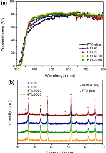
confirm the actual transmittance of HTILs, as shown in Fig. 7a. All of the HTILs exhibited much better transmittance than bare FTO glass due to the interfacial coating of the uneven FTO surface with the uniform OM TiO2 nanostructured films. The transmittance of the monolayer HTIL20 and HTIL60 samples at 400 nm was 70.7 and 67.1%, respectively. The higher transmittance of HTIL20 than HTIL60 was mainly due to its dense TiO2 layer, which formed a more uni- form, flat surface, as well as its more uniform refractive index com- pared to the more porous HTIL60. However, when the layer-by-layer method was applied, the transmittance of the HTIL60/20 and HTIL20/
60 samples at a wavelength of 400 nm increased up to 74.9 and 75.5%, respectively. Although the enhancement of transmittance of HTIL20/60 was much higher than HTIL60/20, over the entire wave- length region, HTIL20/60 was generally higher than that of HTIL20/
60. Moreover, XRD measurement was employed to determine the crystallinity of the HTILs on FTO glass (Fig. 7b). The FTO glass peaks were clearly observed in all the HTILs; however, HTIL20/60 and HTIL60/20 also exhibited peaks corresponding to the anatase phase of TiO2 [20-22]. The anatase phase is well-known to have a higher specific surface area and better adsorption ability for N719 dye than the rutile phase; therefore, the formation of the anatase phase is an important criteria for interfacial TiO2 layers in DSSCs [23-25].
3-3. DSSC performance
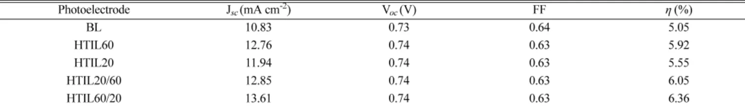
The HTILs were further coated with commercially available Dye- sol 18NR-T paste to prepare a 7 µm thick nanocrystalline TiO2 layer to fabricate photoelectrodes, and then assembled into DSSCs to eval- uate their performance (Fig. 8). Compared to a control DSSC con- taining a conventional BL, the DSSCs containing an HTIL interfacial layer showed dramatically enhanced overall efficiency, especially in terms of the short-circuit current density (Jsc). The HTIL60/20 DSSC exhibited the highest Jsc of 13.621 mA cm-2, which was 25.6% higher than that the of the conventional BL DSSC (Table 1). Interestingly, the open circuit voltage (Voc) was quite similar for all of the samples, as they all used the same nanocrystalline photoelectrodes and exhib-
ited excellent suppression of charge recombination from the FTO glass to the NC TiO2 layer. This was supported by the Nyquist plot in Fig. 8b, in which the HTIL DSSCs exhibited better solution resis- tance (Rs), charge transfer resistance (Rct), and Warburg impedance (Zd) than the BL DSSC. Although the overall resistance of the HTIL DSSCs was much lower than that of the BL DSSC, as the recombi- nation of electrons from FTO to the electrolyte or TiO2 was not fully suppressed due to their porous morphology, the Voc values of the HTIL DSSCs neither increased nor decreased. In particular, the over- all efficiency (η) of the HTIL60/20 DSSC (6.36%) was dramatically increased by 25.9% compared to that of the BL DSSC (5.05%). The HTIL60/20 DSSC showed better performance than the HTIL20/60 DSSC (6.05%), mainly due to the following two considerations. First, the average pore size of the top layer of HTIL60/20 was much larger than that of HTIL20/60, which allowed the nanogel electrolyte to bet- ter penetrate the interfacial layer. Second, the gradual decrease in the refractive index from FTO to NC TiO2 could result in better transmit- tance due to the anti-reflection phenomenon, resulting in better utilization of light to excite electrons in the N719 dye molecules. Specifically, this explanation was supported by the IPCE and normalized IPCE spectra in Fig. 8c and d. The HTIL60/20 DSSC showed the best Fig. 6. Cross-sectional FE-SEM images of (a), (b) HTIL20 and (c),
(d) HTIL60.
Fig. 7. (a) UV-visible light transmittance spectra and (b) X-ray dif- fraction patterns of the HTILs on FTO glass.
overall IPCE performance among the DSSCs. Particularly, the nor- malized IPCE spectra implied that HTIL60/20 and HTIL20/60 were more favorable in terms of allowing light to penetrate into the NC TiO2 layer compared to the monolayers (HTIL20 and HTIL60) in the wavelength region from 350 to 400 nm. These results were in good agreement with the UV-T spectra, which showed that the multi-layer HTILs exhibited better relative light transmission in that region.
Therefore, the fabrication of an interfacial layer with an upper layer with large pores and a lower layer with small pores played a pivotal role in simultaneously achieving electrolyte permeation and prevent- ing electron recombination.
4. Conclusion
We developed a facile, polymer-assisted approach to a prepare
highly transparent interfacial layers for DSSCs. The amphiphilic graft copolymer PVC-g-POEM played a pivotal role in the fabrication of organized mesoporous TiO2 with a large average pore size (> 20 nm) via selective coordination of the hydrophilic TTIP sol-gel with the POEM domain. We easily controlled the resulting pore size of the OM TiO2 film after calcination through simple modification of the POEM content. The layer-by-layer coating of HTIL20 and HTIL60 resulted in better light transmittance in the 350 to 450 nm wavelength region, which resulted in better light utilization by the N719 dye. The DSSC containing HTIL60/20 achieved the best ICPE performance of 6.36%, which was 25.9% higher than that of the conventional BL DSSC (5.05%). Its enhanced efficiency was attributed to its structure, which consisted of a top layer with large pores that induced the facile pene- tration of the polymer electrolyte, and a bottom layer with small pores to suppress charge recombination.
Fig. 8. (a) Current density-voltage (J-V) curves, (b) Nyquist plots, (c) incident photon-to-current conversion efficiency (IPCE), and (d) normalized IPCE of the HTIL-containing DSSCs.
Table 1. Photovoltaic parameters of the DSSCs containing the HTILs and the conventional BL
Photoelectrode Jsc (mA cm-2) Voc (V) FF η (%)
BL 10.83 0.73 0.64 5.05
HTIL60 12.76 0.74 0.63 5.92
HTIL20 11.94 0.74 0.63 5.55
HTIL20/60 12.85 0.74 0.63 6.05
HTIL60/20 13.61 0.74 0.63 6.36
Acknowledgments
This work was supported by a National Research Foundation (NRF) grant funded by the Ministry of Science, ICT and Future Planning (NRF-2017R1D1A1B06028030 and NRF-2018M3A7B4071535).
References
1. Barnham, K. W. J., Mazzer, M. and Clive, B., “Resolving the Energy Crisis: Nuclear or Photovoltaics?,” Nat. Mater., 5, 161- 164(2006).
2. Commoner, B., “Poverty of Power: Energy and the Economic Crisis,” Knopf Doubleday Publishing Group, New York City, NY(2015).
3. Law, M., Greene, L. E., Johnson, J. C., Saykally, R. and Yang, P., “Nanowire Dye-sensitized Solar Cells,” Nat. Mater., 4(6), 455 (2005).
4. Hagfeldt, A., Boschloo, G., Sun, L., Kloo, L. and Pettersson, H.,
“Dye-sensitized Solar Cells,” Chem. Rev., 110(11), 6595-6663(2010).
5. O'regan, B. and Grätzel, M., “A Low-cost, High-efficiency Solar Cell Based on Dye-sensitized Colloidal TiO2 Films,” Nature, 353(6346), 737(1991).
6. Kim, S. R., Parvez, M. K. and Chhowalla, M., “UV-reduction of Graphene Oxide and Its Application as an Interfacial Layer to Reduce the Back-transport Reactions in Dye-sensitized Solar Cells,” Chem. Phys. Lett., 483(1-3), 124-127(2009).
7. Kim, Y. J., Lee, Y. H., Lee, M. H., Kim, H. J., Pan, J. H., Lim, G.
I., Choi, Y. S., Kim, K., Park, N.-G. and Lee, C., “Formation of Efficient Dye-sensitized Solar Cells by Introducing an Interfa- cial Layer of Long-range Ordered Mesoporous TiO2 Thin Film,”
Langmuir, 24(22), 13225-13230(2008).
8. Ahn, S. H., Jeon, H., Son, K. J., Ahn, H., Koh, W.-G., Ryu, D. Y.
and Kim, J. H., “Efficiency Improvement of Dye-sensitized Solar Cells Using Graft Copolymer-templated Mesoporous TiO2 Films as an Interfacial Layer,” J. Mater. Chem., 21(6), 1772-1779(2011).
9. Park, J. T., Prosser, J. H., Ahn, S. H., Kim, S. J., Kim, J. H. and Lee, D., “Enhancing the Performance of Solid-State Dye-Sensi- tized Solar Cells Using a Mesoporous Interfacial Titania Layer with a Bragg Stack,” Adv. Funct. Mater., 23(17), 2193-2200(2013).
10. Ahmad, R., Kim, J. K., Kim, J. H. and Kim, J., “In-situ TiO2 Forma- tion and Performance on Ceramic Membranes in Photocatalytic Membrane Reactor,” Membr. J., 27(4), 328-335(2017).
11. Kim, N. U., Park, B. J., Park M. S. and Kim, J. H., “Effect of PVP on CO2/N2 Separation Performance of Self-crosslinkable P(GMA-g-PPG)-co-POEM) Membranes,” Membr. J., 28(2), 113- 120(2018).
12. Park, B. J., Kim, N. U., Park, J. T. and Kim, J. H., “Synthesis, Characterizations and Gas Separation Property of PBEM-PMMA- POEM Terpolymer Membranes,” Membr. J., 28(2), 121-128(2018).
13. Patel, R., Park, J. T., Park, M. S. and Kim, J. H., “Synthesis, Mor-
phology and Permeation Properties of poly(dimethyl siloxane)- poly(1-vinyl-2-pyrrolidinone) Comb Copolymer,” Membr. J., 27(6), 499-505(2017).
14. Son, T. Y., Jo, J. W., Kim, J. H., Kim, T. H., Tocci, E. and Nam, S. Y., “Preparation and Gas Characterization of Poly(phenylene oxide) Containing Imidazolium,” Membr. J., 27(6), 528-535(2017).
15. Shin, J. E. and Park, H. B., “Gas Separation Properties of Micro- porous Carbon Membranes Containing Mesopores,” Membr. J., 28(4), 221-232(2018).
16. Roh, D. K., Park, J. T., Ahn, S. H., Ahn, H., Ryu, D. Y. and Kim, J. H., “Amphiphilic poly(vinyl chloride)-g-poly(oxyethylene methac- rylate) Graft Polymer Electrolytes: Interactions, Nanostructures and Applications to Dye-sensitized Solar Cells,” Electrochim. Acta, 55(17), 4976-4981(2010).
17. Koh, J. H., Lee, K. J., Seo, J. A. and Kim, J. H., “Amphiphilic Poly- mer Electrolytes Consisting of PVC-g-POEM Comb-like Copo- lymer and LiCF3SO3,” J. Polym. Sci. B.: Polym. Phys., 47(15), 1443- 1451(2009).
18. Ahn, S. H., Koh, J. H., Seo, J. A. and Kim, J. H., “Structure Control of Organized Mesoporous TiO2 Films Templated by Graft Copoly- mers for Dye-sensitized Solar Cells,” Chem. Commun., 46(11), 1935- 1937(2010).
19. Burke, J. T., “IR Spectroscopy or Hooke's Law at the Molecular Level - A Joint Freshman Physics-Chemistry Experience,” J. Chem.
Educ., 74(10), 1213(1997).
20. Feng, X., Zhu, K., Frank, A. J., Grimes, C. A. and Mallouk, T.
E., “Rapid Charge Transport in Dye-sensitized Solar Cells Made from Vertically Aligned Single-crystal Rutile TiO2 Nanowires,”
Angew. Chem., 124(11), 2781-2784(2012).
21. Liu, B. and Aydil, E. S., “Growth of Oriented Single-crystalline Rutile TiO2 Nanorods on Transparent Conducting Substrates for Dye-sensitized Solar Cells,” J. Am. Chem. Soc., 131(11), 3985- 3990(2009).
22. Wang, H., Bai, Y., Wu, Q., Zhou, W., Zhang, H., Li, J. and Guo, L., “Rutile TiO2 Nano-branched Arrays on FTO for Dye-sensi- tized Solar Cells,” Phys. Chem. Chem. Phys., 13(15), 7008-7013 (2011).
23. Yang, J.-S., Liao, W.-P. and Wu, J.-J., “Morphology and Interfacial Energetics Controls for Hierarchical Anatase/rutile TiO2 Nano- structured Array for Efficient Photoelectrochemical Water Split- ting,” ACS Appl. Mater. Interfaces, 5(15), 7425-7431(2013).
24. Li, G., Richter, C. P., Milot, R. L., Cai, L., Schmuttenmaer, C.
A., Crabtree, R. H., Brudvig, G. W. and Batista, V. S., “Synergistic Effect Between Anatase and Rutile TiO2 Nanoparticles in Dye- sensitized Solar Cells,” Dalton Trans., 45, 10078-10085(2009).
25. Baek, I. C., Vithal, M., Chang, J. A., Yum, J.-H., Nazeeruddin, M. K., Grätzel, M., Chung, Y.-C. and Seok, S. I., “Facile Prepa- ration of Large Aspect Ratio Ellipsoidal Anatase TiO2 Nanoparticles and Their Application to Dye-sensitized Solar Cell,” Electrochem.
Commun., 11(4), 909-912(2009).