184
|
wileyonlinelibrary.com/journal/etrij ETRI Journal. 2021;43(2):184–196.1
|
INTRODUCTION
The shallow underwater acoustic (UWA) channel has been considered one of the most difficult channels for wireless communication because of several shortcomings, such as low data rate, bandwidth limitation, high multipath interference, major Doppler shifts, and severe fading [1–3]. The main mo-tivation to use sound waves over electromagnetic signals is due to the relatively lower attenuation in the underwater envi-ronment [4]. A UWA channel has poor communication qual-ity and high propagation delay; consequently, the bit error
rate (BER) is increased [5]. However, the channel coding techniques can significantly decrease BER at the expense of some bandwidth loss of communication.
The channel coding techniques add a redundancy of useful bits for data protection in a noisy channel [6]. The following commonly employed channel coding techniques in wireless communication have been thoroughly investigated consider-ing UWA: low-density parity check (LDPC) code, convolution code (CC), Reed-Solomon (RS) code, and turbo code. Seo and others [7] assessed the effectiveness of the RS code and CC in the context of a UWA fading channel. The simulated findings of
O R I G I N A L A R T I C L E
Filter orthogonal frequency-division multiplexing scheme based
on polar code in underwater acoustic communication with
non-Gaussian distribution noise
Mustafa Sami Ahmed
1|
Nor Shahida Mohd Shah
2|
Yasin Yousif Al-Aboosi
3|
Mohammed S. M. Gismalla
1|
Mohammad F. L. Abdullah
1|
Yasir Amer Jawhar
1|
Mohammed Balfaqih
41Department of Communication Engineering, Universiti Tun Hussein Onn Malaysia, Johor, Malaysia
2Faculty of Engineering Technology, Universiti Tun Hussein Onn Malaysia, Johor, Malaysia 3Faculty of Engineering, University of Mustansiriyah, Baghdad, Iraq 4Department of Computer and Network Engineering, University of Jeddah, Jeddah, Saudi Arabia
Correspondence
Mustafa Sami Ahmed, Department of Communication Engineering, Universiti Tun Hussein Onn Malaysia, Johor, Malaysia. Email: [email protected]
Funding information
This research was funded by the Ministry of Higher Education Malaysia under Fundamental Research Grant Scheme (FRGS) Vot No. K096 and partially sponsored by Universiti Tun Hussein Onn Malaysia.
The research domain of underwater communication has garnered much interest among researchers exploring underwater activities. The underwater environment dif-fers from the terrestrial setting. Some of the main challenges in underwater commu-nication are limited bandwidth, low data rate, propagation delay, and high bit error rate (BER). As such, this study assessed the underwater acoustic (UWA) aspect and explored the expression of error performance based on t-distribution noise. Filter orthogonal frequency-division multiplexing refers to a new waveform candidate that has been adopted in UWA, along with turbo and polar codes. The empirical out-comes demonstrated that the noise did not adhere to Gaussian distribution, whereas the simulation results revealed that the filter applied in orthogonal frequency-divi-sion multiplexing could significantly suppress out-of-band emisfrequency-divi-sion. Additionally, the performance of the turbo code was superior to that of the polar code by 2 dB at BER 10−3.
K E Y W O R D S
F-OFDM, orthogonal frequency-division multiplexing, polar code, t-distribution, turbo code, underwater acoustic
This is an Open Access article distributed under the term of Korea Open Government License (KOGL) Type 4: Source Indication + Commercial Use Prohibition + Change Prohibition (https://www.kogl.or.kr/info/license.do#05-tab).
RS code and CC demonstrated better performance for selective and nonselective frequency fading, respectively. Another study tested various types of error correction schemes, including CC and RS block codes, on a UWA channel [8]. The results revealed that both RS code and CC could reduce BER to 10−2−10−4, al-though CC displayed better quality than the RS code. Huang and others [9] proposed nonbinary LDPC codes in multicarrier UWA communications. Their findings showed that the scheme could hit a zero BER with real data when compared to a large BER via CC. This is because the LDPC code has greater error correction capability than CC does, despite the drawbacks of the former [5,10]. In the context of a very shallow Singaporean water channel, a study assessed coded orthogonal frequency-di-vision multiplexing (OFDM) based on non-Gaussian noise [2]. Here, two convolution codes were applied between each code interleave, whereas the Viterbi algorithm was used at the re-ceiver to decode CC. Consequently, the BER performance of OFDM was significantly improved by incorporating an inter-leaver and concatenated CC. The performance of the system was due to low BER and a simplified coded OFDM scheme that was intricate in its computation for underwater communication. The UWA single-carrier code division multiple access (UWA/ SCCDMA) simulation system based on MATLAB was pro-posed by Liu and others (2017) [11]. Based on repeat accumu-late (RA), turbo, and LDPC coding, the simulation results for RS, turbo, and LDPC coding showed that the UWA/SCCDMA displayed exceptional performance, whereby the BER was below 10−6 for the UWA channel with a low signal-to-noise ratio (SNR) ranging between −12 dB and −10 dB. The system demonstrated the best performance for turbo coding with the Log-MAP algorithm, and the channel simulation was based on additive white Gaussian noise (AWGN). Turbo code has certain drawbacks, such as the need for an interleaver, high algorithm complexity of decoding, and time delay, whereas LDPC codes are stronger than turbo codes in the underwater digital speech communication system. This was observed by [12] who com-pared the efficiency of LDPC and turbo codes using a code rate of 1/2. The results revealed a higher efficiency of digital speech signal transmission upon using LDPC code. Note that the chan-nel used by [12] was AWGN. However, if the system can handle long delays and complexities, the turbo code is recommended, as it is one of the most efficient error correction codes.
Orthogonal frequency-division multiplexing has been con-sidered an effective multicarrier modulation system across numerous communication-based systems [2]. OFDM depends on the split of the existing bandwidth into several subcarriers, whereby every subcarrier would experience frequency-flat fading. Notably, OFDM is robust against multipath channels. This is accomplished by incorporating a greater cyclic prefix than the long delay of multipath. The single-tap filter is also demanded by the receiver equalizer for every subcarrier.
Orthogonal frequency-division multiplexing could offer reliable communication upon being embedded with channel
coding. In fact, several underwater channels have applied systems coded with OFDM such as [1,3]. However, several issues need to be addressed in using OFDM [9], such as the issue of the peak-to-average power ratio (PAPR). Although huge power back-off can enhance the transmission range, the PAPR can be significantly reduced by using various reduc-tion techniques, namely selective clipping method, partial transmission sequence method, and mapping method [13,14].
In signal processing, the Gaussian distribution has some es-sential properties with low computational complexity, whereby white Gaussian noise can be applied for background noise. Other underwater noises observed in a UWA channel are environment noise, target self-noise, and radiation noise. These noises are viewed as complex non-Gaussian noises that can increase the probability error of code words at the receiver end in a com-munication system. Several studies assessed various locations for UWA noise and revealed that noise did not adhere to the Gaussian distribution [4,15–19]. The use of a probability density function (PDF), along with a wide tail, could identify the per-formance and type of noise [18–20]. A study confirmed that the algorithm proposed based on Gaussian mixture (GM) success-fully estimated the noise PDF [21]. Chitre [4] discovered that noise dispersion in shallow water adhered to symmetric α-sta-ble to snap shrimp-dominated ambient noise with a parameter characteristic of 1.69 and a scale parameter of 6.8 × 10⁻⁴ μPa. Some researchers observed that the distribution of noise in an underwater setting failed to adhere to the Gaussian distribution [3,9,22,23]. Therefore, the BER is high in underwater communi-cation due to nonwhite and non-Gaussian noise properties [24].
This paper proposes a new polar code construction scheme adequate for multicarrier UWA F-OFDM communication sys-tems, and the results were compared with those of turbo code. In addition, the expression of error symbol performance based on a non-Gaussian distribution channel is presented in this paper.
The rest of this paper is organized as follows. The UWA noise model is elaborated in Section 2. Section 3 presents the communication system design. The filter-OFDM for UWA and channel coding are shown in Sections 4 and 5, respec-tively. The results and discussion are presented in Section 6. Finally, this paper is concluded in Section 7.
2
|
UNDERWATER ACOUSTIC
NOISE MODEL
Defining noise characteristics in communication is significant for the system design because they determine the type of chan-nel used in communications. Numerous studies have explored various seas, including shallow waters. Noise distributions do not adhere to the Gaussian distribution. In this study, field ex-periments were conducted to analyze noise characteristics.
Field trials were performed at Senggarang, Batu Pahat, Johor, Malaysia (latitude 1°49′21.8″N and longitude
102°50′14.3″E), on May 16, 2018, by using GPS to gather samples of signal, and to determine the UWAN statistical attributes. The study area is illustrated in Figure 1. The sig-nal samples were obtained using a broadband hydrophone (Dolphin EAR 200 Series) positioned approximately 2.5 km offshore at the frequency range 7 kHz−22 kHz. From the measurements obtained at a depth of 15 m, those ranging 1m−12 m were considered for this study. Using TDS-3, the measured temperature of sea surface was 29°C, and the speed of wind was seven knots. With a salinity of 35 ppt and 7.8 pH, a sample with a duration of 20 s was obtained at every depth.
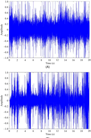
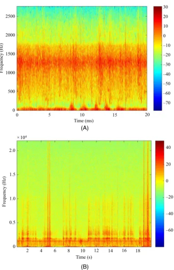
The hydrophone was used to record UWAN, and the sam-ples were converted into discrete time to enable more storage of processing in a personal computer. The measurements were based on various depths. Table 1 presents the factor specifi-cations for data collection in this study. The time representa-tion waveform for UWAN data gathered from two depths (8 m and 12 m) is presented in Figure 2. Figure 3 displays the time and frequency representation of the data. It describes both the time and frequency of the noise signal.
The data distribution was analyzed using the Gaussian and t-distributions by applying the fitting tool in MATLAB. By comparing the two distribution methods, Figure 4 shows that the PDF of UWAN adhered to the t-distribution, whereas the Gaussian distribution appeared inapt for UWAN.
Table 2 presents the degree of freedom for various depths for a short duration out of the total time. The state of UWAN was assumed stationary [17], and the average degree of
freedom was approximately 3. As UWAN was impulsive, the period of analysis was altered for the varied depths.
The PDF of t-distribution is expressed by the following equation [25]:
where Γ(·) refers to the gamma function, and nu denotes the de-gree of freedom that controls the distribution. A low nu results in wider PDF tails, whereas a high nu decreases the tails and converts it to Gaussian distribution. ρ(l, nu) refers to the prob-ability of observing a particular value of l from t-distribution with nu. The PDF in (1) displays zero mean and its variance is nu/(nu − 2), where nu ≥ 2. This signifies that the UWAN dismissed AWGN but adhered to t-distribution. To model a ran-dom variable X with variance σ > 2, the following changes in variables should be made:
(1) 𝜌(l,nu)= Γ � (nu + 1) ∕2� √ 𝜋nuΓ (nu∕2) � 1+ l 2 nu �−(nu+1) 2 (2) l= √ nu 𝜎2(nu − 2)x.
FIGURE 1 Experiment testing site
TABLE 1 Factor specifications for data collection
No. Factors Values
1. Location (1°49′21.8″N 102°50′14.3″E) 2. Frequency range 7 kHz–22 KHz
3. Surface temperature 29°C 4. Speed of wind 7 knots
5. Salinity 35 ppt
6. Depth 1 m–12 m
7. Sample of length 20 s
8. pH 7.8
FIGURE 2 Time representation of UWAN at two depths: (A)
8 m and (B) 12 m 1.0 0.8 0.6 0.4 0.2 0 –0.2 0 2 4 6 8 10 12 ed util p m A Time (s) –0.4 –0.6 –0.8 –1.0 14 16 18 20 1.0 0.8 0.6 0.4 0.2 0 –0.2 0 2 4 6 8 10 12 ed util p m A Time (s) –0.4 –0.6 –0.8 –1.0 14 16 18 20 (B) (A)
Accordingly, a new scaled PDF function can be written as,
For nu = 3, the PDF is,
The error performance is derived using the binary phase-shift keying (BPSK) signal. Finally, the symbol error proba-bility of the binary UWAN channel can be expressed as [18]:
The quadrature phase-shift keying (QPSK) constellation has dual BPSK signals at the quadrature stage. As noise does not rely statistically on quadrature elements, the following de-picts the two-bit symbol for correct decision probability [16]:
where P2 indicates the symbol error probability for BPSK modu-lation order. As P2 = PBPSK, the QPSK symbol error probability is as follows:
When nu = three, (5) is substituted in (7) so that the QPSK symbol error probability is given as,
3
|
COMMUNICATION SYSTEM
DESIGN
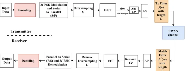
A UWA multicarrier F-OFDM communication system struc-ture is proposed in this paper, in which the signal processing embeds a transmitter and receiver. Figure 5 illustrates the un-derwater acoustic system (UWAS) based on F-OFDM, where the input data sequence X was encoded initially to generate the encoded data sequence X′. Various phase-shift keying (PSK) modulation families were used to map X′. Next, the baseband data were oversampled by inserting zeroes between the samples. The inverse fast Fourier transform (IFFT) was used to convert the data sequence to the time domain from the frequency domain.
The cyclic prefix (CP) operation expanded the OFDM sig-nal in time domain, in which the CP had a 7% value from the (3) fT(x, nu) = Γ � (nu+1) 2 � 𝜎√𝜋(nu − 2)Γ�nu 2 � � 1+ x 2 𝜎2(nu − 2) �−(nu+1) 2 . (4) fT(x, 3) =0.636 𝜎 ( 1+x2 𝜎2 )−2 . (5) PBPSK= 0.636 √ 2Eb No ∞ ∫ 0 [ 1+2Eb No (x + 1) 2 ]−2 dx. (6) Pc=(1− P2)2, (7) PQPSK= 1 − Pc= 2PBPSK{1− 0.5PBPSK}. (8) PQPSK= 1.272 � 2Eb No ∞ ∫ 0 � 1+2Eb No (x + 1) 2 �−2 dx ⎛ ⎜ ⎜ ⎝ 1− 0.318 � 2Eb No ∞ ∫ 0 � 1+2Eb No (x + 1) 2 �−2 dx ⎞ ⎟ ⎟ ⎠ . (9) x(n)=√1 N N�− 1 k= 0 X�kej2𝜋kn∕N, 0≤ n ≤ N−1.
FIGURE 3 UWAN time and frequency representation at two
depths: (A) 8 m and (B) 12 m
0 5 10 15 20 Time (ms) 2500 2000 1500 1000 )z H( yc ne uq er F 500 0 30 20 10 0 –10 –20 –30 –40 –50 –60 –70 2 6 10 14 18 Time (s) 2.0 1.5 1.0 0.5 )z H( yc ne uq er F × 104 0 40 20 0 –20 –40 –60 4 8 12 16 (A) (B)
TABLE 2 Degree of freedom for the various depths
Depth (m) Period (s) Degree of freedom (μm)
1 2.3 2.92
4 1.2 2.71
8 1.4 3.32
total data [26,27]. Finally, the OFDM signal x(n) was moved to a transmitter filter f(n) to generate an F-OFDM transmit-ting signal g(n).
The signal obtained at the receiver end was passed to a matching filter [28]. The serial data were converted into parallel, and the CP was discarded. Subsequently, fast Fourier transform (FFT) was employed to convert the data sequence to the frequency domain from the time domain. Oversampling was removed, a parallel signal was converted into serial, and various PSK demodulations were applied. Finally, decoding was performed to recover the encoded input data stream.
4
|
FILTER-OFDM FOR UWA
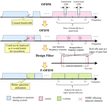
F-OFDM has been recommended as a candidate waveform framework for 5G wireless communication. The aim of F-OFDM is to minimize interruptions between adjacent sub-bands. Hence, to mitigate the out-of-band emission (OOBE), the OFDM baseband signal is usually filtered using a band-limited filter in every subband. This constricts the interruption from adjacent subbands to an extent. The suppression of OOBE, asynchronous transmission, and low latency are the typical fea-tures of filter-based waveform frameworks. Reducing the guard band between the symbols to increase the band in OFDM is essential to improve the data rate by minimizing the OOBE as illustrated in Figure 6. Thus, F-OFDM was applied to UWAS to improve the spectral efficiency and to increase the data rate.
(10) g(n)= x(n) ∗ f(n).
FIGURE 4 Comparison of UWAN distribution with Gaussian
and t-distributions at (A) 8 m and (B) 12 m (A) (B) 7 6 5 4 3 Densit y 2 1 0 –1.0 –0.8 Data –0.6 –0.4 –0.2 0 0.2 0.4 0.6 0.8 1.0 Data data Gaussian distribution t-distribution 4.5 4.0 3.5 3.0 2.5 yti sn e D2.0 1.5 1.0 –1.0 –0.8 Data –0.6 –0.4 –0.2 0 0.2 0.4 0.6 0.8 1.0 Data data Gaussian distribution t-distribution 0.5 0 (A) (B)
The design of the filter is integral for F-OFDM to achieve both frequency localization and more flexibility for time-fre-quency localization, mainly because the desired frequen-cy-domain localization leads to dispersion in the time domain [29]. The signal in an OFDM system has a rectangular pulse shape (sinc function), which leads to large side lobes on both sides of the signal in the frequency domain. Consequently, the frequency spectrum is not well localized. The sinc impulse response filter in F-OFDM, that is, a low-pass filter (LPF), is a suitable spectrum-shaping filter for the system due to its ability to suppress OOBE, in addition to not distorting the sig-nal passband. A time windowing mask offers excellent time localization, in addition to assuring a smooth transition at both filter impulse response ends [30]. The FIR filter is designed by multiplying the infinite impulse response of the LPF with a finite time-domain window [31]. The sinc impulse response filter of the time domain is as follows:
where hLPF(n) is the sinc impulse response of the LPF, wc refers to the cut-off frequency of the LPF, and w(n) denotes the impulse response of the windowing mask. Adopting a suitable window function offers a trade-off that is flexible for time-frequency lo-calization, which also limits the intersymbol interference (ISI) to a permissible level. As for F-OFDM, the rooted raised cosine (RRC) is more adequate, as it is more flexible than other existing window functions (eg, Remez and Hanning) [32]. The following expresses the time response of the RRC window [31]:
where L symbolizes the length of the filter, which is equal to half of the OFDM symbol length + 1, and α indicates the factor of roll-off, which limits the shape of the window to 0 ≤ α ≤ 1. Figure 7 shows that α = 1 denotes a hamming window, whereas
α = 0 signifies a rectangular window. F-OFDM allows its filter
length to exceed that of the CP to gain a balance for time-fre-quency localization and to attain better flexibility for the design of the filter [33]. However, more balance is acquired for time-fre-quency localization with the factor of roll-off in the RRC win-dow. Consequently, the RRC window is more suitable for the F-OFDM system than the other windows.
5
|
CHANNEL CODING
To gain an efficient acoustic system with a highly improved communication link, the channel coding was applied to any remaining error in the system. The main objective is to in-crease the BER reduction rate to an optimum level. In this study, two channel coding techniques were applied, namely turbo code and polar code.
5.1
|
Turbo code
Turbo codes are generally made of two parallel convo-lution encoders segregated by an interleaver [34]. The aim is to select the most appropriate interleaver and to construct polynomial codes for each encoder. As each encoder is deemed convolutional, the interleaver is as-sessed as a new component at the encoding stage. A turbo encoder using an interleaver is presented in Figure 8. The (11) f(n)= hLPF(n) ⋅ w(n), (12) hLPF(n)=sin(wc⋅ n) wc⋅ n , (13) wRRC(n)=[0.5 ( 1+ cos(2𝜋n L− 1 ))]𝛼 .
FIGURE 6 Differences between OFDM and F-OFDM
FIGURE 7 Window of passband with various roll-off factors 1.0 0.9 0.8 0.7 0.6 Am p 0.5 0.4 0.3 0.2 0.1 0 –150 n –100 –50 0 50 100 150 alfa = 0 alfa = 0.1 alfa = 0.2 alfa = 0.3 alfa = 0.4 alfa = 0.5 alfa = 0.6 alfa = 0.7 alfa = 0.8 alfa = 0.9 alfa = 1.0
initial encoder contains a systematic stream output, ut, and a parity stream, b1, whereas the second individual en-coder has an interleaving of the systematic stream and a second parity stream, b2, thus resulting in 1/2 turbo code. Furthermore, trellis termination is necessary at the de-coder to accept the first and last ende-coder states, mainly to hinder performance deterioration.
At the decoding part, two soft-input-soft-output (SISO) decoders represent the turbo decoder. The struc-tures of convolutional and turbo decoders are nearly the same, except for some minor changes. The decoding iter-ative scheme consists of an essential a posteriori proba-bility (APP) decoder, interleaver, and de-interleaver [35]. After encoding, the entire n-bit turbo code word could be assembled into the frame, modulated, transmitted over the channel, and then decoded. Let Ui denote the mod-ulating code bit (which could be either a systematic or parity bit), and Yi denote the corresponding received sig-nal. Note that Ui can only be 0 or 1, and Yi is a soft value. Therefore, the input of turbo decoder can be obtained by the following form [34]:
where P(Yi|Ui = j) is the conditional probability of the re-ceiving signal Yi given that the code bit Ui = j was trans-mitted. The probabilistic expression shown in (14) is called a log-likelihood ratio (LLR), and it is used throughout the decoding process. The calculation of the LLR equation re-quires not only a received signal sample Yi, but also some statistical knowledge from the channel based on the exper-imental measurements. For instance, if BPSK modulation is employed over a t-distribution channel in (4), then the corresponding decoder input in LLR form can be expressed as follows:
5.2
|
Polar code
The channel polarization transformer is used to build polar codes [36]. Here, it is assumed that the channels or the posi-tion of bits would undergo polarizaposi-tion, mainly because some channels are highly reliable, whereas some are not reliable for combining and splitting at infinite length. The channel capacity can be reached only if data bits are placed in reliable channels.
The task of polar code construction is to find the set of the most unreliable channels, which is usually called the frozen set. Several construction algorithms with a range of intricacies require the design-SNR component, mainly because the nature of polar codes is not universal, despite some possessing universal struc-tures. The polarization by the kernel reflects the encoder [36].
A larger input size can be acquired with this Kronecker product, as it allows the possession of dual power lengths in the polar codes. The descriptive code N refers to n = log2(N), whereas the following expresses the encoding:
where F⊗n denotes the F Kronecker product at n times. As il-lustrated in Figure 9A for code length = 4, the encoding is as given in (17). (14) R(ci)= log (p (yi|ci= 1) p(yi|ci= 0) ) , (15) R(Ui)= log ( 𝜎+ (Yi− 1) 𝜎+ (Yi+ 1) ) . (16) F= ⎡ ⎢ ⎢ ⎣ 1 0 1 1 ⎤ ⎥ ⎥ ⎦ . (17) G= F⊗n
FIGURE 8 Turbo code structure [35]
FIGURE 9 Polar code with a length of 4: (A) encoder and (B)
decoder [36]
u
1u
2u
3u
4c
1c
2c
3c
4 ⊕ (A) (B)Although belief propagation can be used to decode polar codes, successive cancelation (SC) is the standard decoding algorithm. This SC decoder may be obtained from the en-coder directly along the probabilistic nodes. Both XOR and connection nodes are represented as follows. Calculations for LLRs a and b [35] performed by f and g nodes within the LLR domain are expressed as follows:
where s reflects the partial sum. This sum is obtained from past decoded bits to be incorporated into the present g node. The yield gained after applying f into an approximation is expressed as follows:
Figure 9B propagates the LLRs from right to left. This is denoted as Lsi in the figure. Upon passing LLRs using correct f nodes, the initial bit, u1, may be directly decoded, whereas the
g node is used to decode u2, which requires the partial sum. With the sole involvement of u1, the partial sum becomes equivalent to u1. The decoder sets the value to zero if u1 is in a frozen state. Next, u1 and LLRs are used for the decoding of u2, thus resulting in a lower u2 decoding performance. The decoding process halts after accessing all the nodes.
6
|
RESULTS AND DISCUSSION
This section presents the results of the UWAS simulations to evaluate the performance of channel coding based on OFDM and F-OFDM. Table 3 shows the simulation parameters
(18) c= uG. (19) f(a, b)= log ( ea+b+ 1 ea+ eb ) g(a, b, s)= ( − 1)sa+ b , (20) f(a, b)= sign(a)sign(b)min(|a|, |b|).
FIGURE 10 Comparison of F-OFDM and OFDM BER at nu = 3: (A) BPSK, (B) QPSK, and (C) 16PSK
10–1 –5 0 5 Bi te tar ror re Eb/No(dB) 10–2 10–3 10–4 10 15 Turbo OFDM Polar OFDM Turbo F-OFDM Polar F-OFDM Uncoding OFDM Uncoding FFDM 100 10–1 –5 0 5 Bi t eta r r orr e Eb/No(dB) 10–2 10–3 10–4 10 15 Turbo OFDM Polar OFDM Turbo F-OFDM Polar F-OFDM Uncoding OFDM Uncoding FFDM 100 10–1 –5 0 5 Bi te tar ror re Eb/No(dB) 10–2 10–3 10–4 10 15 Turbo OFDM Polar OFDM Turbo F-OFDM Polar F-OFDM Uncoding OFDM Uncoding FFDM 100 (A) (B) (C)
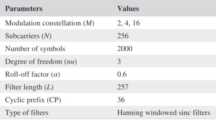
TABLE 3 Simulation parameters for the baseline
Parameters Values
Modulation constellation (M) 2, 4, 16
Subcarriers (N) 256
Number of symbols 2000 Degree of freedom (nu) 3 Roll-off factor (α) 0.6 Filter length (L) 257 Cyclic prefix (CP) 36
applied for the communication scheme. The UWAS was evaluated in two phases. First, the BER performance of both turbo and polar codes was assessed and compared in terms of SNR. Second, both F-OFDM and OFDM were analyzed and their performances were compared in terms of power spectral density (PSD). The results of the simulations were obtained from the fitting tool of MATLAB in the presence of additive
t-distribution noise with a nu value of 3.
6.1
|
BER performance
The simulation results of BER with Eb/No are shown in Figure 10. The turbo code data of OFDM and F-OFDM are presented in pink and red, respectively. The polar code data of OFDM and F-OFDM are presented in black and blue, re-spectively. The uncoded data for OFDM and F-OFDM are pre-sented in yellow and green, respectively. The Max-Log-MAP and SC decoding algorithms were employed for the turbo and polar codes, respectively. Note that both algorithms have used an R rate of 1/2. Figure 10A illustrates that the performance yielded by the turbo code is better than that of the polar code in F-OFDM and OFDM by 2 dB at BER 10−3. The performance variance between uncoded OFDM and F-OFDM was nearly nonexistent, whereas a substantial variance in performance was observed between uncoded turbo and polar codes, that is, ap-proximately 8 and 6 dB, respectively. According to the results shown in Figure 10, the performance of BER depends on the modulation family used and the words of constellation map-ping. A high order of constellation reduces the performance of BER, as the latter is highly sensitive to the interference.
In contrast, comparing Figure 10A with Figure 11A, it can be observed that the BER is improved to 1.5 × 10⁻⁴ at 7 dB approximately, and 1.02 × 10⁻⁴ at 5 dB for turbo and polar coding, respectively, when nu is increased. Therefore, the t-distribution converges to Gaussian distribution as nu increases. This improvement in BER is similarly observed when QPSK and 16 QPSK are considered.
The use of polar and turbo codes has both advantages and disadvantages related to the information performance, error correction performance, and computational complexity. The computational complexity of a polar decoder is lower than that of a turbo decoder. However, in terms of informa-tion performance, the polar code uses low coding rates and long block lengths. For practical applications, such features should be considered when choosing the channel code.
6.2
|
Computational complexity
The parameters related to the computational complexity used
for the turbo code are the information block length (K), the FIGURE 11 Comparison of F-OFDM and OFDM BER at nu = 4: (A) BPSK, (B) QPSK, and (C) 16PSK 10–1 –5 0 5 Bi te tar ror re Eb/No(dB) 10–2 10–3 10–4 10 15 Turbo OFDM Polar OFDM Turbo F-OFDM Polar F-OFDM Uncoding OFDM Uncoding FFDM 100 10–1 –5 0 5 Bi te tar ror re Eb/No(dB) 10–2 10–3 10–4 10 15 Turbo OFDM Polar OFDM Turbo F-OFDM Polar F-OFDM Uncoding OFDM Uncoding FFDM 100 10–1 –5 0 5 Bit eta rr orr e Eb/No(dB) 10–2 10–3 10–4 10 15 Turbo OFDM Polar OFDM Turbo F-OFDM Polar F-OFDM Uncoding OFDM Uncoding FFDM 100 (A) (B) (C)
memory length of the component (m), and the number of it-erations (Imax) according to [37]. The encoded block length (N) is related to the polar code [36]. Equations (21) and (22) show the computational complexities of turbo and polar codes, respectively.
where K is a set varying as 32 ≤ k ≤ 1024 bits, N = k/R,
R = 1/2 m = 10, and Imax = 8. The efficiency of the polar code technique was evaluated in terms of its ability in re-ducing the computational complexity. Figure 12 shows the variation of the computational complexity with respect to the K value. By comparing both techniques, it can be ob-served that the lowest computational complexity was re-ported for the polar code.
6.3
|
Performance PSD
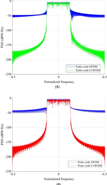
In this section, the performances of F-OFDM and OFDM schemes are evaluated based on the PSD. Figure 13 presents the differences in the PSDs resulting from the signals of F-OFDM and OFDM. The OOBE for turbo and polar codes based on OFDM was −45 dBW/Hz. However, the OOBE was −80.02 dBW/Hz for the turbo code and −85.56 dBW/Hz for the polar code after using the F-OFDM scheme. Therefore, F-OFDM provides better frequency localization compared with OFDM.
Figure 14 shows the baseband impulse response of the built filter. It can be observed that the main energy of the
filters is limited to the main lobe of sin. Therefore, the energy of the filter remains confined to the length of the CP. The BER values shown in Figure 10 indicate the limited ISI. (21)
CT= Imax× 16 × K × 2m+ Imax× 8 × K × 2m,
(22) CP= N ⋅ log2(N),
FIGURE 14 Impulse response of the designed filter for F-OFDM
0.25 0.20 0.15 0.10 0.05 0 –0.05 0 5 10 15 20 25 30 Amplitude Time (ms)
FIGURE 13 Comparison of F-OFDM and OFDM PSD: (A)
turbo code and (B) polar code
0 –250 0 PSD (dBW/Hz) Normalized frequency –200 –150 –100 –50 –0.5 –0.5
Turbo code OFDM Turbo code F-OFDM
0 –250 0 PSD (dBW/Hz) Normalized frequency –200 –150 –100 –50 –0.5 –0.5
Polar code OFDM Polar code F-OFDM
(A)
(B)
FIGURE 12 Computational complexity of the turbo and polar
decoders 109 108 107 106 105 yti xel p mo c l an oit atu p mo C 104 103 102 32 64 128 256
Information block length (K)512
1024 Polar
7
|
CONCLUSION
This paper presented a new waveform F-OFDM system based on the UWA communication channel. The new system successfully suppressed the guard band, and its ISI was de-creased by using a filter. Upon comparing the performances of polar and turbo codes, this study proposes polar coding based on the UWA channel coding scheme. The results ob-tained from MATLAB simulations highlighted the feasi-bility offered by polar coding based on the UWA channel coding scheme. This coding scheme also enhanced the rate of corrected data, in addition to minimizing the BER in the communication system effectively. As for the turbo code, its error rate was lower than that of the polar code. However, the drawbacks of the turbo code are a massive algorithm com-plexity for decoding, a demand for an interleaver, and time delay. This indicates the higher efficiency of polar codes for underwater communication system compared with that of turbo codes. Regarding complexity and time delay, the turbo code appeared to be competitive in correcting error codes. Moreover, when the SNR exceeded 8 dB, the error rate in the system was 10−3 for BPSK and QPSK. Thus, reliable underwater communication can be achieved when the SNR exceeds 8 dB.
ORCID
Mustafa Sami Ahmed https://orcid. org/0000-0002-3741-7091
Mohammed S. M. Gismalla https://orcid. org/0000-0001-8743-6859
Yasir Amer Jawhar https://orcid. org/0000-0002-6506-5433
REFERENCES
1. P. Chen et al., Joint channel estimation and impulsive noise
mitiga-tion in underwater acoustic OFDM communicamitiga-tion systems, IEEE
Trans. Wirel. Commun. 16 (2017), 6165– 6178.
2. M. Chitre, S. Ong, and J. Potter, Performance of coded OFDM in
very shallow water channels and snapping shrimp noise, in Proc.
OCEANS MTS/IEEE (Washington, DC, USA), Sept. 2005, pp. 996– 1001.
3. R. Gomathi and J. M. L. Manickam, PAPR reduction technique
using combined DCT and LDPC based OFDM system for un-derwater acoustic communication, ARPN J. Eng. Appl. Sci. 11
(2016), 4424– 4430.
4. M. Chitre, J. Potter, and O. S. Heng, Underwater acoustic
chan-nel characterisation for medium- range shallow water communi-cations, in Proc. OCEANS’04. MTTS/IEEE TECHNO- OCEAN
(Kobe, Japan), Nov. 2004, pp. 40– 45.
5. L. Liu et al., Design and implementation of channel coding for
underwater acoustic system, in proc. IEEE Int. Conf. on ASIC
(Changsha, China), Oct. 2009, pp. 497– 500.
6. M. S. Ahmed et al., Filtered- OFDM with channel coding based
on T- distribution noise for underwater acoustic communication, J.
Ambient Intell. Humaniz. Comput. 11 (2020), 1– 14.
7. C. Seo et al., Performance comparison of convolution and Reed-
Solomon codes in underwater multipath fading channel, Jpn. J.
Appl. Phys. 53 (2014), 07KG02:1– 4.
8. J. Trubuil, A. Goalic, and N. Beuzelin, Synchronization and
chan-nel coding in shallow water acoustic communication, in Proc.
OCEANS (Quebec, Canada), Sept. 2008, pp. 1– 5.
9. J. Huang, S. Zhou, and P. Willett, Nonbinary LDPC coding for
multicarrier underwater acoustic communication, IEEE J. Sel.
Area. Comm. 26 (2008), 1684– 1696.
10. B. Vasić, P. Ivaniš, and S. Brkic, Low complexity memory
architec-tures based on LDPC codes: Benefits and disadvantages, in Proc.
Telecommun. Modern Satellite, Cable Broadcasting Services (Nis, Serbia), Oct. 2015, pp. 11– 18.
11. L. Liu et al., Channel coding for underwater acoustic
single- carrier CDMA communication system, in Proc. Int.
Conf. Electron. Inf. Eng. (Nanjing, China), Jan. 2017, pp. 103222S:1– 10.
12. W. Han, J. Huang, and M. Jiang, Performance analysis of
under-water digital speech communication system based on LDPC codes,
in Proc. IEEE Conf. Ind. Electron. Applicat. (Xian, China), May 2009, pp. 567– 570.
13. Y. A. Jawhar et al., A review of partial transmit sequence for
PAPR reduction in the OFDM systems, IEEE Access 7 (2019),
18021– 18041.
14. Y. A. Jawhar et al., New low- complexity segmentation scheme
for the partial transmit sequence technique for reducing the high PAPR value in OFDM systems, ETRI J. 40 (2018), 699– 713.
15. J. Panaro et al., Underwater acoustic noise model for shallow water
communications, in Proc. Brazilian Telecommun. Symp. 2012.
16. S. Banerjee and M. Agrawal, On the performance of underwater
communication system in noise with Gaussian mixture statistics, in
Proc. National Conf. Commun. (Kanpur, India), 2014, pp. 1– 6. 17. M. Stojanovic and J. Preisig, Underwater acoustic communication
channels: Propagation models and statistical characterization,
IEEE Commun. Mag. 47 (2009), 84– 89.
18. N. S. M. Shah, Y. Y. Al- Aboosi, and M. S. Ahmed, Error
perfor-mance analysis in underwater acoustic noise with non- Gaussian distribution, Telkomnika 16 (2018), 681– 689.
19. Y. Y. Al- Aboosi and A. Z. Sha’ameri, Improved underwater signal
detection using efficient time– frequency de- noising technique and Pre- whitening filter, Appl. Acoust. 123 (2017), 93– 106.
20. J. Panaro et al., Underwater acoustic noise model for shallow water
communications, in Brazilian Telecomm. Symp., 2012.
21. D. Li, Y. Wu, and M. Zhu, Nonbinary LDPC code for noncoherent
underwater acoustic communication under non- Gaussian noise, in
Proc. IEEE Int. Conf. Signal Process. Commun. Comput. (Xiamen, China), Oct. 2017, pp. 1– 6.
22. A. Goalic, J. Trubuil, and N. Beuzelin, Channel coding for
under-water acoustic communication system, in Proc. OCEANS (Boston,
MA, USA), Sept. 2006, pp. 1– 4.
23. Y. Y. Al- Aboosi et al., Diurnal variability of underwater acoustic
noise characteristics in shallow water, Telkomnika 15 (2017), 314.
24. Y. Y. Al- Aboosi and A. Z. Sha‘ameri, Improved signal de- noising
in underwater acoustic noise using S- transform: A performance evaluation and comparison with the wavelet transform, J. Ocean
Eng. Sci. 2 (2017), 172– 185.
25. M. Ahsanullah, B. G. Kibria, and M. Shakil, Normal and student’s T distributions and their applications, Springer, Paris, Netherlands, 2014.
26. Y. A. Al- Jawhar et al., Zero- padding techniques in OFDM systems, Int. J. Electr. Eng. Inform. 10 (2018), 704– 725.
27. A. Hammoodi, L. Audah, and M. A. Taher, Green coexistence
for 5G waveform candidates: A review, IEEE Access 7 (2019),
10103– 10126.
28. D. Wu et al., A field trial of f- OFDM toward 5G, in Proc. IEEE Globecom Workshops (Washington, DC, USA), Dec. 2016, pp. 1– 6.
29. R. Gerzaguet et al., The 5G candidate waveform race: A
compari-son of complexity and performance, EURASIP J. Wirel. Commun.
Netw. 13 (2017), 1– 14.
30. J. Wang et al., Spectral efficiency improvement with 5G
technol-ogies: Results from field tests, IEEE J. Sel. Area. Commun. 35
(2017), 1867– 1875.
31. D. Wu et al., A field trial of f- OFDM toward 5G, in Proc. Globecom Workshops (Washington, DC, USA), Dec. 2016, pp. 1– 6. 32. Y. Jawhar et al., New low complexity segmentation scheme of
par-tial transmit sequence technique to reduce the high PAPR value in OFDM systems, ETRI J. 40 (2018), 1– 15.
33. F. Schaich and T. Wild, Waveform contenders for 5G— OFDM
vs. FBMC vs. UFMC, in Proc. Commun., Contr. Signal Process.
(Athens, Greece), May 2014, pp. 457– 460.
34. C. Berrou, A. Glavieux, and P. Thitimajshima, Near Shannon limit
error- correcting coding and decoding: Turbo- codes. 1, in Proc.
ICC 93- IEEE Int. Conf. Commun. (Geneva, Switzerland), May 1993, pp. 1064– 1070.
35. B. Tahir, S. Schwarz, and M. Rupp, BER comparison between
convolutional, turbo, LDPC, and polar codes, in Proc. Int. Conf.
Telecommun. (Limassol, Cyprus), May 2017, pp. 1– 7.
36. E. Arikan, Channel polarization: A method for constructing
capacity- achieving codes for symmetric binary- input memoryless channels, IEEE Trans. Inf. Theory 55 (2009), 3051– 3073.
37. Z. R. M. Hajiyat et al., Channel coding scheme for 5G mobile
com-munication system for short length message transmission, Wirel.
Pers. Commun. 106 (2019), 377– 400.
AUTHOR BIOGRAPHIES
Mustafa Sami Ahmed received his
BS degree in computer communica-tion engineering from the AL Rafidain University College, Baghdad, Iraq, in 2011, and his MS degree in engineer-ing from the Faculty of Electrical and Electronic Engineering, University Tun Hussein Onn Malaysia, Johor, Malaysia, in 2015. He is currently working toward his PhD degree in communi-cation engineering from the University Tun Hussein Onn Malaysia. His research interests are underwater acoustic communication, digital signal processing, and wireless communication.
Nor Shahida Mohd Shah received
her BEng degree in electrical engi-neering from Tokyo Institute of Technology, Tokyo, Japan, in 2000, her MSc degree from the University of Malaya, Kuala Lumpur, Malaysia, in 2003, and her PhD degree from Osaka University, Osaka, Japan, in 2012. Since 2004, she has been with the Faculty of Electrical and Electronic Engineering, University Tun Hussein Onn Malaysia, Johor, Malaysia, where she is now a senior lecturer. Her main research interests are optical fiber devices, optical communication, nonlinear optic, optical signal process-ing, antenna and propagation, and wireless communication.
Yasin Yousif Al-Aboosi received his
BE degree in electronics and commu-nication engineering from Baghdad University, Iraq, in 1995, and his ME degree in communication engineering from Technology University, Iraq, in 2003. He received his PhD degree from UTM, Malaysia, in 2017. He is currently an assistant professor at the Department of Electrical Engineering, College of Engineering, Mustansiriyah University, Iraq. His main research interests are underwater acoustic com-munication, signal processing, and medical image processing.
Mohammed S. M. Gismalla, received
his BSc (Hons) degree in electronic and electrical engineering (Communication) from the International University of Africa (IUA), Sudan, in 2010, and his MSc degree in electronic engineering (com-munication) from Sudan University of Science and Technology in 2015. He worked as a teaching assistant at the Department of Communication Engineering, Faculty of Electronic and Electrical Engineering at IUA in 2010 and was promoted to lecturer in 2015. He is working to-ward his PhD degree at the University Tun Hussein Onn Malaysia (UTHM), Malaysia. His research interests are visible light communication, Internet of things, and D2D communication. He is a student member of IEEE.
Mohammad F. L. Abdullah received
his BSc (Hons) degree in electrical en-gineering (communication) in 1997, Dip Education in 1999, and his MEng degree by research in optical fiber communication in 2000 from the University of Technology Malaysia (UTM). He completed his PhD degree in wireless optical communication engineering in August 2007 from the University of Warwick, the United Kingdom. He worked as a lecturer at Polytechnic Seberang Prai (PSP) in 1999 and was transferred to UTHM in 2000 (formerly known as PLSP). Currently, he is a professor at the Department of Electronics Engineering, Faculty of Electrical & Electronic Engineering, and Senate Member University Tun Hussein Onn Malaysia (UTHM). He had 20 years of experience in teaching higher education, which involved subjects such as optical fiber communication, advanced optical commu-nication, and advanced digital signal processing. His re-search areas of interest are wireless and optical communi-cation, material solar cell fabricommuni-cation, image watermarking technique, and railway engineering in communication. He is a senior member of IEEE, a charter engineer (CEng), and a senior member of IET.
Yasir Amer Jawhar received his BS
degree in electrical engineering from the College of Engineering, University of AL-Mustansiriyah, Baghdad, Iraq, in 1998, and his MS degree in engi-neering from the Faculty of Electrical and Electronic Engineering, University Tun Hussein Onn Malaysia, Johor, Malaysia, in 2015. He received his PhD in communication engineering from the University Tun Hussein Onn Malaysia in 2019. His main research interests are signal processing in communication, OFDM, PAPR reduction in Multicarrier system, 5G wave-form design, and wireless network.
Mohammed Balfaqih received his
MS degree in communication engi-neering from International Islamic University Malaysia, Selangor, Kuala Lumpur, Malaysia, and his PhD de-gree in electrical, electronics, and sys-tems engineering from Universiti Kebangsaan Malaysia, Selangor, Bangi, Malaysia. He is currently an assistant professor with the Department of Computer Network and Engineering, University of Jeddah, Jeddah, Makkah Al-Mukarramah, Saudi Arabia, and also a senior researcher with Automobile Transportation Department, South Ural State University, Chelyabinsk Oblast, Chelyabinsk, Russia. His principal research inter-ests are wireless communication, mobility management, IoT, network virtualization, and artificial intelligence.
![FIGURE 8 Turbo code structure [35]](https://thumb-ap.123doks.com/thumbv2/123dokinfo/4873171.33227/7.892.464.822.57.450/figure-turbo-code-structure.webp)