DTM GENERATION OF RADARSAT AND SPOT SATELLITE IMAGERY USING GROUND CONTROL POINTS
EXTRACTED FROM SAR IMAGE
DOO-YOUL PARK*, JIN-KWANG KIM*, HO-NAM LEE* and JOONG-SUN WON**
*Chung-Ang Aerosurvey Co. Imagery and Information Business Dept.
18 Kyonam-dong, Chongro-gu, Seoul 110-100, Korea [email protected]
**Department of Earth System Sciences, Yonsei University, 134 Sinchon-dong, Seodaemun-gu, Seoul 120-749, Korea
ABSTRACT:
Ground control points(GCPs) can be extracted from SAR data given precise orbit for DTM generation using optic images and other SAR data. In this study, we extract GCPs from ERS SAR data and SRTM DEM. Although it is very difficult to identify GCPs in ERS SAR image, the geometry of optic image and other SAR data are able to be corrected and more precise DTM can be constructed from stereo optic images. Twenty GCPs were obtained from the ERS SAR data with precise Delft orbit information. After the correction was applied, the mean values of planimetric distance errors of the GCPs were 3.7m, 12.1 and -0.8m with standard deviations of 19.9m, 18.1, and 7.8m in geocentric X, Y, and Z coordinates, respectively. The geometries of SPOT stereo pair were corrected by 13 GCPs, and r.m.s. errors were 4.5m, 7.5m and 8.6m in northing, easting and height direction, respectively. And the geometries of RADARSAT stereo pair were corrected by 12 GCPs, and r.m.s. errors were 8.4m, 7.9m and 6.9m in northing, easting and height direction, respectively. DTMs, through a method of area based matching with pyramid images, were generated by SPOT stereo images and RADARSAT stereo images. Comparison between points of the obtained DTMs and points estimated from a national 1:5,000 digital map was performed. For DTM by SPOT stereo images, the mean values of distance errors in northing, easting and height direction were respectively -7.6m, 9.6m and -3.1m with standard deviations of 9.1m, 12.0m and 9.1m. For DTM by RADARSAT stereo images, the mean values of distance errors in northing, easting and height direction were respectively -7.6m, 9.6m and -3.1m with standard deviations of 9.1m, 12.0m and 9.1m.These results met the accuracy of DTED level 2
KEY WORDS: DTM, GCP, ERS SAR, SPOT, RADARSAT
1. INTRODUCTION
The generation of digital terrain model (DTM) is an important work for many remote sensing applications such as ortho-rectification, terrain related radiometric correction, map revision and so on. Various remotely sensed images can be used to construct DTM using intersection of stereo data or interferometry of SAR pairs.
These methods require precise orbit information in order to correct the distortion of image’s geometry. If the accuracy of satellite’s orbit is poor, the geometries of images must be corrected using GCPs.
Because of precise orbit, InSAR technique generating DTM from ERS tandem pair without GCPs is prevalent (Zebker et al., 1994). It is, however, difficult to construct DTM using SAR data where layover and radar shadow are severe. In these areas, optic imagery such as SPOT images is preferable. Optic images need either GPS surveyed data or geographical map to generate DTM.
The geometry of image must be corrected using GCPs because the accuracy of SPOT satellite’s orbit is poor (Orun et al., 1994; Radhadevi et al., 1998; Jung et al.,
2004), but there are many regions where GCPs are not available. In order to resolve this problem, ERS SAR image with precise orbit and SRTM DEM are used to extract GCPs. Although GCP selection in steep mountainous relief on ERS SAR image is a difficult process, it is still possible to carry out using ridge points, the common feature, and so on (Thierry et al., 1998).
And then, the registration of ERS image and SPOT image can be achieved with several methods (Dare et al., 2001;
Raucoules et al., 1999). Using the registered GCPs, SPOT orientation modeling such as bundle adjustment and DTM generation (Chen et al., 1993) using SPOT stereo images are performed. Also, accuracy assessment of modeling and DTM are carried out.
In order to validate the availability of modeling and DTM construction using RADARSAT stereo image with same GCPs, same processing is applied to RADARSAT stereo images.
2. METHODOLOGY 2.1 Data
In this study, ERS SAR data, SRTM DEM, a SPOT stereo pair and a RADARSAT stereo pair were taken.
The test area of Daejon in Korea was selected. First, the amplitude image was computed from an ERS-1 SAR SLC data acquired on 22 December 1995. A SPOT stereo pair has incidence angles of -22.7 and 8.6 degrees in left and right image, respectively. A RADARSAT stereo pair was taken on 6 January 1997 and 10 January 1997 in path image plus (SGX) type by RADARSAT-1.
2.2 Geolocation for SAR
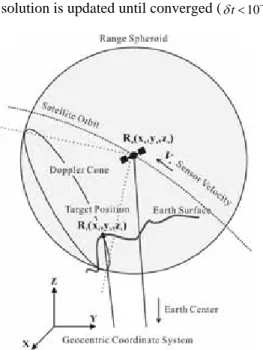
Fig. 1 presents the imaging geometry of SAR. The following two basic equations are expressed as the Doppler cone and range spheroid (Curlander et al., 1991;
Hong et al., 2004).
Doppler equation is
( ) ( )
02 − ⋅ − =
= s t s t
DC V V R R
f R
λ (1)
And, range equation is
t
s R
R
R= − (2)
where DC is the Doppler central frequency and to be zero after zero Doppler processing,
f λ
is radarwavelength,
R
is slant range distance, Rsand t are position vector of sensor and target, respectively, and Vs and t are velocity vector of sensor and target, respectively.R V
These two equations enable us to convert Cartesian coordinates (X, Y, Z) into image coordinates (line, pixel).
If the orbit of satellite is very precise such as Delft orbit, most errors must result from azimuth timing error. In order to correct the timing error, equation (1) is differentiated with respect to azimuth time. And then, azimuth time is updated by Newton-Rapson method spheroid (Curlander et al., 1991). Two equations to solve this method are given as
( ) ( )
{
( )( )
[ ]
2}
2
/ 2
R V V R R
V V A A R R R
dt df
t s t s
t s t s t s DC
−
−
−
− +
−
⋅
−
=λ (3)
dt f df t=− DC/ DC
δ (4)
The solution is updated until converged (δt<10−6 )
Fig.1. Radar imaging geometry
2.3 Geolocation for CCD camera
The various methods for the orientation modeling for CCD camera presented by Fig. 2 have been studied. One of them is bundle adjustment (Orun et al., 1994; Chen et al., 1993). The bundle adjustment method is a traditional method using the collinearity condition, which states that the exposure station, any object point, and its image point all lies along a straight line. The following two equations expressed as collinearity condition (Chen et al., 1993) are given as
) ( ) (
) (
) ( ) ( ) (
33 32
31
13 12
11
s t s
t s
t
s t s
t s
t
i m x x m y y m z z
z z m y y m x x f m
x − + − + −
− +
− +
− −
= (5)
) ( ) ( ) (
) ( ) ( ) (
33 32
31
23 22
21
s t s
t s
t
s t s
t s
t i
y m x x m y y m z z
z z m y y m x x f m y
S − + − + −
− +
− +
− −
=
(6)
Fig. 2. The imaging geometry of CCD camera
where i and i are image coordinate pixel and line for point i, respectively, m11, , …, and
m
33 are elements of the rotation matrix, is focal length, andis scale affinity.
x y
m12
f S
y2.4 GCP selection
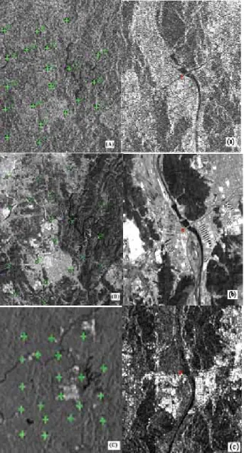
It was difficult to select GCPs on ERS, SPOT and RADARSAT images in mountainous area. However, the points such as ridge points, and common feature were defined GCPs. Fig. 3 displays the ERS, SPOT and RADARSAT images with GCPs in test area. 20 GCPs were selected for the orientation modeling of SPOT stereo pair and RADARSAT stereo pair.
It was hard to find identical points due to the difference of radiometric properties between SPOT, ERS and RADARSAT image, but not impossible to select those points. Fig. 3 shows a selected point in the clip images of ERS, SPOT and RADARSAT images.
Fig. 3. The selected GCPs and identical point in ERS (A), (a), SPOT (B), (b) and RADARSAT (C), (c).
2.5 GCP coordinates (X, Y, Z) calculation
Two basic equations (1) and (2) with corrected parameters can not convert image coordinates (line, pixel) to Cartesian coordinates (X, Y, Z), but possible to convert Cartesian coordinates (X, Y, Z) into image coordinates (line, pixel).
Three parameters of X, Y, and Z can not be calculated by two equations (1) and (2). One of three parameters needs to be known value to solve it. It is supposed that the value of Z is known, then values of X, Y are calculated. This task was carried out as follow.
• Calculation of total mean height,
Z
using SRTM DEM at test area.• Computation of (X, Y) using (line, pixel,
Z
)• Finding minimum and maximum height of and around (5000m X, 5000m
Zmin
Z
max± ±
Y).• Computation of (X, Y) using (line, pixel,
=
Z
min max• Calculation of
Z -50m to
Z
+50m)'
Z
at (X, Y) using SRTM DEM• Finding the position(s) at Z − Z'≈0
• selection of position having short slant range distance if more than two point is found
3. RESULT
Table I presents the mean, RMSE, min, and max of the errors between GCPs coordinates (X, Y, Z) calculated by two basic equations (1) and (2), and corresponding points coordinates in a national 1:5,000 scale digital map.
As shown in Table I, the RMSE, minimum and maximum values of X, Y and Z were high. The big errors must be caused by wrong identified points in ERS image and long gird spacing, 3 arc seconds, of SRTM DEM. All of them could not be applied directly to the modeling of SPOT and RADARSAT image, so these wrong points had to be removed out. The elimination of wrong points was carried out during orientation modeling.
TABLE I. Accuracy Statistics of GCPs calculated on ERS image
Errors Mean(m) RMSE(m) Min.(m) Max.(m)
X 11.2 46.4 -90.7 163.1
Y 20.2 62,6 -34.6 266.0
Z -9.7 26.4 -109.0 7.4
The bundle adjustment method (Orun et al., 1994;
Chen et al., 1993) with 20 GCPs is performed for SPOT and RADARSAT stereo pair. We suppose that RMSE of GCPs are random variables, and remove GCPs using 99% confidence interval. The mean, RMSE, min, and max of the errors of 13 GCPs for SPOT stereo pair are shown in Table II. .The same accuracy statistics of 12 GCPs for RADARSAT stereo pair are shown in Table III.
TABLE II. Accuracy statistics of the 13 GCPs except for 7 eliminated GCPs.
Errors Mean(m) RMSE(m) Min.(m) Max.(m)
X 3.7 19.9 -39.2 40.9
Y 12.1 18.1 -3.5 50.9 Z -0.8 7.8 -21.9 7.4
TABLE III. Accuracy statistics of the 12 GCPs except for 8 eliminated GCPs.
Errors Mean(m) RMSE(m) Min.(m) Max.(m)
X 7.5 23.3 -39.2 46.8
Y 15.7 20.1 -22.6 50.9
Z -3.1 9.3 -21.9 7.4
The RMSE of SPOT and RADARSAT modelling are shown in Table IV. There is not big difference between two RMSE, 12.1 for SPOT and 13.4 for RADARSAT.
TABLE IV. The RMSE of Modeling RMSE(m)
Image X Y Z Total
SPOT 4.0 7.5 8.6 12.1
RADARSAT 8.4 7.9 6.8 13.4
DTM was generated by using a SPOT stereo pair and RADARSAT stereo pair with GCPs obtained from ERS SAR data. LSM (Least Square Matching) method (Chen et al., 1993) using the pyramid images is applied to the pair.
Table V. presents the mean, RMSE, min., and max. of the errors between GCPs coordinates, (X, Y, Z) computed by the intersection of SPOT stereo pair and corresponding points coordinates in a national 1:5,000 scale digital map.
Table VI. presents same accuracy statistics for RADARSAT stereo pair.
The generated DTMs meet the accuracy of DTED level 2, which has 50 m and 30 m in absolute horizontal and vertical error, respectively.
TABLE IV. Accuracy statistics of GCPs calculated on the intersection of SPOT stereo pair.
Errors Mean(m) RMSE(m) Min.(m) Max.(m)
X 7.6 9.1 -11.5 27.5
Y 9.6 12.0 -8.3 42.2
Z -3.1 9.1 -21.2 21.5
TABLE VI. Accuracy statistics of GCPs calculated on the intersection of RADARSAT stereo pair.
Errors Mean(m) RMSE(m) Min.(m) Max.(m)
X 11.5 21.3 -26.6 19.1
Y 15.3 24.1 -28.7 32.8
Z -9.2 18.2 -32.0 11.9
4. CONCLUSION
The method to generate DTM using GCPs extracted from SAR image was studied. The geolocation using ERS SAR data with Delft precise orbit and SRTM DEM with the vertical accuracy of 16 m was carried out. The extracted GCPs from ERS image had the good accuracy except GCPs by man-made error and SRTM DEM error.
Bad GCPs were efficiently removed during orientation modeling of a SPOT and RADARSAT stereo pairs.
Finally, the DTMs were generated using LSM method, and the accuracies meet that of DTED level 2.
Where there are no GCPs and DTM cannot be generated using InSAR technique, the proposed method would be very available.
5. REFERENCES
Zebker, H.A.,. Werner, C.L., Rosen, P.A., and Hensley, S., “Accuracy of topographic maps derived from ERS-1 interferometric radar” IEEE Trans. Geosci. Remote Sens., vol. 32, p.823-836, 1994.
Orun, A. B. and K. Natarajan, “A modified bundle adjustment software for SPOT imagery and photography:
Tradeoff”, PE&RS, vol. 60, no. 12, pp. 1431-1437, 1994.
Radhadevi, P. V., R. Ramachandran and A. S. R. K. V.
Murali Mohan, “Restitution of IRS-1C PAN data using an orbit attitude model and minimum control”, ISPRS J.
Photogramm. Remote Sensing, vol. 53, pp. 262-271, 1998.
Jung, H. S., Kim, S. W. and Won, J. S., “The simple method of geometric reconstruction for SPOT images”, International Symposium of Remote Sensing ’04, Jeju, pp.
205-207, 2004.
Toutin, T., Hoja, D., Hoeppner, E., Remond, A., and King, C., “GCPs Selection from Multi-source Data Over Mountainous Topography”, In Proceedings of IGARSS ’98, CDROM, Seattle, 1998.
Dare, P., and Dowman, I., “An improved model for automatic feature-based registration of SAR and SPOT images”, ISPRS J. Photogramm. Remote Sensing, vol. 56, pp. 13-28, 2001.
Raucoules, D., and Carnec, C., “Use of interferometric phase for co-registration of ERS SAR and SPOT images”, CEOS Symp. 99’, Touluse, pp. 114-118, 1999.
Chen L. C. and Rau J. R., “A unified solution for digital terrain model and orthoimage generation from SPOT stereopairs”, IEEE Trans.Geosci. Remote Sensing, vol.
31, no. 6. pp. 1243-1252, November 1993.
Curlander, J. C. and R. N. McDonough, Synthetic aperture radar, system and signal processing, John Wiley & Sons, New York, 1991.