DOI : 10.5228/KSTP.2011.20.4.291
͑ G
穢剳暒昷儆击穟箒滆V洢YW劒G 洢[笾SGYWXX噊VY`XG
G
沲巒決殯幦͑ 窫旇汊͑ 氊穢͑ 汾洣瘶͑ 穞殶滛汞͑ 洛愆嗏儊埮浶击洛͑ ͑ 氦穢殚暒空昣͑
卆笊愂 1 · 愛殯懻 2 · 愛昷欇 # G
Finite Element Analysis of Precision Cold Forging Process to Improve Material Utilization for Injector Housing
G
H. M. Kim, Y. B. Park, S. Y. Park
(Received February 17, 2011 / Revised May 3, 2011 / Accepted June 21, 2011) G
Abstract
The injector housing has two functions, namely, positioning the injector and protecting it from coolant. The conventional manufacturing process of the injector housing by machining has some drawbacks such as considerable loss of material and environmental pollution caused by excessive use of cutting oil. In this paper, precision cold forging is proposed as a new manufacturing process in order to improve these issues. A numerical study was conducted to compute the metal flow, strain, load and other process variables using DEFORM-2D, a finite element analysis(FEA) code for metal forming. Two process methods were investigated and optimal conditions were computed with the FEA code. A prototype was manufactured from the optimal process method and the metal flow and hardness were obtained from the prototype.
G G
Key Words : Precision Cold Forging, FEA, Injector Housing, Optimal Process
41# ⇆# ᤊG G
㏢㎇ṖὋ ㌆㠛㦖 㹾㎎╖ ㎇㧻☯⩻ 㥶䡫 㭧 㭒
⩻₆Ṛ ㌆㠛㠦 ㏣䞮⓪ ㌆㠛㦒⪲, 㔶₆㑶㦚 㦋䞿䞮 㡂 㰖㏣㩗㧎 㩚㦚 㧊⬾㠊㢪┺. 䔏䧞 㧦☯㹾, 䟃 Ὃ, 㫆㍶ 㟒㦮 㑮㏷₆Ἒ 䛣⩻, 㧒㌆㠛₆Ἒ
⮮ 㟒㦮 ⁒Ṛ ₆㑶㦚 䡫㎇䞮ἶ 㧞┺.
㧦☯㹾㣿 㧎㩳䎆 䞮㤆㰫(Injector Housing)㦖 㧎㩳 䎆⯒ 㩲 㥚䂮㠦 㥶㰖㔲䋺ἶ, ⌟ṗ㑮⪲䎆 㧎㩳䎆
⯒ ⽊䢎䞮⓪ ₆⓻㦚 Ṗ㰖ἶ 㧞┺. ₆㫊㦮 㧎㩳䎆 䞮㤆㰫㦮 㩞㌃ṖὋ Ὃ㩫㦖 㤦㨂⬢㦮 ⏨㦖 ㏦㔺㦚 㥶䞲┺. ⡦䞲 ṖὋ Ὃ㩫 㭧 㩞㌃㥶㦮 ὒ┺ ㌂㣿 㠦 ➆⯎ 䢮ἓ㡺㡒ⶎ㩲Ṗ ╖⚦♮ἶ 㧞┺. 㧎㩳䎆㦮
⏨㦖 㞫⩻㦒⪲ 㼊ἆ㥚㢖 ⏎㯦㥚㦮 㕂䞲 Ⱎ⳾
❇㦮 ⶎ㩲㩦☚ 䢫㧎♮㠞┺. 㧊㠦 㩫⹖⌟Ṛ┾㫆⯒
㔺㔲䞾㦒⪲㖾 ₆㫊㦮 ㏢㨂 Ø26.4×71.7㠦㍲ Ø26.0×
29⪲ 㟓60%㦮 㨂⬢㧊㣿⮶㦚 ╂㎇䞮㡖┺.
⽎ ⏒ⶎ㧊 㩲㞞䞲 ㌞⪲㤊 Ὃ㩫㍺Ἒ 㞞㦖 ₆ 㫊㦮 㩞㌃Ὃ㩫㦮 㨂⬢㧊㣿⮶㦮 䞲Ἒ⯒, 㩫⹖⌟Ṛ
┾㫆㦮 㩚·䤚 㞫㿲゚⯒ ἶ⩺䞮㡂 㧊㣿⮶㦚 㯳Ṗ 㔲䆆┺.
⌟Ṛ┾㫆㔲 ⁞䡫 ⌊㦮 ㏢㨂 㥶☯㦖 ⁞䡫㦮 䡫㌗, ⁞䡫ὒ ㏢㨂㦮 Ⱎ㺆, ⁞䡫⌊㦮 㞫⩻㠦 ➆⧒
⼖䢪䞮Ⳇ, 㧮ⴑ♲ Ὃ㩫㍺Ἒ㠦 ➆⯎ ⁞䡫䡫㌗㦖 㩲 䛞㦮 ⹎㿿㰚ὒ 㩧䧮 䡚㌗㧊 ㌳♮㠊 ἆ䞾㦒⪲
㧊㠊㰚┺. 㧊⩂䞲 ἆ䞾㦚 㩲䛞㦮 Ὃ㩫㍺Ἒ 㽞₆㠦 㡞䁷䞮ἶ 㰖䞶 㑮 㧞⓪ ộ㦖 㭧㣪䞲 ὒ㩲㧊┺
[1]. ⡦䞲 ⌟Ṛ┾㫆⓪ 㧒㩗㦒⪲ 㽞₆㎇䡫Ὃ㩫㦚
XUG Ὃ㭒╖䞯ᾦG 㧒╖䞯㤦G ₆Ἒ㧦☯㹾Ὃ䞯G ₆ἚὋ䞯G YUG Ὃ㭒╖䞯ᾦG ₆Ἒ㧦☯㹾Ὃ䞯G ₆Ἒ㍺ἚὋ䞯G JG ᾦ㔶㩖㧦aG Ὃ㭒╖䞯ᾦG ₆Ἒ㧦☯㹾Ὃ䞯G 㧦☯㹾Ὃ䞯SG G
lTaG gUUG
G
Y
Y`YGV穢剳暒昷儆击穟箒滆V洢YW劒G 洢[笾SGYWXX噊G 䙂䞾䞲 ┺┾Ἒ Ὃ㩫㦒⪲ 㧊⬾㠊㰚┺[2]. ⁎⩂⸖⪲
㾲㩗 Ὃ㩫 ㍺Ἒ⓪ 䞚㑮㩗㧊┺. ⽎ 㡆ῂ㠦㍲⓪ ┺
┾ Ὃ㩫㠦㍲ ㏢㨂㦮 ⼖䡫⳾✲, ⼖䡫⮶, 䞮㭧㦚 䢫 㧎䞮₆ 㥚䟊 㥶䞲㣪㏢䟊㍳ 䝚⪲⁎⧾㧎 DEFORM- 2D⯒ 㧊㣿䞮㡖┺[3]. 㔺㩲 Ὃ㩫ὒ ☯㧒䞲 㫆Ị㦚
㡂䞮㡂 䟊㍳㦚 㑮䟟䞮㡖㦒Ⳇ, 䟊㍳ 㢚⬢ 䤚 㩲 䛞㦮 ṗ 㥚㠦 ㌳䞮⓪ ⼖䡫⳾✲, ⼖䡫⮶㦚
㍳䞮㡖┺[4]. ⡦䞲 ⌟Ṛ┾㫆 Ὃ㩫㠦㍲ ㌳㌆♲ 㩲䛞 㦮 ṫ☚⓪ 110kg/mm
2
㧊㌗ 㣪ῂ♮₆ ➢ⶎ㠦 㩲䛞 㦚 㩞┾䞮㡂 ἓ☚⯒ 䁷㩫䞮㡖┺.51# 㘂❚⩿# ⇎൮# Ჹ# ⟊㘆✾∶㘞⇇#
#
514# ᎒⤚㔲# ⇎൮#
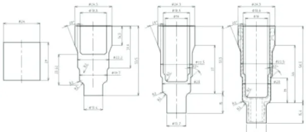
Fig. 1㦖 ㌗㣿 ❪㩺㹾㠦 㩗㣿♮⓪ 䞮㤆㰫㦮 ṖὋ
☚Ⳋ㦒⪲ 㩦㍶㦒⪲ 䚲㔲♲ 㦖 㢚㎇♲ 㩲䛞㦚 䚲㔲䞮Ⳇ, 㔺㍶㦖 ┾㫆 ṖὋ㦚 㥚䞲 䂮㑮⯒ ⋮䌖
⌎┺.┾㫆 䂮㑮㭧 ㌗┾㦮 14.5mm⓪ ┾㫆 䤚 Ṗ Ὃ㦚 㥚䞲 㾲㏢㦮 䂮㑮㧊┺. ┾㫆 㢚⬢ 䤚 㼊㩗㦖 12538.86mm
3
㧊┺.ٻ
G
Fig. 1 Dimensions of product and forging
#
515# ⚲Ữඟ⢿㘞⇇#
㧎㩳䎆 䞮㤆㰫㦮 㽞₆㏢㨂 䋂₆⓪ Ø26*L29 㧊 Ⳇ, ⶒ㎇㦖 SUS410 㧊ἶ 㥶☯㦧⩻㔳㦖 ┺㦢ὒ ṯ
┺[5].
[MPa] (1)
⌟Ṛ┾㫆 㥶䞲㣪㏢䟊㍳ 㔲 㿫╖䃃㦒⪲ 䟊㍳䞮 㡖ἶ, Fig. 2⓪ 㧎㩳䎆 䞮㤆㰫㧊 䞲⻞㦮 Ὃ㩫㦒⪲
㎇䡫㧊 Ṗ⓻䞲㰖 㡞䁷䞮₆ 㥚䟊 䟊㍳䞲 ἆὒ⯒
⽊㡂㭖┺. ⁎ ἆὒ ㌗┾㠦 ₆㭖䂮㑮 14.5mm
⯒ 㿿㫇㔲䋺㰖 ⴑ䞲, 10.5mmṖ ㎇䡫♮⓪ ἆ䞾㧊
㌳䞮㡂 Ὃ㩫 㿪ṖṖ 䞚㣪䞮┺⓪ ộ㦚 䢫㧎䞶 㑮 㧞㠞┺. Ὃ㩫 㿪Ṗ㠦 ➆⯎ ṖὋἓ䢪⪲ ㎇䡫㎇
G G
G G G G
Billet Forging finish Zoom up
Fig. 2 Longitudinal dimension defect of upper part at
one-stage forging
ٻٻ ٻ ٻ ٻ ٻ ٻ ٻ ٻ ٻ
G G G G G
ٻ
G
G
ٻBillet First forging Forging finish Zoom up
Fig. 3 Diametral dimension defect of upper part at
two-stage forging
㧊 㣿㧊䞮㰖 ⴑ䞮⸖⪲ ㏢⚪ 㻮Ⰲ⯒ 䟊㍲ ┺㦢 Ὃ 㩫㦚 㰚䟟䞲┺.
Fig. 3㦖 Ὃ㩫㦚 㿪Ṗ䟊 ㎇䡫䟊㍳㦚 㔺㔲䞮㡖⓪◆,
㌗┾ ⌊ἓ㦮 ₆㭖䂮㑮 Ø16mm⯒ ⍮⓪ Ø19.8mm Ṗ ㎇䡫♮⓪ ἆ䞾㧊 ㌳䞮㡖┺. ἆ䞾㦚 㩲Ệ䞮₆ 㥚䟊㍲⓪ ㌗┾㦮 ㎇䡫㦚 1㹾 Ὃ㩫㠦㍲ 㢚㎇㔲 䋺⓪ ộ㧊 䞚㣪䞮┺.
ٻ
516# ᶢඟ⢿㘞⇇#
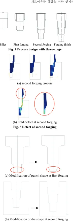
㞴㠦㍲㦮 ṗ 㡞゚ ₆㽞䟊㍳ἆὒ⯒ 䏶╖⪲ Fig. 4 㦮 ㌞⪲㤊 Ὃ㩫㍺Ἒ㞞㦚 㩲㔲䞮㡖┺.
㩲㔲♲ Ὃ㩫㍺Ἒ⯒ ₆㽞⪲ 䟊㍳ 㔲 2㹾 Ὃ㩫㠦
㍲ ㎇䡫ἆ䞾㧊 ㌳䞮⓪◆, Fig. 5(b)⓪ 㩲䛞㦮 ἆ 䞾㦚 ┾㩗㦒⪲ ⽊㡂㭒ἶ 㧞┺.
Fig. 5(b)㦮 ἆ䞾㦖 1㹾 Ὃ㩫 㢚⬢ 䤚 Fig. 5(a)㠦
㍲㢖 ṯ㧊 2㹾 Ὃ㩫㦚 㰚䟟䞾㠦 ➆⧒ 㩧䧞⓪ ἆ䞾 㧊 ㌳䞲┺. 㞚⧮㦮 ⚦ Ṗ㰖㦮 㑮㩫⻫㦚 㩲㔲 䞲 㧊㥶⓪ Fig. 5(b)㦮 ἆ䞾㦚 䟊㏢䞮₆㥚䟊, 1㹾
ഷڌڔډړٻ ڌڋډڐٻ
穢穢剳暒昷儆击穟箒滆V洢YW劒G 洢[笾SGYWXX噊VY`ZG
G
G
Billet First forging Second forging Forging finish
Fig. 4 Process design with three-stage
G G G G
(a) second forging process
G
(b) Fold defect at second forging
Fig. 5 Defect of second forging
G G G G G G G
(a) Modification of punch shape at first forging
G G G G G G
(b) Modification of die shape at second forging
Fig. 6 Modification of punch and die shapes at each
forging
G G
(a) First forging
G (b) Second forging
G (c) Forging finish
Fig. 7 Distributions of effective strain and load at first process method
Ὃ㩫 䤚 2㹾 Ὃ㩫 㰚䟟Ṛ㠦 ㏢㨂㦮 㥶☯㦚 㢂
⯊Ợ 㥶☚䞮Ệ⋮, 1㹾 Ὃ㩫㠦㍲ 㩚 㞫㿲⨟㦚 㯳 Ṗ㔲䌊㦒⪲㖾 ⹎Ⰲ ㎇䡫䞲 ㌗┾Ṗ ⁞䡫㞞㦒⪲
㥶㧛 ♮⓪ộ㦚 㰖䞮₆ 㥚䟊 Ỗ䏶♮㠞┺.
51614# ⋂⢿ᓆ# ⣆4ඟ⢿#
㑮㩫♲ 㩲1Ὃ㩫㦖 Fig. 6(a)㠦 ⋮䌖⋲ ộ㻮⩒ 1㹾 Ὃ㩫㦮 䗖䂮⯒ 2㹾 Ὃ㩫ὒ ☯㧒䞲 䡫㌗㦒⪲ Ⱒ✺
ἶ, Fig. 6(b)㠦㍲ 2㹾 Ὃ㩫 ⁞䡫㦮 䡫㌗㦚 㑮㩫䞮 㡖┺.
Fig. 7㦖 䗖䂮㢖 ⁞䡫 䡫㌗㦚 㑮㩫䞲 䤚 ṗ Ὃ㩫 㠦㍲㦮 㥶䣾⼖䡫⮶ὒ 䞮㭧㦚 ṗṗ ⽊㡂㭒ἶ 㧞┺.
G
Y
Y`[GV穢剳暒昷儆击穟箒滆V洢YW劒G 洢[笾SGYWXX噊G
G G G G G G G
Fig. 8 Modification of die shape at first forging
G G
(a) First forging
G
(b) Second forgingG
(c) Forging finishFig. 9 Distribution at effective strain and load at second process method
1㹾 Ὃ㩫㠦㍲ 䞮㭧㦖 263.0ton㧊 㧧㣿䞲┺. 1㹾 Ὃ 㩫㠦㍲ Ⱎ㰖Ⱏ ┾Ἒ㠦 䞮㭧㧊 ỿ䧞 㯳Ṗ䞲 㧊 㥶⓪ ⹖䘦┾㫆⪲ Ὃ㩫㦚 㑮䟟䟞₆ ➢ⶎ㧊Ⳇ, 2㹾 Ὃ㩫ὒ 3㹾 Ὃ㩫㦖 Ṳ䡫┾㫆⪲ 㑮䟟䟊㍲ ⌄㦖 䞮㭧㧊 㧧㣿䞮㡖┺. 1㹾 Ὃ㩫, 2㹾 Ὃ㩫 3㹾 Ὃ 㩫㌂㧊㠦⓪ ㏢⚪㦚 㔺㔲䞾㦒⪲ 㧪⮮⼖䡫㦚 㩲Ệ 䞲 䤚 䟊㍳㦚 㑮䟟䞮㡖┺.
51615# ⋂⢿ᓆ# ⣆5ඟ⢿#
㑮㩫♲ 㩲2Ὃ㩫㦖 1㹾 Ὃ㩫 ⁞䡫 䡫㌗㦚 㑮㩫
G
Fig.10 Optimal process design for precision cold forging of injector housing
G
+
Fig.11 Products of forging at each stage
䞮⓪ ⻫㦒⪲, Fig. 8㠦㍲ ⽊⓪ ộὒ ṯ㧊 ₆㫊㦮 Ὃ㩫㠦㍲ 䞮┾㦮 ₎㧊⯒ ⓮⩺ 㩚 㞫㿲⨟㦚 㯳Ṗ㔲䋺☚⪳ 㑮㩫䞮㡖┺. 㧊䤚 2㹾 3㹾 Ὃ㩫 㦖 Fig. 4㠦㍲ 㩲㔲♲ Ὃ㩫㍺Ἒ⯒ ₆㽞⪲ 䟊㍳㦚 㑮䟟䞮㡖┺.
Fig. 9⓪ ṗ Ὃ㩫㠦㍲㦮 㥶䣾⼖䡫⮶ὒ 䞮㭧㦚 ⽊ 㡂㭒ἶ 㧞┺. 1㹾 Ὃ㩫㦮 ἓ㤆 254ton㦮 䞮㭧㧊 㧧 㣿䞲┺. ⡦䞲, 䡚㨂 㔺䠮㦚 㥚䞲 ⽊㥶㧻゚㦮 㣿⨟
㧊 500ton 䝚⩞㓺㧊⸖⪲, 䟊㍳㦮 䌖╏㎇ Ỗ㯳㦚 㥚䟊㍲⓪ 㿿䞮┺ἶ 䕦┾♲┺.
㑮㩫♲ 㩲1Ὃ㩫ὒ 㩲2Ὃ㩫 ⳾⚦, 㩲䛞㦮 ㎇䡫㠦
⓪ ⶎ㩲Ṗ 㠜㠞㦒⋮, ₆㫊㦮 䗖䂮㢖 ⁞䡫㦮 㑮㩫 㦚 㾲㏢䢪䞮Ⳋ㍲ 㩚 㞫㿲⨟㦮 㯳ṖⰢ㦒⪲ ἆ䞾 㦚 㩲Ệ㔲䋾 㑮㩫♲ 㩲2Ὃ㩫㦮 ㍺Ἒ㞞㧊 㡗♲
Fig. 10㧊 㾲㩗㦮 Ὃ㩫㍺Ἒ ⻫㧊⧒ἶ 㩲㔲䞶 㑮 㧞Ỷ┺.
61# ⠢⣇㇚# 㘂❚⩿# ᎒⤚⎎㚂# Ჹ# Ḯ⇇#
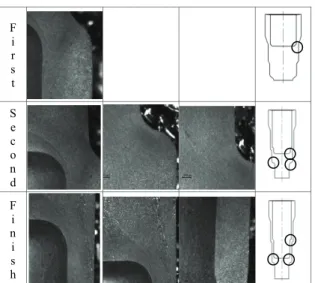
Fig. 11㦖 Fig. 10㠦㍲ 㩲㔲䞲 㾲㩗 Ὃ㩫☚⯒ 䌫㦒⪲ ㌳㌆䞲 㧎㩳䎆 䞮㤆㰫㦚 ṗ Ὃ㩫⼚⪲ ⽊ 㡂㭒ἶ 㧞┺. 㔲㩲䛞㦚 ㌳㌆䞮⓪◆ 䔏⼚䞲 ⶎ㩲㩦 㦖 ἂ♮㰖 㞠㞮┺. 㧎㩳䎆 䞮㤆㰫㦮 ⌟Ṛ┾㫆 Ὃ㩫 䤚 ㏢㨂㦮 㥶☯㎇ὒ ἓ☚⯒ 䁷㩫䞮⓪ ộ㦖 㩲䛞㦮 ἆ䞾㦚 䢫㧎䞮⓪◆ ⰺ㤆 㭧㣪䞲 㡃䞶㦚 䞲┺. Fig. 12⓪ ṗ Ὃ㩫⼚ 䟊㍳ 㔲 ⼖䡫⮶㧊 ⏨㦖
穢穢剳暒昷儆击穟箒滆V洢YW劒G 洢[笾SGYWXX噊VY`\G
G
F i r s t
G
G
S e c o n d
G G G
G
F i n i s h
G G G
G
Fig.12 Flow patterns of products at each forging
ٻ
Photograph Position Hardness(kg/mm
2
)F i r s tٻ
ٻ
1 158
2 158
3 150
S e c o n dٻ
ٻ
1 130
2 159
3 158
F i n i s hٻ
ٻ
1 114
2 143
3 130
Fig.13 Hardness measurement of products at each forging
㡗㡃㦮 ㏢㨂㥶☯㎇㦚 ⽊₆ 㥚䞮㡂 㔲㩲䛞㦚 ㌳㌆
䞲 䤚 㡆Ⱎ䞮㡂 㹣㦖 ㌂㰚㧊┺. 㩲䛞㦮 㩧䧮㧊⋮
Ἇ䂾㦖 ⽊㧊㰖 㞠⓪┺
Table 1 improvement Material Utilization
Billet(mm) Volume(mm3
) Note Cutting Ц26.4 × 71.7ٻ
39248Forging Ц26.0 × 29.0
ٻ
15397 60%↓#
Fig. 13㦖 㾲㫛㩲䛞㦮 㩗㣿 㔲 㦧⩻㧊 㰧㭧㩗㦒
⪲ ㌳♮⓪ 㥚㠦 ╖䞮㡂 ṗ Ὃ㩫⼚ Brinell ἓ
☚Ṩ㦚 ⽊㡂㭖┺.
# 71# ൚# ᤊ#
㧎㩳䎆 䞮㤆㰫㦮 ⌟Ṛ┾㫆Ὃ㩫㦚 㥶䞲㣪㏢䟊㍳
䝚⪲⁎⧾㧎 DEFORM-2D⪲ 䟊㍳䞮㡂 ┺㦢㦮 ἆ⪶
㦚 㠑㦚 㑮 㧞㠞┺.
(1) ₆㫊㦮 㩞㌃Ὃ㩫㦒⪲䎆 ⌟Ṛ┾㫆Ὃ㩫㦒⪲
⼖ἓ䞾㦒⪲㖾 㟓60%㦮 㤦㨂⬢Ṗ 㩞Ṧ♮㠞┺.
(2) Deform-2D⯒ 㧊㣿䞮㡂 㩚㌆⳾㌂⯒ 䞲 䤚 㔲 㩲䛞㦚 ㌳㌆䞾㦒⪲㖾 ἆ䞾㦚 㩲Ệ䞮ἶ, 㾲㩗 Ὃ㩫
㍺Ἒ⯒ 㢚㎇䞮㡖┺.
(3) 㩲䛞㦮 㥶☯㎇ 䁷㩫㠦㍲⓪ ⹎ἆ㥷ὒ ⹎㿿㰚 㩧䧮㧊 ⽊㧊㰖 㞠㞮┺. ἓ☚䁷㩫㠦㍲⓪ 㩲䛞㠦 䞚 㣪䞲 ṫ㎇㧊 䢫⽊♮㠞┺.
Ⳣ ඊ ᯢ 㙶
[1] D. J. Kim, B. M. Kim, 1999, Process Design to Prevent Internal & External Defects of Cold Extruded Products with Double Ribs, Trans. Mater.
Process., Vol. 8, No. 6, pp. 312~619.
[2] Y. S. Chang, J. H. Choi, B. D. Ko, H. Y. Lee, B. B.
Hwang, 2000, A Study on the Process Sequence Design of a Short-Neck Flange, J. Kor. Soc. Process.
Engineering., Vol. 17, No. 6, pp. 127~134.
[3] DEFORM User’s Manual V9.1, Scientific Forming Technologies Coperation.
[4] D. C. Ko, B. M. Kim, J. C. Choi, S. W. Oh, 1996, Process Sequence Design in Cold Forged Part of Hub, Trans. Kor. Soc. Mech. Eng. Vol. 20, No. 11, pp. 3387~3397.
[5] K. H. Park, H. T. Yeo, K. D. Hur, 2004, Forming Process Design of Fuel Injector Housing by Response Surface Method, Proc. Kor. Soc. Tech.
Plast. Conf., pp. 311~314.