1. INTRODUCTION
Global Positioning System (GPS) (Kaplan & Hegarty 2006) is one of the Global Navigation Satellite Systems (GNSS) which has been most widely used in the world. GPS was originally invented and used for military purposes. Because the military GPS is encrypted and authenticated, civilians could not use GPS. However, GPS was opened up for civilian use after the KAL007 accident in 1983, and since then civilian GPS has been used in various business and social contexts. The initial civilian GPS had Selective Availability and was vulnerable to positioning and navigational errors but since these errors have been removed, the accuracy and precision of civilian GPS has improved.
These days interest in autonomous systems like drones and autonomous vehicles has increased, and an absolute positioning system is vital for trustworthy navigation
Ranging Performance for Spoofer Localization using Receiver Clock Offset
Byung-Hyun Lee
1, Seong-Hun Seo
2, Gyu-In Jee
2†, Dong-Jin Yeom
31
EW R&D Center, Hanwha Thales, Yongin 17121, Korea
2
Department of Electronics Engineering, Konkuk University, Seoul 05029, Korea
3
RF Systems Technology Directorate, Agency for Defense Development, Daejeon 34186, Korea
ABSTRACT
In this paper, the performance of ranging measurement, which is generated using two receiver clock offsets in one receiver, was analyzed. A spoofer transmits a counterfeited spoofing signal which is similar to the GPS signal with hostile purposes, so the same tracking technique can be applied to the spoofing signal. The multi-correlator can generate two receiver clock offsets in one receiver. The difference between these two clock offsets consists of the path length from the spoofer to the receiver and the delay of spoofer system. Thus, in this paper, the ranging measurement was evaluated by the spoofer localization performance based on the time-of-arrival (TOA) technique. The results of simulation and real-world experiments show that the position and the system clock offset of the spoofer could be estimated successfully.
Keywords: GPS, spoofing, spoofer localization, anti-spoofing, TOA
performances. However radio navigation like GPS is vulnerable to high-level environmental noise or intentional signal interference such as jamming and spoofing. In particular, jamming or spoofing is a serious threat to positioning and navigation performance. Jamming is where a jammer transmits a stronger signal than the GPS signal to interrupt successful navigation and decrease the positioning performance. However, spoofing is a more serious problem than jamming. In the case of military GPS, as the P-code is encrypted, the code could not be generated. So, the main form of spoofing is where a spoofer receives the authentic GPS signal and re-radiates the signal to the target receiver with a time delay. In the case of civilian GPS, as the C/
A code is open to the public, an intentional spoofing signal could be generated by a spoofer to guide the target receiver to calculate its position in a way different from its true position based on the authentic GPS signal (Seo et al.
2015). Also, the re-radiate spoofing form can be executed in the civilian GPS spoofing environment. The point of this spoofing issue is that when the target receiver receives both of the spoofing signals, it is successfully deceived. For this reason, spoofing is the most serious problem with regard to Received July 25, 2016 Revised Aug 03, 2016 Accepted Aug 05, 2016
†
Corresponding Author E-mail: [email protected]
Tel: +82-2-450-3070 Fax: +82-2-450-5235
138 JPNT 5(3), 137-144 (2016)
GPS positioning and navigation.
Anti-spoofing techniques can be categorized into detection, mitigation, and spoofer localization. Spoofing detection and mitigation prevent the receiver from calculating an erroneous position. Humphreys et al. (2008) have presented an analysis about the effect of spoofing on GPS receiver channels and anti-spoofing methods. Others have suggested a spoofing detection method that takes advantage of spatial information using a single difference in the carrier phase between two antennas (Montgomery et al. 2009, Psiaki et al. 2014). Additionally, various detection methods are researched (Konovaltsev et al. 2013, Jafarnia- Jahromi et al. 2015, Lim et al. 2015, Radin et al. 2015).
However, detection and mitigation are passive methods to deal with spoofing attacks. So, a more active solution such as spoofer localization is required. Until now, some jammer localization methods have used time-difference-of-arrival (TDOA) and hybrid TDOA/angle-of-arrival (Lindström et al. 2007, Bhatti et al. 2012, Cetin et al. 2014, Lim et al. 2014).
In these cases, array processing has been used for localizing the jamming signal source.
In this paper, the spoof signal is detected and identified by using multi-correlators and multi-receivers. After that, both authentic and spoofing signal is tracked respectively.
Through the authentic and the spoofing signal information, the range measurements for spoofer localization are calculated. Using these range measurements, time-of- arrival (TOA) based spoofer localization becomes possible.
Then, the performance of spoofer ranging measurements (SPR) is analyzed and verified in simulation and real-world experiments.
2. RANGING MEASUREMENTS
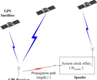
For the TOA based spoofer localization, range measurements should be generated. This section describes the spoofing environment in which the received RF signal contains an authentic GPS and counterfeit spoofing signal as shown in Fig. 1. Also, this section describes the receiver clock offsets that can generate the range measurements for spoofer localization.
2.1 Spoofing Environment
It is hard to operate a spoofed receiver (Im et al. 2013). A jamming attack, such as a continuous wave and wideband noise jamming attack, causes the receiver to lose the tracking signals, and the receiver then engages in a re- acquisition process. If the spoofer transmits the spoofing
signal at this moment, then a receiver without anti-spoofing defense can be easily spoofed. So, we have assumed that every channel of the receiver is spoofed under these circumstances.
As shown in Fig. 2, a spoofer receives the authentic GPS signal and synchronizes its clock with GPS time. Then, the spoofer acquires the navigation data and generates the spoofing signal which deceives the target receiver into calculating the spoofer intended position. After this process has been completed, the generated signal is transmitted to the target receiver and the target receiver receives both the authentic GPS and spoofing signal.
The transmitted spoofing signal has an offset to the authentic GPS time. This offset, which is defined in this paper as a spoofer clock offset ( ∆ t
spoofer), can be modeled as the sum of the spoofer system delay and an unknown delay. The spoofer system delay indicates the clock error of the signal generator from the GPS satellite clock and the internal delay up to the signal transmission.
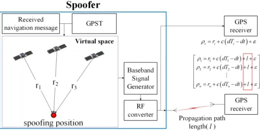
Fig. 2 shows the environment of the spoofer. The spoofer has a GPS receiver and a signal generator, so it can be synchronized with GPS time and can generate a spoofing signal with a live navigation message that is equivalent to an authentic GPS signal. The results of the spoofing signal processing before transmission consist of the pseudo-range,
( )
i
r c dT dt
i iρ = + − + ε (1)
where ρ
iis pseudo-range of the satellite i, r
iis the virtual geometric range from the satellite to the spoofed position, dT
iis the satellite clock error, dT is the receiver clock offset.
The pseudo-ranges of the received spoofing signal at the GPS receiver are shown in Eq. (2).
Fig. 1. Spoofing environment.
( )
i
r c dT dt l
i iρ = + − + + ε (2)
where l is propagation path length from spoofer to receiver.
If the navigation filter uses these pseudo-ranges, the path length l would be estimated as the receiver clock offset because l is common to every pseudo-range. The receiver will be spoofed because the navigation solution will be the position intended by the spoofer (Kaplan & Hegarty 2006). In addition, the receiver calculates the clock offset of the spoofing signal that has a path length delay. Thus, if it is possible to simultaneously track the spoofing and the authentic GPS signal, the ranges between the spoofer and the receiver can be measured using the results of the navigation filter of the spoofing and authentic GPS signals.
2.2 Ranging Measurement Modeling
Simultaneous tracking of the authentic and spoofing signal in one channel and signal identification are essential functions to generate ranging measurements. An authentic
and a spoofing signal can be simultaneously tracked using the multi-correlator (Broumandan et al. 2012, Moon et al. 2013). Since there are two signals in one channel, the next step is signal identification which can be performed by applying a spoofing detection technique to each of the signals (Swaszek & Hartnett 2013, Psiaki et al. 2014).
Thus, in this paper, it is assumed that simultaneous signal tracking and signal identification using multi-correlators and multi-antennas are possible in order to easily evaluate the performance of the ranging measurements. Fig. 3 shows the signal processing flowchart at one node.
After the identification step, the navigation filter calculates the position and the receiver clock offset using grouped authentic and spoofing signals. The pseudo-range of the spoofing signal is shown in Eq. (3).
( ) (
2) (
2)
2, s s s
spoof i xspoofed xi yspoofed yi zspoofed zi c dtspoof
ρ
= − + − + − + ⋅(3)
where, ρ
spoof,iis the pseudo-range of the spoofing signal of the satellite i, x
spoofed, y
spoofedand z
spoofedare the intended position of Fig. 2. Pseudo-ranges of spoofing environment.
Fig. 3. Pseudo-ranges of spoofing environment.
140 JPNT 5(3), 137-144 (2016)
the spoofer, dt
spoofis the receiver clock offset of the spoofing signal which is a state of navigation filter, c is the speed of light. The dt
spoofcontains the propagation path length and the spoofer delay, so it can be modeled as shown in Eq. (4).
( ) ( ) ( ) ( )
spoof GPS
l t
spooferGPST t GPST t t t
= + c + ∆ (4)
where GPST
spoofis the receiver time of the spoofing signal in GPS time coordinates, and GPST
GPSis the receiver time of the authentic GPS signal, Δt
spooferis the spoofer clock offset described in 2.1. It is important to consider not the receiver clock offset but the GPS time coordinate because of the localization problem of a meaconing that differs from authentic GPS time.
Using Eq. (4), the ranging measurements (R
j(t)) at node j can be expressed as Eq. (5).
( ) ( ( ) ( ) ) ( ( ) ( ) )
( ) ( )
( )
( )
2 2
, ,
2 ,
GPS j spoofer GPS j spoofer
j
GPS j spoofer
spoof
x t x t y t y t
R t z t z t
c t t
− + −
= + −
+ ⋅ ∆
(5)
where x
GPS,j, y
GPS,j, z
GPS,jare the position at node j which is the result of the grouped authentic GPS signal, x
spoofer, y
spoofer, z
spooferare the spoofer position which is the result of spoofer localization. In Eq. (5), the receiver clock offset is eliminated, and this means that the grade of the receiver clock does not affect the ranging performance of the spoofer localization.
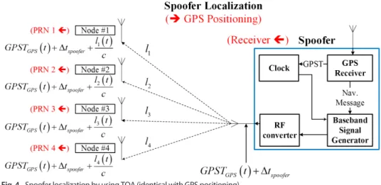
2.3 Spoofer Localization
To estimate the position of the spoofer in the previously defined spoofing environment, it is necessary that the target receiver has the function to track both the authentic
GPS and the spoofing signal simultaneously. From Eq.
(5), there are four unknowns for the spoofer localization (x
spoofer, y
spoofer, z
spoofer, Δt
spoof), so four nodes are required to solve the problem. The spoofer delay (Δt
spoofer(t)) is unknown but is common to every node. Thus, the position and spoofer delay could be estimated by TOA using the ranging measurements (R
j(t)) (Fig. 4).
3. EXPERIMENTAL RESULTS
To analyze and verify the presented ranging measurements for spoofer localization, a simulation and real-world test were conducted. The results are based on the GPS L1 C/A signal processing.
3.1 Simulation Results
A simulation was performed using a software-based GNSS signal generator that generates signals at the intermediate frequency (IF) level (Im & Jee 2014). For convenience, the following are assumed:
1) Every node can receive a spoofing signal.
2) Every node can track and identify both the authentic and the spoofing signal.
3) There are no other error components (multipath, signal block, etc.).
In this simulation, Fig. 5 shows that all the nodes and spoofer are static. Additionally, Fig. 6 presents that the positioning results of the nodes can be estimated by the generated GPS signal from the software-based GNSS signal generator.
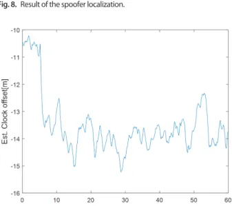
Fig. 7 presents the simulation result of the generated
ranging measurements, and Figs. 8 and 9 show the results
of the spoofer localization. As the root-mean-square-
Fig. 4. Spoofer localization by using TOA (identical with GPS positioning).
error (RMSE) of the spoofer positioning is 1.575 m, the performance of the ranging measurements is relatively
reasonable and accurate when considering the spoofing environment as shown in Table 1.
3.2 Real-world Experimental Results
To conduct a feasibility test in a real environment, we transmitted the generated spoofing signal by using a software-based signal generator using an IF to RF converter (Labsat3) and signal transmitter. The receivers (nodes) receive both the live GPS signal and the spoofing signal (Fig.
10). For the performance analysis of ranging measurements, three nodes are used for the spoofer localization in the real- world experiment (assuming that the height is known).
Table 1. Accuracy of ranging measurements and localization.
Node 1 Node 2 Node 3 Node 4 Localization
RMSE [m] 1.054 0.805 0.866 0.709 1.575
Fig. 5. Simulation environment.
Fig. 7. Accuracy of the generated ranging measurements (R).
Fig. 6. Positioning result of the generated GPS signal in ENU frame.
Fig. 8. Result of the spoofer localization.
Fig. 9. Accuracy of the estimated spoofer clock offset (Δt
spoofer).
142 JPNT 5(3), 137-144 (2016)
Unlike the simulation test, the nodes are not time- synchronized. Thus, spoofer clock drift was estimated for time- synchronized ranging measurements via interpolation (Eq. 6).
( ) ( )
1 1( )
N R N R spoof spoof N
R t = l t + ⋅ ∆ c t + ∆ t ⋅ δ t (6) where, R
Nis the SPR at node N, t
R1is the time of reference node (node 1 is the reference), ∆ t
spoofis the spoofer clock drift, δt
Nis time difference between node N and reference node (δt
N= t
R1- t
RN).
In order to easily evaluate the performance of the ranging measurements, we assumed that there is no common satellite between the spoofing signal and live GPS signal to carry out signal tracking and identification (Table 2).
Figs. 11 and 12 show that the accuracy of the ranging measurements and the results of the spoofer localization in the real experiment. Table 3 presents that these results are similar to the results of the simulation and the possibility of spoofer localization using the TOA method is confirmed.
4. CONCLUSIONS
In this paper, the performance of the ranging measurements was analyzed to determine anti-spoofing effectiveness. If a UAV or UGV is exposed to a spoofing attack, then the automatic pilot system malfunction and the vehicle can be plundered by the
spoofer.
Using the receiver clock error between the authentic GPS and the spoofing signal, the ranging measurements for spoofer localization are generated. Then the TOA localization method is used and verified. To implement the TOA based localization, it is necessary that at least 4 receivers (nodes) are deployed to receive the same spoofing signal simultaneously. In addition, the spoofer clock drift should be estimated in order to achieve ranging measurement time synchronization at each node. In conclusion, the position and the system clock offset of the spoofer are estimated accurately, and spoofer localization using generated ranging measurements is possible without the hardware clock synchronizer of each node.
Fig. 10. Real experimental environment.
Fig. 11. Accuracy of generated ranging measurements (real-world test).
Fig. 12. Result of the spoofer localization (real-world test). In order to receive the spoofing signal at every node in a real test, the receivers are set in poor DOP conditions.
Table 2. Tracked Satellite numbers (PRNs) of the live GPS and spoofing signal.
PRN Live GPS signal
Spoofing signal 7, 8, 11, 16, 21, 26, 27 10, 12, 13, 15, 17, 18, 19, 24
Table 3. Ranging measurements and localization results (real-world test).
Node 1 Node 2 Node 3 Localization
RMSE [m] 0.882 0.751 0.601 1.101