Effect on Dynamic Behavior of Group Piles with Changing Thickness of Pile Cap
7
0
0
전체 글
(2)
(3)
(4)
(5)
(6)
(7)
수치
+2
관련 문서
Wald-Type Tests for Detecting Breaks in The Trend Function of a Dynamic
The effect of Combined Exercise program on Body composition, Physical fitness and thickness of subcutaneous fat in. Obese
First, after the Group Art Therapy, the scale of hopelessness depression in the test group decreased significantly in comparison with that before the group
The study conducted a study of literature and research, and in literature, the study of cosmetic behavior, nail behavior, self esteem, and
The purpose of this research is to the development and effect of the anthroposophy group art therapy program for improvement of creativity and reduction
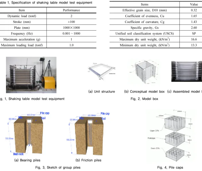
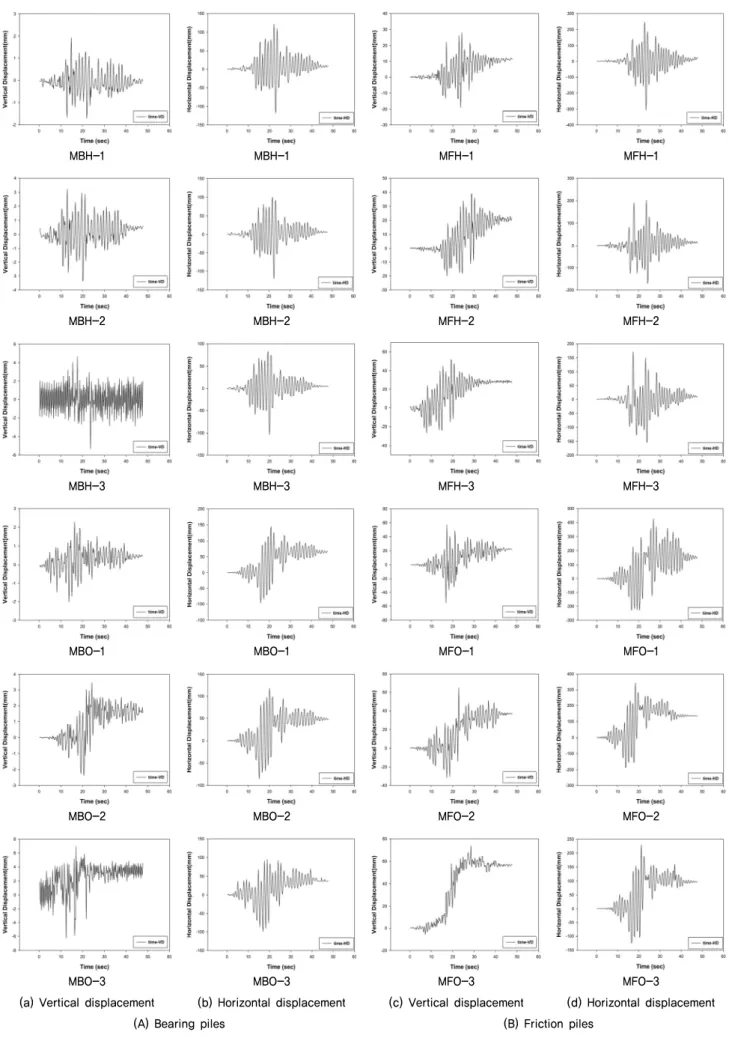
– Friction pile( 마찰말뚝 ): driven at a site where soil is not economical or rather possible to rest the bottom end of the pile on the hard stratum, Load is carried by
Piles do not support the load rather acts as a medium to transmit the load from the foundation to the resisting sub-stratum – Friction pile( 마찰말뚝 ): driven at a site where
– Friction pile( 마찰말뚝 ): driven at a site where soil is not economical or rather possible to rest the bottom end of the pile on the hard stratum, Load is carried by
