<학술논문> DOI http://dx.doi.org/10.3795/KSME-A.2014.38.5.475 ISSN 1226-4873(Print) 2288-5226(Online)
유압밸브 구동용 서보 액추에이터의 신뢰성 향상을 위한 설계 파라미터 도출
§성 백 주
*†· 김 도 식
** 한국기계연구원
Inducement of Design Parameters for Reliability Improvement of Servo Actuator for Hydraulic Valve Operation
Baek Ju Sung
*†and Do Sik Kim
** Korea Institute of Machinery & Materials
(Received April 10, 2013 ; Revised February 21, 2014 ; Accepted February 25, 2014)
- 기호설명 - S : 발열단면적
d : 액추에이터의 최대 이격거리
dl : 플런저 직경 Cm : 기자력 보정상수 Cg : 경험적 여유길이 Cp : 여유율
λ : 열소멸상수 Xi : 점적률
Key Words: Servo Actuator(서보 액추에이터), Response Characteristic(응답 특성), Design Parameter(설계 파라 미터), FEM Analysis(유한요소 해석), Performance Test(성능 시험)
초록: 유압밸브 구동용 서보 액추에이터는 항공기, 자동차의 유압시스템 그리고 산업용 유압시스템의 정밀한 작동에 중요한 장치이다. 서보 액추에이터의 신뢰성 있는 동작은 전체 유압시스템의 정밀한 제 어에 큰 영향을 미친다. 서보 액추에이터의 주파수 응답특성, 스텝 응답특성과 같은 응답특성은 액추에 이터의 성능을 판단하는 중요한 기준이 된다. 본 논문에서는 신뢰성해석을 통해 신뢰성 있는 동작과 응 답특성을 만족시키기 위한 구성 부품에 대한 분석을 실시하였다. 또한 신뢰성 있는 동작과 빠른 응답성 을 구현하기 위해 현장의 경험적 지식과 문헌 및 전문가의 전자기 이론을 통해 유압밸브 구동용 서보 액추에이터의 설계 파라미터를 도출하였다. 보빈, 요크, 플런저의 설계값, 그리고 코일의 감긴 수와 같 은 서보 액추에이터의 설계값들을 결정하는 설계 파라미터를 제안하고, 설계방정식을 통해 산출한 설계 값을 유한요소해석을 통해 타당성을 검증하였다. 또한 서보 액추에이터가 장착된 유압밸브의 성능시험 을 통해 제안한 설계 방안의 타당성을 검증하였다.
Abstract: The precision hydraulic valve is widely used in various industrial field like aircraft, automobile, and general machinery. Servo actuator is the most important device for driving the precise hydraulic valve. The reliable operation of servo actuator effects on the overall hydraulic system. The performance of servo actuator relies on frequency response and step response according to arbitrary input signal. In this paper, we performed the analysis for the components of servo actuator to satisfy the reliable operation and response characteristics through the reliability analysis, and also induced the design parameters to realize the reliable operation and fast response characteristics of servo actuator for hydraulic valve operation through the empirical knowledge of experts and electromagnetic theories. We suggested the design equations to determine the values of design parameters of servo actuator as like bobbin size, length of yoke and plunger and turn number of coil, and verified the achieved design values through FEM analysis and performance tests using some prototypes of servo actuators adapted in hydraulic valve.
† Corresponding Author, [email protected]
Ⓒ 2014 The Korean Society of Mechanical Engineers
ρ : 비저항률 q : 통전비
β : 보빈높이에 대한 코일 쌓인 두께의 비 dl : 플런저 직경
dbo : 보빈 외경 dbi : 보빈 내경
1. 서 론
서보 액추에이터는 전자기적 에너지를 기계적 운 동 에너지로 변환하는 장치로서 시스템의 단순성으 로 인해 매우 경제적인 기기이다.(1) 서보 액추에이터 는 자동차 및 항공기 산업에 필요로 하는 긴 수명뿐 만 아니라 다양한 사용 상황에 적합한 안정적인 성 능이 필요하다.(2,3) 현재 국내에서 서보 밸브를 공식 적으로 상품화해서 판매하는 곳은 없다. 밸브 바디 는 설계 및 제작이 가능하지만, 액추에이터 부분은 전자기적 지식과 현장에서 축적된 경험적 지식이 어 우러져 설계되어야 하기 때문에 기존에 출시된 선진 제품을 그대로 모방해서 제작해도 제대로 된 성능이 나오지 않는 것이 실상이다. 이번 연구에서는 유압 밸브 구동용 서보 액추에이터의 신뢰성 있는 동작과 응답특성을 만족시키기 위한 구성 부품에 대한 분석 을 통해 신뢰성해석을 수행하였고 서보 액추에이터 의 설계값을 산출하기 위해 전자기적 이론과 경험적 지식이 결합된 설계 파라미터를 제안하고, FEM 해석 과 시제품에 대한 주요 성능시험을 통하여 타당성을 입증하였다.
2. 서보 밸브
Fig. 1 은 서보 밸브의 간략한 구조도이다. 전자 장 형성을 위한 코일, 기계적 운동을 하는 플런저,
1:valve body, 2:Spool, 3:Sleeve, 4:Spool return spring, 5:Solenoid, 6:Plunger,
7:Plunger return spring, 8:LVDT Fig. 1 Structure of servo valve
운동을 안내하는 베어링, 그리고 유량제어를 위한 스풀 및 슬리브로 구성되어 있다.
3. 고장 분석 자료
3.1 Failure Modes and Mechanisms Analysis
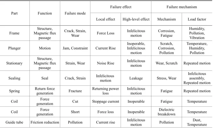
대상품의 신뢰성해석을 위해서는 우선 고장분석 이 수행되어야 한다.(4~6) 고장분석의 수행의 첫 번 째 단계는 FMMA 이다. 이 단계에서는 대상품의 주요 부품들을 나열하고, 해당 부품의 기능을 정 리한 뒤, 각 부품에서 발생되는 고장모드와 고장 발생으로 인해 시스템에 미치는 영향을 분석하게 된다. Table 1 은 서보 밸브 조립체에 대한 FMMA 결과물이다.
3.2 Failure Modes, Effects, and Criticality Analysis 고장분석 수행의 두 번째 단계에서는 앞서 수행 한 FMMA 결과를 토대로 부품의 고장형태, 영향 과 더불어 고장 발생 원인 및 고장 발생의 빈도와 심각성을 평가하는 FMECA 을 작성하였다. Table 2 는 서보 밸브 조립체에 대한 FMECA 결과물이다.
3.3 2-Stage Quality Function Deployment
앞서 수행한 FMMA 와 FMECA 의 내용을 토대 로 신뢰성평가 시험항목을 결정하기 위한 2-Stage QFD 를 작성하였다. 2-Stage QFD level 1 에서는 고 장분석자료를 통해 정리 및 분석된 주요 부품들에 대한 요구품질 및 성능을 정리하고 해당사항에 대 해 중요도를 매기게 된다. 2-Stage QFD level 2 에서 는 각 요구품질 및 성능을 확인하기 위한 시험항 목들에 대한 중요도를 매기고, 우선순위를 정하게 된다. Table 3 과 Table 4 는 2-Stage QFD 를 수행한 결과이다.
Fig. 2 Structure of servo actuator
Table 1 FMMA(Failure Modes and Mechanisms Analysis)
Part Function Failure mode
Failure effect Failure mechanism
Local effect High-level effect Mechanism Load factor
Frame
Structure, Magnetic flux
passage
Crack, Strain,
Wear Force Loss Infelicitous motion
Corrosion, Fatigue
Humidity, Pollution, Vibration
Plunger Motion Jam, Constraint Current Rise
Inoperable, Infelicitous motion
Scratch, Corrosion,
Pollution
Temperature, Humidity,
Pollution
Stationary
Structure, Magnetic flux
passage
Strain, Wear Noise Rise Infelicitous
motion Wear, Scratch Repeated motion
Sealing Seal Crack, Strain Infelicitous
motion Leakage Stress, Wear
Infelicitous assembly, Repeated motion Spring Return force
generation Fracture Returning power loss
Infelicitous
motion Fatigue Repeated motion
Coil Force
generation Cut Stoppage current Inoperable Fatigue Temperature
Coil Force
generation Short Force loss Inoperable Dielectric
breakdown Temperature Guide tube Friction reduction Pollution Current rise Infelicitous
motion Pollution Dust,
Temperature
Table 2 FMECA(Failure Modes, Effects and Criticality Analysis)
Part Function Failure mode
Failure effect Failure mechanism Criticality
Local effect High-level
effect Mechanism Load factor Frequency Severity Criticality
Frame
Structure, Magnetic flux passage
Crack, Strain, Wear
Force Loss Infelicitous motion
Corrosion, Fatigue
Humidity, Pollution, Vibration
Medium Medium 5
Plunger Motion Jam, Constraint
Current Rise
Inoperable, Infelicitous motion
Scratch, Corrosion,
Pollution
Temperature , Humidity,
Pollution
Medium High 7
Stationary
Structure, Magnetic flux passage
Strain, Wear Noise Rise Infelicitous motion
Wear, Scratch
Repeated
motion Low Low 1
Sealing Seal Crack, Strain
Infelicitous
motion Leakage Stress, Wear
Infelicitous assembly, Repeated motion
Low Medium 3
Spring Return force
generation Fracture Returning power loss
Infelicitous
motion Fatigue Repeated
motion Low High 5
Coil Force
generation Cut Stoppage
current Inoperable Fatigue Temperature High High 9 Coil Force
generation Short Force loss Inoperable Dielectric
breakdown Temperature High High 9 Guide tube Friction
reduction Pollution Current rise Infelicitous
motion Pollution Dust,
Temperature Low High 5
Table 3 2-Stage QFD level 1 Failure mode
Requirement
Frame crack& strain Sealing wear Plunger jam& Constraint Stationarystrain &Wear Spring Strain& fracture Coil cut Coil short Guide tube Pollution
Smoothing function
of plunger ○ ○ ● ○ ● ● ● ●
Low consumption
power ▲ ○ ● ○
High attraction
force ▲ ○ ● ▲ ● ● ▲
Low temperature
rise of coil ○ ● ○ ○ ● ● ○
High insulation
resistance ● ●
Low pollution ● ▲
Low noise ● ▲
Prevention of
corrosion ● ○ ▲ ○ ○
High durability ● ▲ ○ ▲ ● ● ● ▲
failure risk 25 26 36 27 38 45 59 33
priority 8 7 4 6 3 2 1 5
Very important ●:9, Important ○:5, Normal ▲:3
Table 4 2-Stage QFD level 2 failure
mode/
risk
test item
Frame crack &strain Sealing wear Plunger jam&Constraint Stationary strain& Wear Spring Strain &fracture Coil cut Coil short Guide tube pollution status priority
25 26 36 27 38 45 49 33 Structure
test ○ ▲ 224 13
Noise test ▲ ▲ ● 429 10
Consumption
power Test ○ ○ ○ 650 6
Maintain
power test ○ ○ ○ 560 9
Starting
power test ○ ○ 405 11
Attraction
force test ○ ▲ ○ ○ ○ ○ 968 2
Temperature
rising test ▲ ● ○ 758 4
Insulation Resistance
test
● ○ 650 6
Voltage test ● ○ 650 6 High
temperature test
○ ○ ● 706 5
Low temperature
test
○ ▲ 265 12
Humidity
test ▲ ▲ ▲ ○ ● 899 3
Lift test ○ ● ● ○ ● ● ● ○ 2171 1
Very important ●:9, Important ○:5, Normal ▲:3
4. 설계 파라미터
액추에이터에 대한 신뢰성을 확보하여 필요한 성능 을 얻기 위해서는 앞에서 수행한 고장분석자료에서 분석된 구성부품들에서 발생할 수 있는 고장요인을 설계 파라미터로 취급해서 설계해야 한다. Table 5 는 서보 액추에이터에 대한 주요 설계 파라미터가 포함 된 방정식이다. 이 수식들은 서로 물고 물리는 상호 연관적 관계에 있다. 액추에이터에서의 주요 전기적 고장은 솔레노이드에서 발생하는데, 상당 부분이 온 도상승을 고려하지 않은 설계를 하기 때문이다.(7~10) 본 논문에서는 온도상승을 고려한 설계방정식을 도출 하여 전기적 문제점을 보완하였다. 그리고 필요로 하
Table 5 Design equations
Items Design equations Attraction force
2
0
2 [ ] B S
F N
µ
= •
Design coefficient 0 2
2
m f
K =µ • •S U
Max. attraction force max 2 f f
F K S
= [N]
Min. attraction force min 2
Kf
F = d [N]
Magnetic flux density 2 2 0 min
l
B F
d µ
π
• •
= • • [T]
Magnetic motive force
0
Cm B d
U µ
= • • [V]
Inner diameter of yoke dyi =dbo+Cg[mm]
Outer diameter of yoke dyo= d2yi+Cp•dl2[mm]
Coil turn number N=nc•mc
Coil height
2
3( )
2 i f
q U
h X T
β ρ λ
• • •
= • • • [mm]
Coil mean length ( )
2
bo bi
m
d d
l π +
=
Diameter of bare wire s 2 (bo bi)
d d U
d V
ρ
• • + •
=
[mm]
Rising temperature
2 f
i
q N W
T d X w h V
ρ λ
• •
= • • • • • Equivalent resistance t 2 ( bo2 bi)
s
d d N
R
d ρ
π
• • + •
= [Ω]
Coil current
t
I V
=R [A]
Consumption power W = •V I[W]
는 100Hz 이상의 액추에이터 응답속도는 솔레노이드 만으로는 불가능하기 때문에 영구자석을 보조 자성체 로서 사용하였다. Fig. 2 는 영구자석부분을 제외한 액 추에이터의 주요 부분에 대한 구조도이다.
5. 서보 액추에이터 시제품
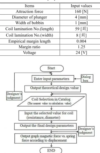
Fig. 3 은 설계방정식을 이용한 서보 액추에이터 의 설계 파라미터 산출 흐름도이다. 입력파라미터 를 넣고, 설계 과정 중 설계자의 판단으로 경험적 설계변수를 설정하여 최종 설계 파라미터를 산출 하게 된다. Table 6 은 액추에이터의 목표 사양이며, Table 7 은 설계에 이용되는 입력 파라미터이다.
Table 6 Target values
Items Target values
Voltage 24 [V]
Consumption power 55 [W]
Operation frequency 120 [Hz]
Attraction force 160 [N]
Table 7 Input parameters
Items Input values Attraction force 160 [N]
Diameter of plunger 4 [mm]
Width of bobbin 1 [mm]
Coil lamination No.(length) 59 [회]
Coil lamination No.(width) 8 [회]
Empirical margin length 0.004 Margin ratio 1.25
Voltage 24 [V]
Fig. 3 Flow chart of design program
Fig. 4 는 설계프로그램을 이용하여 산출된 설계 결과이고, Fig. 5 는 산출된 설계값을 사용하여 제 작된 서보 액추에이터 시제품이다.
Fig. 4 Results of design
Fig. 5 Prototype of servo actuator
6. FEM analysis
설계방정식을 통해 산출된 요크 내.외경, 보빈 내.
외경, 코일 감김 수 등의 액추에이터 설계사양을 입 력하여 Flux 3D 를 이용한 FEM 해석을 수행하였다.
Fig. 6 은 전류가 인가되지 않은 상태에서 액추에이터 의 자속밀도를 나타낸다. 상부와 하부에 위치한 영 구자석에서만 자속이 분포하고 있음을 알 수 있다.
Fig. 7 은 코일에 전류를 인가하여 코일에서 발생되는 자속과 영구자석에서 발생되는 자속이 합하여 왼쪽 부분에 2.2 [T]의 자속이 집중되어 플런저가 왼쪽으 로 이동함을 알 수 있다. 전류가 반대로 흐르면, 자 속은 반대쪽에 분포하여 플런저가 반대로 이동하게 된다.
Fig. 8 은 자속밀도 형성 결과에서 플런저 좌측 부 분 공극의 자속밀도 분포를 보기 위해 단면을 자른 cut plane 이다. Fig. 8 에서 7-13 은 Fig. 7 의 좌측상단에 설치된 영구자석의 잔류자속밀도, 13-24 는 그 하부의 플런저 상단 공극의 자속밀도, 28-36 은 플런저 하단 공극의 자속밀도, 38-44 는 좌측 하단에 설치된 영구 자석의 자속밀도를 나타낸다. 이들 해석모델을 통해 정격전류를 액추에이터에 흐르게 했을 때, 플런저를 이동시키는 공극의 자속밀도가 약 2.2 [T]까지 증가 하는 것을 알 수 있었다.
Fig. 6 Magnetic flux distribution at 0.0A
Fig. 7 Magnetic flux distribution at 2.2A
7. 시제품 주요 성능시험
7.1 히스테리시스 특성 시험
제작된 액추에이터의 시제품을 밸브바디에 장착하 여 완성된 서보 밸브를 사용하여 주요 성능시험을 수 행하였다. Fig. 9 는 히스테리시스 특성시험의 결과이다.
히스테리시스 특성시험은 입력에 대한 출력유량의 히 스테리시스 특성을 알아보는 시험으로 ±10V 입력에 대한 히스테리시스 특성은 1.09%로 나타났다.
7.2 흡인력 시험
Fig. 10 은 흡인력시험의 결과이다. 흡인력시험은
Fig. 8 Magnetic flux density distribution of air gap to use cut plane
Fig. 9 Magnetic flux density distribution of air gap to use cut plane
Fig. 10 Attraction force of the actuator
입력 전류에 대한 액추에이터의 흡인력을 측정하 는 시험으로 2.2A 지점에서 흡인력이 약 157N 이 측정됨을 알 수 있다.
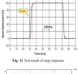
7.3 스텝응답 특성시험
Fig. 11 은 스텝응답특성시험의 결과이다. 스텝응답 특성 시험은 입력신호와 플런저의 반응시간의 차이 를 측정한다. 액추에이터에 정격전류를 인가하여 플 런저의 반응을 LVDT(Linear Variable Differential Transformer) 출력신호에 의해 검출하게 된다. Fig. 11 에서 30ms 지점에서 신호를 인가했을 때, LVDT 출 력신호 5V 가 35ms 지점에서 검출되어 응답특성이 5ms 임을 알 수 있다.
7.4 주파수 응답 특성시험
주파수 응답 특성은 서보 액추에이터의 동특성 을 알 수 있는 대표적인 성능이다. Fig. 12 는 주파 수응답특성시험의 결과이다. 주파수응답특성시험은 스텝응답특성시험과 마찬가지로 LVDT 의 출력신호 를 검출하여 측정하고, 입력신호와 플런저의 반응 시간 및 신호크기의 차이를 측정하여 Bode 선도로 서 나타낸다. Fig. 12 에서 -3dB 주파수는 189Hz,
Spool displacement [%]
Time [ms]
Fig. 11 Test result of step response
Fig. 12 Test result of frequency response
90°위상지연 주파수는 291Hz 임을 알 수 있다.
이 결과는 목표로 한 작동 주파수인 120Hz 보다 월등히 높은 수준이며, 만약 설계방정식을 통한 설계가 제대로 이루어지지 않았다면, 이러한 고속 의 주파수 응답특성은 나타나지 않았을 것이다.
8. 결 론
본 논문에서는 유압밸브 구동용 서보 액추에이 터의 신뢰성을 향상시키기 위하여 밸브 조립체에 대한 고장분석자료를 작성하고, 이를 토대로 성능 개선을 위한 설계 파라미터를 도출한 뒤, FEM 해 석과 주요성능시험을 통해 설계방정식의 타당성을 입증하였다.
(1) 선진제품을 통한 고장분석자료를 작성하여 서보 액추에이터가 필요로 하는 종합성능시험, 내 환경성시험, 수명시험 등의 신뢰성 자료를 결정
(2) 목표 사양과 시제품의 실험결과 전류대비 흡인력시험:160N/157N), 그리고 전자장 해석결과 (자속밀도:2.334T/2.2T)가 유사하게 일치하는 것을 확인함으로서 도출한 설계방정식이 타당함을 입증 (3) 서보 액추에이터 시제품을 장착한 서보밸브 의 스텝응답특성은 약 5ms, -3dB 주파수응답특성 은 189Hz, 90 위상지연 주파수는 291Hz 로서 선진 제품 수준임을 확인
(4) 향후 응답특성에 영향을 미치는 설계변수값 을 개선하여 더 높은 응답특성의 서보 액추에이터 를 설계하는 것과 수명시험을 통한 내구성능을 확 인하는 것을 진행할 예정임.
참고문헌
(References)
(1) Sung, B. J., Lee, E. W. and Kim, H. E., 2002,
“Development of Design Program for on and off type Solenoid Actuator,” Prodeedings of the KIEE Summer Annual Conference, pp. 929~931.
(2) 2008, “Reliability Assessment Technology of High- Speed and Intelligent System,” Ministry of Knowledge Economy.
(3) Arakawa, T. and Niimi, S., 2002, “Optimization Technology of Magnetic Circuit for Linear Solenoid,”
SAE Technical Paper Series, 2002-01-0565.
(4) Logistics Engineering Technology Branch Carederock div, 1998, "Hand book of Reliability Prediction Procedures for Mechanical Equipment," Naval Surface Warfare Center Carderock Division.
(5) MIL-STD-882D, 2000, Standard Practice for System Safety, Agencies of the Department of Defense, U.S.A.
(6) Bloch, H. P. and Geitner, F. K., 2012, Machinery Failure
Analysis and Troubleshooting, Gulf Publishing Company.
(7) Roter, C., 1970, Electro Magnetic Device, John Wiley
& Sons, Inc.
(8) Hydraulic and Pneumatic Lap. of KIMM, 2001,
“Development of low Consumption Power Type Solenoid Valve,” KIMM-CSI annual report.
(9) Sung, B. J., Lee, E. W. and Kim, H. E., 2004,
“Characteristics of Non-magnetic Ring for High- Speed Solenoid Actuator,” The Eleventh Biennial IEEE Conference on Electromagnetic Field Computation, Korea, p. 342.
(10) Kunio, K., 1997, “Design Concept for DC Solenoid of Pneumatic Valve,” KIMM research reporter.