1. Introduction
Coating and cathodic protection are both required to minimize external corrosion on buried metallic pipelines.
Especially in gas station located in areas with high dwell- ing density, a corrosion protection system that will enable reliable, safe and economic operation for the design life of the buried pipeline should always be paid more attention. However, the piping in gas distribution stations usually consists of a network of different size and materi- als that are interconnected through the grounding system to reduce the effects of hazardous voltages associated with lightning and fault currents in the earth. When the regional cathodic protection was applied, much of the current will tend to flow to the grounding system that is not intended for cathodic protection. What’s more, limited space and shielding effects may make the design of the cathodic pro- tection more complicated.
For example, in the mentioned gas station here, it was found that except the reinforced steel in concrete, there are four kinds of metal buried directly under earth in the gas distribution station: carbon steel, galvanized flat steel, zinc rod and graphite module. Carbon steel was for the buried pipeline and the following three are for the ground-
ing system. The buried pipeline was coated with liquid epoxy resin, having various diameters ranging from 34 mm to 1016 mm and various buried depth ranging from 0.8 m to 2 m. The other three different metals: graphite module, zinc rod and galvanized flat steel, all bare, make up the grounding system. Graphite module was mainly used for lightning protection system of buildings in the dwelling area while zinc was mainly used in the working equipment area. Graphite module was mistakenly used in this station as vertical grounding metal and directly con- nected to the buried pipeline through galvanized flat steel, only considering its low resistivity to earth while ignoring its galvanic effect on the other metals, resulting in a high risk of galvanic corrosion. In our previous work, the gal- vanic effect of copper on zinc has already been studied.
When the DC stray current exists, corrosion of metal with more negative potential will be more enhanced [1].
However, few papers have focused on the galvanic corro- sion behaviour caused by graphite on buried pipeline, es- pecially based on field investigation. In order to maintain the pipeline integrity, it is urgent to design an appropriate regional cathodic protection system for the newly built gas distribution station.
In this work, the polarization behaviour of pipeline car- bon steel, zinc and graphite module were tested to provide data information for engineering design. The result of pro-
Regional Cathodic Protection Design of a Natural Gas Distribution Station
Hu Yabo1,†, Zhang Feng2, and Zhao Jun2
1Petrochina Pipeline Company Shenyang Longchang Pipeline Survey Centre
2Petrochina Pipeline R&D Centre
(Received August 17, 2017; Revised August 17, 2017; Accepted October 09, 2017)
Regional cathodic protection has significant impact on pipeline integrity management. After risk analyses of a newly built gas distribution station constructed in an area with large dwelling density, risk score was high because of potential threat caused by galvanic corrosion. Except reinforced steel in concrete, there are four kinds of metal buried under earth: carbon steel, galvanized flat steel, zinc rod and graphite module.
To protect buried pipeline from external corrosion, design and construction of regional cathodic protection was proposed. Current density was measured with potential using potential dynamic test and boundary element method (BEM) was used to calculate current requirement and optimize best anode placement during design.
From our calculation on the potential, optimized conditions for this area were that an applied current was 3A and anode was placed at 40 meters deep from the soil surface. It results in potential range between -1.128 VCSE and -0.863 VCSE, meeting the -0.85 VCSE criterion and the -1.2 VCSE criterion that no potential was more negative than -1.2 VCSE to cause hydrogen evolution at defects in coating of the pipeline.
Keywords: regional cathodic protection, galvanic corrosion, BEM method, anodic interference
†Corresponding author: [email protected]
tection effect was simulated using a boundary element method (BEM). The possible anodic interference on main line outside the station was also discussed by calculating the earth potential gradient.
2. Estimation of Current Requirements Estimation of an appropriate current requirement for the buried metallic structure was crucial for the design process. A study of polarization curve of different buried structure was carried out. The polarization of zinc and pipeline carbon steel was carried out in the laboratory.
Prior to each experiment, the specimen surface was pol- ished to 1500 grit (SiC paper) finish, washed with distilled water, degreased with ethanol and dried in a flow of cold air. After the potential of sample became stable in the soil got from the station, the scan was carried out from the negative to positive direction at the rate of 1 mV/s.
The polarization of graphite module was carried out near the station. During the test, a constant current was applied to a single (disconnected to other structure) graphite mod- ule (0.82 m2 surface area) buried under earth. The instant off potential was recorded when the potential became unchanged. The result was shown in Fig. 1 and compared with typical polarization curve of pipeline carbon steel and zinc. It was shown that the rest potential of graphite module (-0.107 VSCE) was much more positive than the galvanized flat steel (-0.9 VSCE) and carbon steel (-0.5 VSCE). Under the driven voltage caused by different rest potential, galvanic corrosion can be expected.
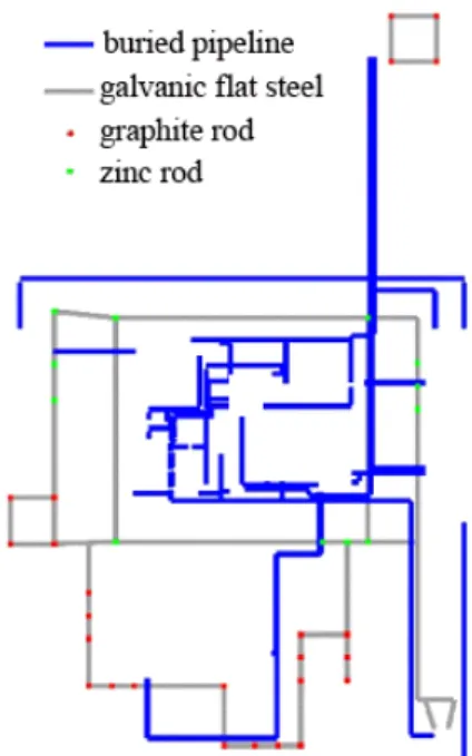
Since 1980s, following the increase in computer proc- essing power, a BEM has been widely applied to solve corrosion problems such as galvanic corrosion and catho- dic protection [2]. A BEM mrestodel in Fig. 2 based on the actual structure distribution in the gas station was
designed. In Fig. 2, the blue line represents the buried pipeline; the gray line represents the galvanic flat steel;
the green dot represents the zinc rod; the red dot represents the graphite rod. Using the polarization data got from Fig.
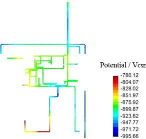
1, the calculated rest potential distribution of the mixed structure was shown in Fig. 3. Potential of pipeline near the graphite module was about -0.574 VCSE, more positive than the potential near the zinc rod being -0.892 VCSE. A field measurement was also conducted and it was found that the rest potential of a buried steel coupon was Fig. 1 Polarization curve of three different structure.
Fig. 2 Distribution of buried metallic structure in the station.
Fig. 3 Distribution of rest potential.
-0.66VCSE, the potentials of pipelines in the working re- gion range were between -0.7VCSE and -0.8 VCSE, and the potential of pipelines in the dwelling region was only about -0.53 VCSE. This was almost consistent with the data in Fig. 3 and it was obvious that the different vertical grounding metal affects distribution of potential greatly.
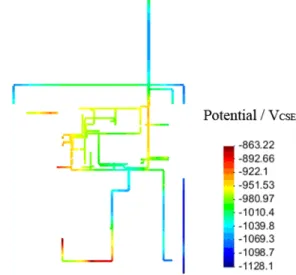
When different magnitude of current (2A and 3A) was applied on the buried structure from a supposed 40 m deep anode, the distribution of potential was shown in Fig. 4 and Fig. 5 respectively. It was obvious that poten- tial of buried pipeline near the graphite module would always be more positive than that near the zinc rod and 3A current was needed to keep potential of all the buried pipeline more negative than -0.85 VCSE.
As shown in Fig. 5, when the pipeline near the zinc rod was polarized to -1.1 VCSE, the pipeline near the graph- ite module was only -0.9 VCSE. The current consumed by different buried structure was summarized in Table 1.
Only 46% of the total current was applied on the buried pipeline and 54% of the total current was “wasted” on the grounding system. Take an already installed regional cathodic protection system for example, the soil type was mainly sand, a single graphite module would consume about 0.4 A current to be polarized to -0.85 VCSE. After about 60 graphite modules were replaced by zinc rod, the outcome of the rectifier was almost 24 A reduced. As the mentioned gas distribution station here was relatively small, an impressed current cathodic protection system may be enough to protect the buried pipeline without re- placing the graphite modules.
Fig. 4 Distribution of potential when 2A cathodic protection current was applied on the buried structure.
Fig. 5 Distribution of potential when 3A cathodic protection current was applied on the buried structure.
Table 1 Statistics of current consumed on different buried structure
Buried structure Surface area (m2) Current density
(mA/m2) Current demand (A)
Buried pipeline 83.9
(The coating was 10% damaged) 20* 1.7
Zinc rod 4.1 0** 0
Galvanized flat steel 23 20*** 1.4
Graphite module 29.1 60**** 0.6
Total 3.7
* Based on the NACE recommended value;[3]
** Assume the zinc rod consume no current;
*** Assume the zinc coating has already been corroded and treated as bare steel;
**** Based on the polarization curve in Fig. 1.
3. Design of Anode Well
The Wenner’s four-pin method was used to measure the soil resistivity at different soil layers. The Barnes method was used to calculate the layer resistivity. Take the soil layer between the depth of 30 m and 40 m for example, the soil resistance can be calculated as shown in Equation (1) :
m m
m m
R R
R hR
40 30
40
2 30
-
= p ´
r (1)
Where r represents the layer soil resistivity between 30 m and 40 m in Ω·m; hrepresents the depth of the soil layer in m; R30m represents the measured resistance at the depth of 30 m; R40m represents the measured resist- ance at the depth of 40 m; The calculated results were summarized in Table 2.
From the soil resistivity results, the anode grounding resistance would not be a big problem. However, with the depth of anode well increase, a more even potential distribution can always be expected according to common experience. The potential distribution with either a 15 m anode well or a 40 m anode well at the same place dis- charging 3 A current was shown in Fig. 6 and Fig. 7 respectively. Under the 15 m well situation, shielding ef- fect was obvious, only the pipeline adjacent to the well can achieve a potential of about -1.0 VCSE while the poten- tial at the end and next to the graphite module was still more positive than -0.85 VCSE. Several other 15 m anode well will be needed to meet the -0.85 VCSE criteria. Under the 40 m well situation, the potential range between -1.128 VCSE and -0.863 VCSE, all meet the -0.85 VCSE criteria and no potential was more negative than -1.2 VCSE to cause hydrogen evolution at defects in the coating of the pipeline.
Considering the homogeneous potential distribution and the low risk of destroy already exist buried structure with confined construction area, a 40 m deep anode well has a good priority. As a result of electro permeation and oxy-
Fig. 6 Potential distribution using a 15m anode well. Fig. 7 Potential distribution using a 40m anode well.
Table 2 Divide of soil with different resistivity
Layers Depth (m) Soil resistivity (Ω·m)
1 From 0 to10 28
2 From 10 to 20 50
3 From 20 to 30 25
4 From 30 to 40 22
Table 3 Upper limit of the current density for deep anode well
Soil type Upper limit current density (A/m2)
Very dry 1.08
Dry 1.61
Above the water line 2.15
Wet 3.22
Open well 4.95
gen blockage around the anode, the grounding resistance of deep anode well usually increased greatly with time going on. In response, an upper limit for the current den- sity that the anode can discharge at different situations was summarized in Table 3.
The underground water emerged at the depth of 15 m.
When the chosen MMO anode was buried around water, the current density should be controlled below 3.22 A/m2 and at least 1.4 m in length anode was needed. In order to provide a large current capacity for future station re-construction, five MMO anodes (1.5 m length each) were installed between the depth of 30 m and 40 m with coke surrounding them. The calculation of anode ground- ing resistance and earth potential gradient was also carried out. The grounding resistance was calculated using the following Dwight’s formula for anode that buried in- finitely deep, as shown in Equation (2):
(2)
Where Rrepresents the anode grounding resistance in Ω; r represents the soil resistivity in Ω·m; l represents the anode length in m, which was chosen as 10 m; d represents the anode well diameter in m, which was chosen as 0.219 m; t represents the buried depth of the anode in m, which was chosen as 30 m; The calculated anode grounding resistance R for 40 m deep anode well was 1.6 Ω.
Design of impressed current cathodic protection systems requires that foreign underground structures that are in the proximity of anode ground bed should not
receive current dissipated by the anode ground. J. H.
Morgan’s work revealed that pipeline can expect a considerable cathodic swing when the potential between soil around the structure and remote earth was 1.5 V, however, effect of 0.3 V soil to remote earth potential at the pipeline would be negligible in practical installations. [4] No unacceptable anodic interference will be caused by an anodic interference voltage of 0.5 V between the soil around the structure and remote earth.
Rogelio’s work revealed that the location where the potential to remote earth developed by the anode ground bed in the ground is equal to or less than 5% of the anode ground bed potential to remote earth has been regarded as the remote earth. [5]
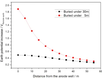
The earth potential gradient was calculated by Equation (3) with the result shown in Fig. 8.
(3)
Where Ur represents the earth potential with respect to remote earth at the distance of r from the centre of the anode well in V; I represents the magnitude of the output current in A; r represents the soil resistivity in Ω·m; l represents the anode length in m, which was chosen as 10 m; t represents the buried depth of the anode in m;
It was shown that when the anode was buried under 5m, the earth potential increase was more than 0.5 V with respect to the remote earth at the distance of 0 ~ 35 m away from the centre of anode well; However, the rise of earth potential can be less than 0.5 V at the centre of the anode well when the anode was buried under 30 m, the anodic interference on foreign buried structure can be neglected. What’s more, the earth potential gradient was much less than 5 V/m which was a personnel safe criterion. In order to control the interference of this deep anode well on main line outside the distribution station, a 40 m well with the anode buried under 30 m would be a better choice.
4. Summary
The different polarization behaviour of carbon steel, zinc and graphite reveal a high risk of galvanic corrosion for buried pipeline and a regional cathodic protection sys- tem was designed in a newly built gas distribution station.
The current requirement was about 3 A according to the BEM simulation results and a 40 m deep anode well was chosen to discharge the current.
Fig. 8 Rise of the earth potential around the anode well discharging 3 A current.
References
1. S.-j. Gao, Sen Wang, Y.-b. Hu, Z.-Z. Li, H.-L. Ji, C.-f.
Dong, and X.-q. Li, J. Univ. Sci. Technol. B., 35, 1327 (2013).
2. M. Miyasaka, K. Hashimoto, K. Kishimoto, and S. Aoki, Corros. Sci., 30, 299 (1990).
3. R. Baboian, NACE Corrosion Engineer’s Reference Book, 3rd ed., pp. 1-448, NACE, Houston (2002).
4. J. H. Morgan, Cathodic protection, 2nd ed., pp. 1-519, NACE, Houston (1993).
5. Rogelio de las Casas, Proc. NACE Conf., No. 09543Atlanta, USA