Prediction of optimal bending angles of a running loop to achieve bodily protraction of a molar using the finite element method
Objective: The purpose of this study was to predict the optimal bending angles of a running loop for bodily protraction of the mandibular first molars and to clarify the mechanics of molar tipping and rotation. Methods: A three- dimensional finite element model was developed for predicting tooth movement, and a mechanical model based on the beam theory was constructed for clarifying force systems. Results: When a running loop without bends was used, the molar tipped mesially by 9.6
oand rotated counterclockwise by 5.4
o. These angles were almost similar to those predicted by the beam theory. When the amount of tip-back and toe-in angles were 11.5
oand 9.9
o, respectively, bodily movement of the molar was achieved. When the bend angles were increased to 14.2
oand 18.7
o, the molar tipped distally by 4.9
oand rotated clockwise by 1.5
o. Conclusions: Bodily movement of a mandibular first molar was achieved during protraction by controlling the tip-back and toe-in angles with the use of a running loop. The beam theory was effective for understanding the mechanics of molar tipping and rotation, as well as for predicting the optimal bending angles.
[Korean J Orthod 2018;48(1):3-10]
Key words: Finite element method, Molar protraction, Running loop, Tip-back angle
Woon-Kuk Ryu
aJae Hyun Park
b,cKiyoshi Tai
b,dYukio Kojima
eYoungjoo Lee
fJong-Moon Chae
b,f,g,ha
Private Practice, Daejeon, Korea
b
Postgraduate Orthodontic Program, Arizona School of Dentistry & Oral Health, A. T. Still University, Mesa, AZ, USA
c
Graduate School of Dentistry, Kyung Hee University, Seoul, Korea
d
Private Practice, Okayama, Japan
e
Department of Mechanical Engineering, Nagoya Institute of Technology, Nagoya, Japan
f
Department of Orthodontics, Wonkwang University School of Dentistry, Iksan, Korea
g
Wonkwang Dental Research Institute, Wonkwang University School of Dentistry, Iksan, Korea
h
The Korean Orthodontic Research Institute Inc., Seoul, Korea
Received March 3, 2017; Revised May 23, 2017; Accepted June 1, 2017.
Corresponding author: Jong-Moon Chae.
Department of Orthodontics, Wonkwang University Daejeon Dental Hospital, 77 Dunsan- ro, Seo-gu, Daejeon 35233, Korea.
Tel +82-42-366-1103 e-mail [email protected]
*This paper was supported by Wonkwang University in 2017.
© 2018 The Korean Association of Orthodontists.
The authors report no commercial, proprietary, or financial interest in the products or companies described in this article.
This is an Open Access article distributed under the terms of the Creative Commons Attribution Non-Commercial License (http://creativecommons.org/licenses/by-nc/4.0) which permits unrestricted non-commercial use, distribution, and reproduction in any medium, provided the original work is properly cited.
pISSN 2234-7518 • eISSN 2005-372X
https://doi.org/10.4041/kjod.2018.48.1.3
INTRODUCTION
In orthodontic treatment, tooth extraction is often necessary to attain an esthetic facial appearance and functional occlusion. The first and second premolars have been the two most frequently chosen teeth for extraction.
1If maximum anterior retraction is the objective, the four first premolars are commonly remo- ved. However, for lesser retraction in the lower face, the second premolars are likely to be removed. Several authors have reported that extraction of the second premolars is indicated when 1) mesial movement of the molars is needed to correct a Class II molar relationship without excessive crowding, 2) arch length discrepancy is not severe, 3) the second premolars are not intact, and 4) minimal lingual retraction of the mandibular anterior teeth is required.
2-4When orthodontists use closing loops or Class II intermaxillary elastics to move the mandibular first molars mesially,
5-8the following problems can arise.
First, lingual retraction of the mandibular anterior teeth might occur because the orthodontic force applied for the mesial traction of the mandibular posterior teeth has utilized the anterior teeth as an anchorage. Second, mesiolingual tipping and rotation of the molars might occur. Third, the molar teeth might be extruded because the Class II elastics or tip-back bend causes a moment and exerts an extrusive force.
8,9Closing the extraction space with a precisely controlled force system is the most important element in achieving
the treatment goal. The orthodontic force attained by loop activation passes through the upper and buccal part of the center of resistance (CR) as it is applied to the crown. When the force does not pass through the CR, an undesirable moment causes a rotational movement rather than bodily movement of the tooth.
Therefore, the goal is to plan biomechanics in order to counteract the expected moments and allow for better tooth translation.
10In the mesial movement of the mandibular molars, many biomechanical methods have been used in an attempt to counterbalance the mesiolingual inclination/
rotation,
5-7,9-11and to elicit a bodily movement of the teeth by exerting a three-dimensional countermoment.
These methods include placing appropriate V-bends
11or tip-back bends,
9as well as placing torque and toe- in bends
5on a rectangular wire, such as a shoe horn loop,
6cherry loop,
7or running loop.
9Studies on ex- traction space closure have mainly focused on the biomechanics of retracting the anterior teeth; however, the biomechanics of protraction of the posterior teeth has not been thoroughly reported.
Therefore, we investigated the amount of effective bending angle needed for the bodily movement of the mandibular first molars and its mechanics when running loops are used to control the mesial movement of the mandibular first molars.
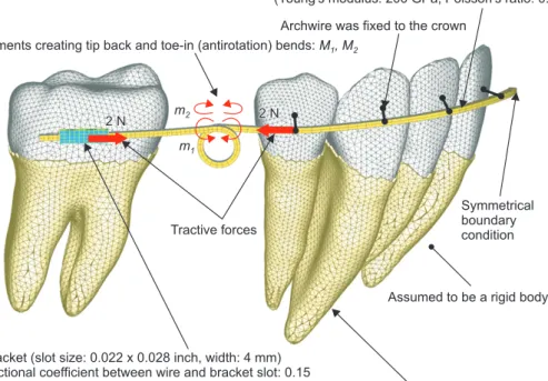
Figure 1. Finite element model for simulating ortho- dontic tooth movement.
0.018 x 0.025 inch stainless steel wire
(Young's modulus: 200 GPa, Poisson's ratio: 0.3) Archwire was fixed to the crown
Moments creating tip back and toe-in (antirotation) bends: M , M
1 2Tractive forces
Bracket (slot size: 0.022 x 0.028 inch, width: 4 mm) Frictional coefficient between wire and bracket slot: 0.15
Symmetrical boundary condition
Assumed to be a rigid body
Periodontal ligament (thickness: 0.2 mm, Young's modulus: 0.13 MPa, Poisson's ratio: 0.45)
2 N2 N
m1
2 N m2
2 N
MATERIALS AND METHODS
Finite element simulation
Figure 1 shows the finite element model for simula- ting orthodontic movement. Assuming symmetry for both sides of the arch, a model of only the right side was constructed. Three-dimensional models of the tooth were constructed on the basis of computed tomography images of a dental study model (i21D-400C; Nissin Dental Products, Kyoto, Japan).
12Each tooth was meshed with shell elements and defined as a rigid body.
The teeth and alveolar bone were assumed to be rigid bodies. The periodontal ligament (PDL) was assumed to be a linear elastic film with a uniform thickness of 0.2 mm, with Young’s modulus and Poisson’s ratio of 0.13 MPa and 0.45, respectively.
13In order to reduce the number of nodes, each tooth supported by the PDL was replaced with a so-called substructure element. This element had two nodes in which one node corresponded to the tooth and the other node to the alveolar socket.
An archwire was made from 0.018 × 0.025-inch stainless steel wire with Young’s modulus and Poisson’s ratio were E = 200 GPa and v = 0.3, respectively.
14The diameter of the helical loop was 3 mm, which was a standard configuration used in clinical treatment.
9The loop was incorporated at a distance of 10.5 mm from the molar bracket and was closer to the premolar bracket than the molar bracket. The off-center position of the loop was selected so that the molar bracket would not strike against the loop during space closure.
As the molar bracket moved along the archwire, the relative position of the molar and loop, as well as the force system, changed. All of these changes could be included in the finite element simulation. The wire was meshed with elastic solid elements. To reproduce the tip-back and toe-in (antirotation) bends, two bending moments of equal magnitude but in opposite directions, m
1and m
2, were applied to adjacent nodes at the top of the loop.
A bracket of 4-mm width and 0.022 × 0.028-inch slot was bonded on the first molar. The bracket was meshed with shell elements and defined as a rigid body.
The archwire slid along the bracket slot. The frictional coefficient was assumed to be m = 0.15, according to other experimental data.
15The archwire was fixed firmly to the anterior teeth at the bracket positions.
Symmetrical boundary conditions were applied at the median end of the archwire, and forces of 2 N were applied between the first premolar and first molar brackets.
Orthodontic movement was assumed to occur as a result of the initial movement induced by elastic deformation of the PDL.
13First, the initial movement was calculated by using the finite element model, and
then the alveolar socket of each tooth was moved by the same displacement and rotation as the initial movement.
By repeating this calculation, the teeth were moved in a step-by-step manner. The force system acting on the teeth was updated at each step. The movement pattern of the teeth changed as the teeth moved. The number of steps, N, corresponded to the time elapsed after force application.
The total number of nodes in the finite element model for simulating the orthodontic movement was 3,287.
For the finite element simulation, ANSYS 11 (ANSYS Inc., Canonsburg, PA, USA) was used.
Beam theory
Under translational movement, all forces acting on the molar are illustrated in Figure 2. When applying protractive force P (= 2 N), the archwire contacts the bracket at its edges. Normal contact forces, N
1and N
2, produce friction with a frictional coefficient of m = 0.15.
The net force F, which is the resistance to orthodontic movement, acts on the CR. The F is smaller than the protractive force P due to the friction. The distances of the CR from the brackets, L
1and L
2, could be determined using the finite element method.
Figure 2. Forces acting on the molar under translational movement.
Resistance to orthodontic movement
Center of resistance Protractive force
Cantilever beam
L2= 5.3 mm
Contact force
Frictional force Frictional coefficient
Translational movement of the molar
D= 3 mm Loop diameter
N2N2 N
N22
N2 P F
2
= 0.15
1
L1
= 7.3 mm
F
Contact force
P
N1
N1 N1 N1
C
= 11 mm
W= 4 mm
N1
Denoting by W the width of bracket, the equilibrium equations for the moments and forces were obtained as follows;
FL
1= N
1W, FL
2= N
2W, P = F + 2m (N
1+ N
2) (1) From these equations, the ratio of the net force F to protractive force P became
F = 1 (2)
P 1 + 2m (L
1+ L
2)/W
In this case, the moments L
1F and L
2F were applied to the archwire, and produced a tipping angle q
1and rotation angle q
2of the molar. Assuming the archwire to be a cantilever beam clamped at the premolar bracket, q
1and q
2could be easily calculated using Castigliano’s theorem.
16q
1= FL
1( C + πD) , EI
yq
2= FL EI
z2( C + πD 2 ) + FL GI
p2πD 2 (3) where D (= 3 mm) is the diameter of the loop, and C is the distance between the brackets. I
y, I
z, and I
pare the moments of inertia of the cross-sectional area of the archwire. Using the height w and width b of the archwire, I
yand I
zare expressed as
I
y= w 12
3b , I
z= wb 12
3(4)
Further, I
pbecomes
I
p= 0.181wb
3(5) for the rectangular section of w/b = 0.018 inch/0.025 inch = 1.4. For this archwire, the moments of inertia were calculated as I
y= 5.06 × 10
−3mm
4, I
z= 9.76 × 10
−3mm
4, and I
p= 21.2 × 10
−3mm
4. The shear modulus of elasticity G is obtained as G = E/2 (1 + v), where E is Young’s modulus and v is Poisson’s ratio. For the stainless steel archwire, G was 76.9 GPa.
RESULTS
Finite element simulation
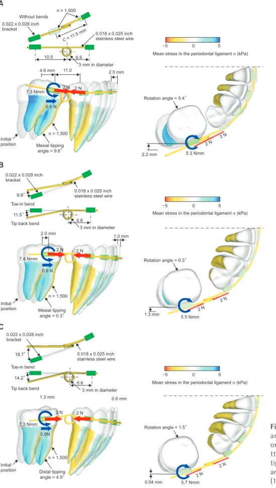
In the case of a running loop without bends, the teeth moved in the following way. Immediately after applying the force, the molar began to tip and rotate because moments acting on the molar were insufficient
to prevent these movements. As the tipping and rotation angles increased, elastic deflection of the archwire also increased, thereby increasing the moments. After the molars reached sufficient levels, they continued a translational movement while maintaining the initial tip and rotation. With this movement process, the extraction space was closed at iteration number N = 1,500. At this time, the molar moved mesially by 4.6 mm at the bracket position, tipped mesially by 9.6
o, and rotated counterclockwise by 5.4
oin the occlusal plane. The first premolar moved almost bodily, and the incisors tipped slightly lingually (Figure 3A).
When applying the moments m
1= 200 Nmm and m
2= 60 Nmm, the tip-back and toe-in angles increased to 11.5
oand 9.9
o, respectively. In this case, appropriate moments for preventing tipping and rotation were produced from the beginning. The molar moved bodily by almost 2.0 mm at the number of iterations N = 1,500.
The tipping and rotation angles were less than 1
o. The first premolar and incisors tipped slightly mesially (Figure 3B).
When applying the moments m
1= 320 Nmm and m
2= 50 Nmm, the tip-back and toe-in angles increased to 14.2
oand 18.7
o, respectively. In this case, excessive moments for bodily movement were produced from the beginning. After the molar tipped and rotated, it translated. At the number of iterations N = 1,500, the molar tipped distally by 4.9
oand rotated clockwise by 1.5
o. The anterior teeth tipped mesially, and the incisors intruded (Figure 3C).
The tip-back and toe-in angles for achieving bodily movement were about 12
oand 10
o, respectively. When increasing the tip-back angle from 0
oto 14.2
o, the movement pattern of the molar changed from mesial tipping to distal tipping. This led to a decrease in the movement distance of the molar at the bracket position.
Friction was produced between the archwire and the bracket, and hence, the net forces acting on the molar became smaller than the protractive force P (= 2 N).
When the bending angles of the running loop were increased, the moments acting on the molar increased in the early rotation and tipping movement. In this stage, the frictional force increased and the net force decreased. In the following translational movement, the moments were maintained at levels required for bodily movement; these were fixed values. At this stage, the frictional forces were kept constant and the net forces became 0.8 N irrespective of the bending angles.
Beam theory
For the first molar used in the finite element
simulation, distances of the CR from the bracket were
determined as L
1= 5.3 mm and L
2= 7.3 mm. In Figure
3A, the distance between the molar and premolar
Figure 3. Effect of bending angles of the running loop on the tooth movement pa- ttern. A, Without bends; B, tip-back angle (11.5
o), toe-in angle (9.9
o); C, tip-back angle (14.2
o), toe-in angle (18.7
o).
A
B
C
0.022 x 0.028 inch bracket
Without bends
10.5 6.6
4.6 mm 11.0
3 mm in diameter 2.0 mm n = 1,500
C =11.5 mm
0.018 x 0.025 inch stainless steel wire
7.3 Nmm
0.9 N 2 N 2 N
Initial
position Mesial tipping angle = 9.6
n = 1,500
Rotation angle = 5.4
2.2 mm 5.3 Nmm
2 N 2 N Mean stress in the periodontal ligament (kPa)
5 0 5
0.022 x 0.028 inch bracket
9.9
11.5 Toe-in bend
Tip back bend
0.018 x 0.025 inch stainless steel wire
1.0 mm 2.0 mm
2 N 2 N
3 mm in diameter 6.6
7.4 Nmm 0.9 N
Initial
position Mesial tipping angle = 0.3
n = 1,500
Mean stress in the periodontal ligament (kPa)
5 0 5
Rotation angle = 0.3
1.3 mm
5.5 Nmm 2 N
2 N
0.022 x 0.028 inch bracket
18.7
14.2 Toe-in bend
Tip back bend
0.018 x 0.025 inch stainless steel wire
3 mm in diameter 6.6
0.6 mm
2 N 2 N 7.3 Nmm
0.9N 1.3 mm
Initial
position Distal tipping angle = 4.9
n = 1,500
Mean stress in the periodontal ligament (kPa)
5 0 5
Rotation angle = 1.5
0.04 mm 5.7 Nmm
2 N 2 N