*교신저자 : 조재웅([email protected])
Tel: +82-41-521-9271 email: [email protected]
2014년 4월 20일, 수정일 2014년 5월 21일, 게재확정일 : 2014년 5월 25일
강민제1, 조재웅2*
1제주대학교 전자공학과, 2*공주대학교 기계자동차공학부
A Study on Structural Durability due to the Configuration of Ripper at Excavator
Min-Jae Kang1, Jae-Ung Cho2*
1Department of Electronic Engineering, Jeju University
2*Division of Mechanical & Automotive Engineering, Kongju University
요 약 본 연구에서는 굴착기에서의 리퍼의 형상에 따른 구조 및 진동, 피로해석을 하였다. 2가지의 모델들 모두, 작업장치의 바디와 이어지는 축에서 최대 응력이 발생하였고 최대 변형량은 직접작업부에서 발생하였다. Model 1 이 Model 2 보다 내구성면에서 구조적으로 더 안정적이라고 사료된다. 불규칙 피로 하중들 중에서는 하중의 변화가 극심한 ’SAE bracket history'의 경우가 대체적으로 가장 불안정한 경향을 보이고 있고, 비교적 하중의 변화가 완 만한 'Sample history'의 경우가 가장 안정함을 보이고 있다. 본 연구의 결과를 종합하여 굴착기에서의 리퍼의 설 계에 응용한다면, 그 파손 방지 및 내구성을 검토하여 그 설계에 유용하게 활용될 것으로 사료된다.
주제어 : 굴착기 리퍼, 최대 응력, 최대 변형, 피로수명, 피로손상, 내구성
Abstract In this study, two models due to the configuration of ripper at excavator are investigated by structural and fatigue analyses. The maximum stress and deformation are happened at the axis connected with the body of working device and the direct working part respectively. Model 1 is thought to have more structural durability than model 2. Fatigue life or damage in case of 'SAE bracket history' whose load change is most severest among non-uniform fatigue loads is shown to become most unstable.
But life or damage in case of 'Sample history' whose load change is slowest among non-uniform fatigue loads is shown to become most stable. These study results can be effectively utilized with the design of ripper at excavator by anticipating and investigating prevention and durability against its fatigue damage.
• Key Words : Excavator ripper, Maximum stress, Maximum deformation, Fatigue life, Fatigue damage, Durability
1. 서론
오래전부터 인간은 환경을 개발하고, 이용하는 데 있 어서 보다 편리한 도구를 사용하기 위해 필요한 기계장 비를 만들어왔다. 이러한 도구들은 그 시대의 자재와 인
간의 지혜를 바탕으로 발명되고 고안되어 이용되어졌으 며, 계속하여 문제점을 보안하고 개선되어 더욱 더 발전 해오고 있다. 이처럼 오래전부터 인간은 필요에 의해 많 은 건설기계들을 개발하고 사용해 오면서 다양한 문제점 을 발견하게 되면서 피로파손에 대한 연구가 매우 중요
으로 큰 힘을 얻어 사용됨으로서 각 부품에 피로파손에 대한 부품 수명이 중요하다 할 수 있다. 그리고 굴착기의 구조 및 기능에 대하여 살펴보면, 상부회전체, 하부주행 체, 프론트 어태치먼트(작업 장치)로 구성되어 있다. 굴 착기는 땅을 팔 때 철근은 1회만 굽히면 부러지지 않지만 몇 번의 굽힘을 반복하게 되면 재질이 견고하고, 동시에 약해지게 된다. 이와 같이 반복되는 부하에 의한 재질의 변화를 피로(Fatigue)라고 한다. 그리고 어느 한도 이상 까지 피로가 진행되게 되면 재료는 파괴된다. 이를 피로 파괴(Fatigue Fracture)라고 하며, 항복점 이하의 응력에 서도 피로가 반복되면 변형이 축적되어 시간에 지남에 따라 재료의 변형이 일어난다. 또한 굴착기의 프론트 어 태치먼트(작업 장치)중에서 리퍼는 그 쓰임이 다양하다.
본 연구에서는 리퍼의 형상에 대하여 피로수명을 평가하 고자 하였다.[6-8]
2. 연구 모델 및 물성치
[Fig. 1] Mesh shape of model 1
[Fig. 2] Mesh shape of model 2
본 연구에서는 리퍼를 모델로 삼고 프레임에 힘을 주 었을 때 나타나는 변형량과 응력을 구한다. 모델의 형상 은 실제 리퍼 프레임의 모양을 참조하여 CATIA를 이용 하여 모델링 한 후 ANSYS를 이용하여 해석하였다. 각 모델에 대한 메시 모양은 Fig. 1과 Fig. 2에 나타났다. 또 한 Model 1과 Model 2의 절점과 요소는 Table 1에 나타 났다. 또한 리퍼는 구조용 강으로 구성되어 있으며, 그 물 성치는 Table 2에 나타나 있다.
[Table 1] Nodes and elements at models
Model Nodes Elements
Model 1 6998 3317
Model 2 3088 1488
[Table 2] Material property
Young's Modulus(GPa) 200
Poisson's Ratio 0.3
Density(kg/mm) 7.85× Tensile Yield Strength(MPa) 250 Compressive Yield Strength(MPa) 250 Tensile Ultimate Strength(MPa) 460 Compressive Ultimate Strength(MPa) 0
3. 해석 결과
3.1 해석 조건본 연구에서는 실제와 똑같은 조건으로 해석에서 실 현하였다. Model 1과 Model 2의 경계조건은 각각 Fig. 3 과 Fig. 4 같다. Fig. 3과 Fig. 4에 보면 리퍼의 위 면을 고정시키고 리퍼의 실제 작업기둥에 3000N인 힘을 가해 주었다.
[Fig. 3] Boundary Condition of Model 1
[Fig. 4] Boundary Condition of Model 2
3.2 구조해석의 결과
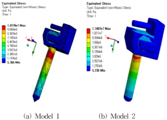
Fig. 3과 Fig. 4에 나온 경계조건으로서 정적인 구조해 석을 하였다. Fig. 5에 Model 1과 Model 2의 등가응력을 나오며, Model 1의 최대 등가응력은 1.0778×10⁷Pa로 나 타나고 Model 2의 최대 등가응력은 1.1487×10⁷Pa로 나타 났다. 또한 2가지 모델들 모두, 작업장치의 바디와 이어 지는 축에서 최대 응력이 발생하였다. Fig. 6에 Model 1 과 Model 2의 전변형량이 나오며, Model 1의 최대 변형 량은 4.1459×10⁻⁶m로 나타나고 Model 2의 최대 등가응력 은 2.742e×10-6m로 나타났다. 또한 2가지 모델들 모두 직 접작업부에서 최대 변형량을 발생하였다. 따라서 Model 1및 2에서 최대 변형량이 적게 발생하여 그 값이 미미하 지만 Model 1에서의 응력이 Model 2 보다 비교적 적게 발생하여 Model 1이 내구성면에서 더 안정적이라고 사 료된다.
(a) Model 1 (b) Model 2 [Fig. 5] Equivalent stress at structural analysis
(a) Model 1 (b) Model 2 [Fig. 6] Total deformation at structural analysis
3.2 피로해석의 결과
모델의 경계 조건은 역시 Fig. 3 및 Fig. 4와 같으며, 리퍼의 Model 1 및 Model 2가 받는 피로하중에 의한 피 로수명과 파손에 대해서 해석하였다. Fig. 7에서와 같이 불규칙 피로 하중의 내역들로서 ‘SAE bracket history’,
‘SAE transmission’ 및 ‘Sample history’을 사용하였다.
경과 사이클들에 대한 응력 진폭과 일정한 평균 응력의 내역을 나타낸다.
(a) SAE bracket history
(C) Sample history [Fig. 7] Fatigue loading history
(a) Model 1 (b) Model 2 (1) SAE bracket history of models 1 and 2
(a) Model 1 (b)Model 2 (2) SAE transmission of models 1 and 2
(a) Model 1 (b) Model 2 (3) Sample history of models 1 and 2
[Fig. 8] Fatigue life of ripper
두 모델 모두 다 같은 피로 하중을 받고 있고 ‘SAE bracket history', 'SAE transmission' 및 ’Sample history'를 받는 경우들에서의 사용 가능한 피로 수명의 등고선들을 Fig.8에서와 같이 나타내었다. 두 모델 다 같 은 양상을 나타내고 있고, 그림들에서 볼 수 있듯이 하중 의 변화가 극심한 ‘'SAE bracket history’'가 그 최대 수 명이 3.3693×10⁵Cycle로 그 수명이 가장 작음을 알 수 있 고 하중의 변화가 완만한 ‘Sample history'의 경우가 그 수명이 2×10⁷Cycle정도로 가장 긴 것을 알 수 있었다. 두 모델 공히, ‘Sample history'의 경우는 피로 수명은 ‘SAE bracket history'의 경우보다 약 60배 정도 수명이 길고
’SAE transmission'의 경우는 ‘SAE bracket history'의 경우보다 3.5배 정도 수명이 길어짐을 알 수 있었다.
(a) Model 1 (b) Model 2 (1) SAE bracket history of models 1 and 2
(a) Model 1 (b) Model 2 (2) SAE transmission of models 1 and 2
(a) Model 1 (b) Model 2 (3) Sample history of models 1 and 2
[Fig. 9] Fatigue damage of ripper
Fig. 9에서 볼 수 있는 바와 같이, 등고선으로 된 피 로 손상은 설계 수명을 사용 가능 수명으로 나눈 것이다.
피로 손상이 아주 적은 상태의 부분으로서, 3가지 경우들 의 공히 비교할 수 있다. Fig. 9에서 보면 두 모델 모두 하중의 변화가 극심한 'SAE bracket history'에서 손상 이 2968로 가장 많은 것을 볼 수가 있고 하중의 변화가 완만한 ‘Sample history'의 경우는 그 손상이 50정도로 가장 적은 것을 알 수 있었다. 따라서 불규칙 피로 하중 들 중에서는 하중의 변화가 극심한 ’SAE bracket history'의 경우가 대체적으로 가장 불안정한 경향을 보 이고 있고, 비교적 하중의 변화가 완만한 'Sample history'의 경우가 가장 안정함을 보이고 있다.
4. 결론
본 연구에서는 굴착기에서의 리퍼의 형상에 따른 구조
및 피로해석을 통하여 다음과 같은 해석 결과를 보였다.
1. 길이 100mm에 날카로운 작업부와 길이 70mm에 라운드된 작업부를 모델링한 2가지 모델들 모두, 작업장치의 바디와 이어지는 축에서 최대 응력이 발생하였고 최대 변형량은 직접작업부에서 발생하 였다.
2. 최대변형량은 Model 1에서 4.1459×10⁻⁶m, Model 2 에서 2.7424×10⁻⁶m로 Model 2에서 작게 발생하였 고, 최대 응력은 Model 1에서 1.0778×10⁷pa, Model 2에서 1.1487×10⁷pa로 Model 2에서 크게 발생되었 다. 따라서 Model 1및 2에서 최대 변형량이 적게 발생하여 그 값이 미미하지만 Model 1에서의 응력 이 Model 2 보다 비교적 적게 발생하여 Model 1이 내구성면에서 더 안정적이라고 사료된다.
3. 두 모델 모두 하중의 변화가 극심한 'SAE bracket history'에서 손상이 2968로 가장 많은 것을 볼 수 가 있고 하중의 변화가 완만한 ‘Sample history'의 경우는 그 손상이 50정도로 가장 적은 것을 알 수 있었다. 따라서 불규칙 피로 하중들 중에서는 하중 의 변화가 극심한 ’SAE bracket history'의 경우가 대체적으로 가장 불안정한 경향을 보이고 있고, 비 교적 하중의 변화가 완만한 'Sample history'의 경 우가 가장 안정함을 보이고 있다.
4. 본 연구의 결과를 종합하여 굴착기에서의 리퍼 의 설계에 응용한다면, 그 파손 방지 및 내구성을 검토하여 그 설계에 유용하게 활용될 것으로 사료 된다.
REFERENCES
[1] Kim, S. K., and Ock, J. H., “A Platform Moving Model for an Intelligent Excavator,”The Korean Society of Civil Engineers, Vol. 27, No. 6D, pp.
767-774, 2007.
[2] Moon, D. H., Cho, H. I., and Baek, S. G., “A Case Study of the Design of Robot Welding Station in an Excavator Factory Using 3D Simulation,” The Korea Society for Simulation, Vol. 15, No. 1, pp.
51~58, 2006.
[5] Seo, J. M., and Kim, S. K., “The Study on Measures for Reducing Safety Accidents of Excavator,” The Korea Institute of Building Construction, Vol. 8, No.
3, pp. 3-144, 2008.
[6] Lim, T. H., and Yang, S. Y., “Development and Application of Simulator for Hydraulic Excavator,”Journal of the Korean Society for Precision Engineering, Vol. 23, No. 9 pp. 142-148, 2006.
[8] Kang, S. S., and Cho, S. K., 2010, “Structural Design and Analysis for the Reinforced Frame of Vehicle,”Journal of the Korean Society of Machine Tool Engineers, Vol. 19, No. 4, pp. 504-510.
[8] Y. S. Joo, Y. K. Kim, B. W. Kim, J. O. Moon and K. S. Lee, “Structural Analysis of a Large Automobile Frames,” Fall Conference Proceedings, KSAE, Vol.2, pp. 1417-1422, 2003.
저자소개
강 민 제(Min-Jae Kang)
․Feb. 1982: Seoul National University, B. S. in Electrical Engineering
․May. 1989 :Louisvill University, M. S. in Electrical Engineering
․Aug. 1991: Louisvill University, Ph. D in Electrical Engineering
․1992 ~ Present : Professor, Electronic Engineering, Jeju National University
<Field of Specialization> :
․Aug. 1986: Inha University, , Ph.
D in Mechanical Engineering
․1988 ~ Present : Professor, Div. of Mechanical &
Automotive Engineering, Kongju National University
<Field of Specialization> :
Fracture Mechanics(Dynamic Impact) Impact Fracture of Composite Material) Fatigue and Strength Evaluation Durability and Optimum Design
Design & Analysis of Machine & Automobile