DOI http://dx.doi.org/10.7467/KSAE.2016.24.4.487
Development of New-type Weight Classification System
Byunghyuk Park
*1)․Jaeho Hwang
2)․Jaeyoung Choi
3)1)Safety Electronics Engineering Team, Hyundai Mobis, 17-2 Mabuk-ro, 240beon-gil, Giheung-gu, Yongin-si, Gyeonggi 16891, Korea
2)Active Safety Control Engineering Team, Hyundai Mobis,17-2 Mabuk-ro, 240beon-gil, Giheung-gu, Yongin-si, Gyeonggi 16891, Korea
3)Mechatronics Test & Development Team, Hyundai Mobis, 17-2 Mabuk-ro, 240beon-gil, Giheung-gu, Yongin-si, Gyeonggi 16891, Korea
(Received 27 April 2016 / Revised 17 May 2016 / Accepted 30 May 2016)
Abstract : In order to comply with the Federal Motor Vehicle Safety Standard(FMVSS) No. 208 that has been in force since September 2003, an automatic airbag suppression system has become an essential option for detecting and protecting infants and children seated in the front passenger seat of vehicles in the U.S. market. MOBIS has developed the world’s first weight-based OCS under the name NWCS. NWCS is composed of two sensors and ECU. It is sub-packaged in order to minimize the seat structure deviation. In this paper, technical features, robustness and performance of NWCS are summarized and discussed.
Key words : Occupant classification system, Weight classification system, Weight sensor, FMVSS208
1. Introduction
1)After passive restraint system such as airbags was introduced to automotive vehicles, many people have been saved during the severe crash accident. However, as the number of vehicles installed with airbags was increased and the rate of occupants being seriously injured or killed due to inappropriate airbag deploy- ment became a critical subject to be resolved.
In response to this problem caused by airbags, the United States DOT(Department of Transportation) revised the safety regulations(FMVSS208).
1)In order to comply with the revised regulation which is manda- tory 100 % since Sept. 1st, 2005, vehicle manufacturers had to adopt several technologies especially for the front passenger occupant protection resulted in so-called Advanced Airbag system. Especially in order to protect
*A part of this paper was presented at the KSAE 2016 Spring Conference
*Corresponding author, E-mail: [email protected]
the infants and children that sit in the front passenger seat, a system that can discriminate child and adult had to be introduced. OCS has been developed for this purpose and plays a key role in the Advanced Airbag system.
2)However, discrimination requirement between adult and 6 year old child for the early full-suppression systems have been resulted in critical field problems especially with the discrimination capability of small- size adult and resulted in high cost to increase the system resolution. In order to solve these problems, MOBIS developed and introduced an innovative weight based system named NWCS as an optimization of performance & cost for the semi-suppression option i.e.
1YO(1 year old) detection system. NWCS is composed
of 2 sensors and ECU and is sub-packaged in order to
minimize the seat structure deviation. The system is
world first concept, thus every aspect of technical
requirement has been reviewed during the develop-
ment. In this paper, technical features, robustness and
performance of NWCS are summarized and discussed.
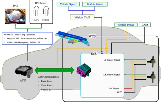
Fig. 1 Schematics of NWCS and vehicle interface
2. Development of NWCS
In this chapter, the specification, system structure and performance of NWCS which MOBIS developed for compliance with the semi-LRD airbag requirements are provided and discussed.
2.1 NWCS System Interface Outline
NWCS currently available in the market is utilizing 2 sensors as shown in Fig. 1. NWCS is interfaced with ACU continuously performing general diagnostic, weight measuring and classification. Sensor location mounted on a seat frame is the most important parameter to be considered during the early development phase.
7)For establishing the optimal sensor location, we adopted the DFSS procedure as standard development process. Diagonal & LH locations are suitable for the target operation of NWCS and LH location is more robust than the other case as shown in Fig. 2. For the detail on the process of DFSS, refer to Kim et. al.
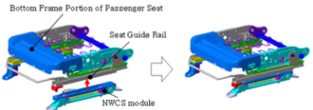
3)2.2 NWCS integration - Front Passenger Seat The passenger seat can be usually divided into a
Fig. 2 Weight sensor positions of NWCS
waist supporting portion for supporting the waist and back regions of a seated passenger and a bottom portion for sustaining the load of the passenger. In most of the cars being produced recently, the passenger seat is disposed so as to be movable in a back-and-forth direc- tion by a user so that passengers with different body sizes can be comfortably seated on the passenger seat in the most comfortable posture.
Although deviations exist according to the angle of
the waist supporting portion or the seated posture of the
passenger, most of the weight of the passenger is
supported by the bottom portion, and thus NWCS for
classifying whether a passenger is seated and the type
of the passenger is installed below LH side(Inner
position in vehicle) of the seat guide rails in the bottom
portion of the front passenger seat by fastening the
respective mounting bolts as shown in Fig. 3.
Fig. 3 Installation of NWCS in the passenger seat frame
2.3 Design Description of NWCS
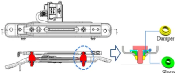
2.3.1 Basic StructureNWCS includes a lower bracket fixed to the inside bottom of the vehicle and an upper bracket disposed above the lower bracket as shown in Fig. 4 and Fig. 5.
Fig. 4 Constituent components of NWCS
Fig. 5 Sectional view of NWCS installed in the vehicle
2.3.2 Strain Measurement Principle
The resistor element arranged in the strain generator is wound around the outer circumferential surface of the strain generator. When a load acts on the passenger seat, this loads acts on the bolt portions such that a load acting direction is a direction perpendicular to the axial direction of the strain generator. Thus, the strain generator is strained due to a shear force or a bending moment generated in the strain generator. Since the resistance of the resistor element varies as the strain generator is strained, the load can be measured by
processing this resistance variation in the signal proce- ssing circuit. The correlation between the applied strain ε and the relative changed of the resistance of resistor element is described by the equation.
4)
(1) The factor k, also known as the gauge factor, is a cha- racteristic of resistor element and the exact value is speci- fied on each strain gauge package.
5)The change in resis- tance corresponding to typical values of strain in prac- tical applications is usually only a fraction of an ohm.
In order to measure small changes in resistance accu- rately, four resistor elements R
1to R
4with an excitation voltage, V
EX, that is applied across the bridge are linked together according to the Wheatstone bridge circuit as shown in Fig. 6. Where R
1, R
2, R
3, and R
4are the electrical resistance glued at different locations on the circumferential surface of the strain generator, and are connected so that two opposite branches of a Wheatstone bridge strain R
1and R
4have the same sign between themselves and opposite sign to the other two branches, R
2and R
3, causing an imbalance.
Fig. 6 Wheatstone bridge circuit
The output voltage of the bridge, V
O, is equal to the following relationship.
V
EXV
O≅
R
R
R
R
R
R
R
R
(2)
From this equation, it is apparent that when no force
is applied, the output voltage V
Owill be zero. The
Wheatstone bridge circuit assumes an initially balanced
bridge and the bridge balancing condition is R
1R
3=
R
2R
4.
In practice, however, resistance tolerances and strain induced by resister element application can generate some initial offset voltage. This initial offset voltage is handled through adjusting the resistance in the bridge to rebalance the bridge to zero output voltage. Any change in resistance of resistor element will produce a nonzero output voltage. Therefore, when a force is applied to a direction perpendicular to an axial direction of the strain generator via the bolt portions, two opposite arms of Wheatstone bridge strain R
1and R
4have positive sign(tensile surface stress) between themselves and opposite sign (compressive surface stress) to the other two arms, R
2and R
3, causing imbalance, thus provi- ding the output voltage as shown in Fig. 7.
Fig. 7 Force conversion principle of NWCS
2.3.3 Structural Characteristics (A) Anti-Shock Damper
As shown in Fig. 8, the anti-shock damper serves to measure the load being transferred when the load transferred from the passenger is transferred to the weight sensors through the upper bracket and then absorb and dissipate the load which is transferred to the lower bracket disposed below the weight sensors. In this manner, the anti-shock damper prevents the over- load sensors from receiving an excessive load and being damaged by absorbing and dissipating the load transferred to the lower bracket. Furthermore, the anti- shock damper performs the function of compensating for an assembly tolerance generated in the assembling and fastening of the weight sensors, as well as the function of preventing damage to the weight sensors.
Fig. 8 Sectional view of weight sensor mounting part
In the case where a predetermined assembly tolerance is generated between the weight sensors to be assembled and the lower bracket and the upper bracket of NWCS, the assembly tolerance can be compensated for by disposing the anti-shock damper having a size corres- ponding to the assembly tolerance between the weight sensors and the upper bracket.
The anti-shock damper is formed in a ring shape.
Further, the anti-shock damper is preferably made of rubber which can absorb the predetermined load trans- ferred to the lower bracket from the weight sensors.
The anti-shock damper of this type is advantageous in that the existing construction can be used as it is without any particular change in shape because it is fit to the upper and lower projecting ends of the weight sensors having the same shape as the existing ones.
(B) Over-Load Prevention Structure
We enhanced the crash performance of NWCS by utilizing the over-travel prevention structure in order to minimize an excessive load transferred to the passenger seat due to the low speed crash. NWCS is constructed of a stopper bolt for fastening through both of the lower bracket and the upper bracket in a horizontal direction from one side as shown in Fig. 9. The stopper bolt pre- vents damage to the weight sensors by limiting the deformation of the seat structures, especially the parts adjacent to the weight sensor. For the detail on over- travel stop mechanism, refer to Hwang et. al.
6)2.4 Performance Description of NWCS
In this chapter, performance and robustness of NWCS
in the various ambient conditions are provided and
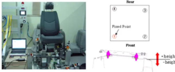
Fig. 10 Setup picture for lateral load test
Fig. 11 Offset variation with respect to lateral load Fig. 9 Over-travel prevention structure in NWCS
discussed. During our investigation, the allowed accu- racy tolerance is set to ±6 kg. Excessive weight offset more than the system accuracy target (±6 kg) could give inconsistent classification performance of NWCS due to losing its weight measuring accuracy.
2.4.1 Lateral Load Performance
In order to evaluate the stability of NWCS against
the inordinate lateral load, we checked the weight-
offset (kg) after applying lateral load (40 kgf, 70 kgf)
respectively to the passenger seat for 10 seconds in
various directions as shown in Fig. 10. The weight-
offset variation from the applied the load for all seat
positions is depicted in Fig. 11. After performing the
test, there were not any parts of the seat damaged, and
the measured the weight-offset did not deviate more
than ±4 kg at all conditions.
Fig. 12 Method of investigating seat MPV influence 2.4.2 Mounting Point Variation Performance
In order to investigate the influence on system per- formance caused by the variation in mounting of the seat with NWCS in vehicle, we conducted a perform- ance test as shown in Fig. 12. With one mounting point of the seat being fixed, other 3 mounting points were moved in the height direction of the seat. The height (H) of other 3 mounting points is adjusted by changing from 0 mm to 5 mm. In this condition, the apparent weight, which was generated by tolerance of between seat and vehicle, was measured. The result of this test is presented Fig. 13. The measured weight-offset (kg) did not deviate more than ±4 kg from the applied the weight (0 kg, 20 kg, 40 kg) for all seat track positions and all conditions of mounting point variation.
2.4.3 Temperature Performance
Fig. 14 shows the system performance of NWCS while exposing to temperature cycling from -40 °C to +85 °C for specified thermal cycles to simulate accele- rated test condition for drastic change in ambient tem- perature experienced during the vehicle’s service life.
Temperature cycle, which is applied in order to verify the system robustness respect to the temperature, is depicted in Fig. 15.
2.4.4 Crash Performance
In order to verify the crash effect to system, the low
Fig. 13 Weight deviation with respect to Seat MPV
Fig. 14 Temperature test result
Fig. 15 Temperature cycle
Fig. 18 Classification performance features of NWCS Fig. 16 Setup picture for low speed crash test
Table 1 Low speed crash test results
Test
Test condition Test result Dummy
(kg)
G Level (g)
Weigh-offset (kg) Result
Frontal 5 MPH 90.3 5.25 -0.7 OK
Frontal 8 MPH 90.3 7.08 -1.1 OK
Frontal 5 MPH 90.3 5.3 0.7 OK
Frontal 8 MPH 90.3 7.12 -2.2 OK
Rear 5 MPH 90.3 5.23 0.2 OK
Rear 8 MPH 90.3 7.3 2.5 OK
Rear 5 MPH 90.3 5.25 2.5 OK
Rear 8 MPH 90.3 7.27 3.1 OK
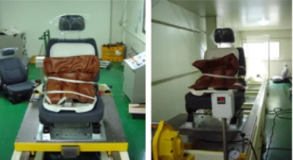
speed crash test is conducted as shown in Fig. 16. The result of this test is presented Table 1.
After clash (5 mph, 8 mph) of the passenger seat with the weight corresponding that 95 % dummy in forward and rear direction respectively, there were not
any parts of the seat damaged, and the weight-offset was measured to be maximum 3.1 kg at the 8 mph rear crash condition. Through these tests, we confirm that the crash performance of NWCS is high enough and it gives the consistent weight classification performance in the crash conditions which is lower than 8 mph crash speed.
2.4.5 Classification Performance
The classification performance of NWCS is verified by the test including NHTSA FMVSS208 and Due- care. For each occupant (the 5 % female adult and CRS with 1YO child) seated as seen in Fig. 17, the measure- ments were performed about each test conditions. The test results are presented Fig. 18. As is easily seen from this figure, the range between a minimum weighting 5 % female and a maximum weighting CRS with 1YO child are distinguished with sufficient detection margin.
Fig. 17 Simple view of classification performance test