Vol.34, No.2 pp. 111~115, 2010 (ISSN-1598-5725)
A Study on Absorption Properties of the EM Wave Absorber Using TiO
2in W-band
Chang-Mook Choi†․Kwang-Soob Ko*
*,†Department of Navigation & Shiphandling, Korea Naval Academy, Jinhae 645-797, Korea
Abstract : In this paper, the electromagnetic (EM) wave absorbers using TiO2 as a dielectric material with chlorinated polyethylene (CPE) were investigated in W-band radio frequencies. We compared the relative permittivity with reflectionless curve and the absorption properties of samples containing 40 wt.%, 50 wt.%, 60 wt.%, 70 wt.%, and 80 wt.% TiO2. It is possible to realize a complex relative permittivity satisfying the reflectionless condition by choosing composition ratio of TiO2. The optimized composition ratio of TiO2 for the maximum absorption property is about 70 wt.%. As a result, we have confirmed the realization of an EM wave absorber with a high absorption property in W-band radio frequencies.
Key words : Absorption property, Complex relative permittivity, Material property, Reflectionless condition, TiO2..
†Corresponding Author : Chang-Mook Choi, [email protected], 010-4846-1864
* [email protected], 055)542-0565
1. Introduction
Millimeter waves offer a solution to the increasing demand for frequency allocation due to low-frequency band saturation and the requirement for higher data rates.
Moreover, a high directivity can be obtained by the small antennas which are associated with small-sized circuits. For these reasons, the extensive research on the applications of millimeter waves has been done. In particular, research on applications in W-band is progressing rapidly (Russell., 1997;
Brooker, 2005). The electromagnetic (EM) wave absorbers are effective for prevention of electromagnetic interference possibly caused by high degree of usage of electromagnetic waves. Therefore, researchers have confirmed the realization of a sheet-type absorber with a high absorption property at these frequency ranges (Soh and Hashimoto, 2001).
As is well known, EM wave absorbers can be broadly divided into two types from the viewpoint of material. One is a wave absorber using a dielectric material and the other is a magnetic wave absorber using a ferrite material (Kotsuka and Yamazaki, 2000).
In general, Carbon and titanium dioxide as a dielectric material, and Permalloy as a magnetic material are useful materials for EM wave absorption in W-band, and absorption properties of EM wave absorbers using Carbon or Permalloy have been investigated (Choi, 2007; Kim, 2007).
But, absorption properties of samples in composition ratio of
TiO
2have not been reported yet.
In this research, we investigated EM wave absorbers using TiO
2as a dielectric material with chlorinated polyethylene (CPE) as a binder. First of all, we fabricated sheet-type EM wave absorbers containing 40 wt.%, 50 wt.%, 60 wt.%, 70 wt.%, and 80 wt.% TiO
2. These material properties were calculated using S-parameters and analyzed along with reflectionless condition. The optimized composition ratio of TiO
2as a dielectric material has been estimated for high absorption property under reflectionless condition. We have confirmed the realization of an EM wave absorber containing TiO
2in W-band.
2. Preparation and measurement of samples
2.1 Preparation of samples
In this research, we fabricated some samples in different composition ratio of TiO
2and CPE. TiO
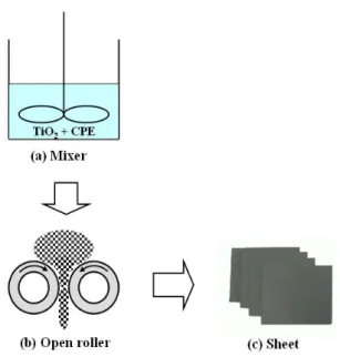
2was mixed with the binder of CPE, and a sheet-type absorber was fabricated by using an open roller as shown in Fig. 1. The open roller's surface temperature was maintained at 70 ˚C during sample preparation because the surface temperature affects the EM wave properties of sheet-type absorbers (Moon, 2003). To investigate the effect of the composition ratio of the material, we fabricated samples containing 40 wt.%, 50 wt.%, 60 wt.%, 70 wt.%, and 80wt.% TiO
2.
The dimensions of the sample to measure the complex
relative permittivity were 2.54 × 1.27 × 1.5 mm and 2.54 × 1.27 × 3 mm.
Fig. 1 Manufacturing process of an EM wave absorber
2.2 Measurement for reflection coefficient
The measurement equipment in this research is used for the reflection measurement. It includes an ANRITSU ME 78080A broadband vector network analyzer, rectangular waveguide, sample holder, and short circuit. Figures 2 and 3 are diagrams of the measurement setup used for measuring the reflection coefficient and the sample holder for rectangular waveguide, respectively. The reflection coefficient of the sample can be obtained from S
11after critical calibration.
3. Results and discussion
3.1 A comparison of the relative permittivity of the samples
The relative permittivity of the samples is calculated using S-parameters of a network analyzer by using ℓ-2ℓ method (Naito, 1987). Figure 4 shows plots of measured complex relative permittivity ( ε
r= ε
r'−
jε
r'') at different frequencies, together with the first-order, second-order and third-order curves among the reflectionless curves obtained by solving eq.(1)
1 2 )
tanh(
1 r =
r
j d