집기‐놓기 작업을 위한 이동 머니퓰레이터의 자세 선정
Pose Selection of a Mobile Manipulator for a Pick and Place Task
조 경 래1 Cho Kyoung‐Rae1
Abstract A mobile manipulator is a system with a robotic manipulator mounted on top of a mobile base. It has both indoor and outdoor applications for transporting or transferring materials. When a user gives commands, they are usually at high levels such as “move the object to the table,” or “tidy the room.” By intelligently decomposing these complex commands into several subtasks, the mobile manipulator can perform the tasks with a greater efficiency. One of the crucial subtasks for these commands is the pick‐and‐place task. For the mobile manipulator, selection of a good base position and orientation is essential to accomplishing this task. This paper presents an algorithm that determines one of the position and orientation of a mobile manipulator in order to complete the pick‐
and‐place task without human intervention. Its effectiveness are shown for a mobile manipulator with 9 degrees‐of‐freedom in simulations
Keywords: mobile manipulator, pick‐and‐place, pose selection, grasp planning
1. Introduction1)
Traditionally, robots have been developed for industrial applications, but recently they are being developed for a variety of service applications such as medical robotics, hazardous material handling, and home
‐service robots. Unlike industrial robots, these robots operate in home environments that constantly change, and perform various tasks to assist humans. They are typically designed with a mobile manipulator for which a manipulator is mounted on a mobile base. This provides the mobility and object‐handling capability necessary for service robots.
Service robots often perform catch‐and‐ferry operations wherein they grasp and move common objects like cups and bottles. They also perform pick‐and‐place (PNP) operations wherein more intelligence is required to place an object in a particular pose, i.e., position and orientation,
Received : Oct. 26. 2011; Reviewed : Nov. 01. 2011; Accepted : Nov. 14. 2011
1 동서울대학교 항공자동차기계공학부
that is consistent with the current context. When tidying up a room, for example, PNP operations are needed many times to place objects in appropriate poses.
A PNP operation consists of moving mobile base of the robot near an object, and then grasping the object using manipulator of the robot. If the target placement location is within the current
work volume, then the manipulator places the object while the mobile base remains fixed. Otherwise, the mobile base has to move near the target location before object placement. In order to reliably and efficiently perform the PNP operation, the robot requires an integrated algorithm that combines navigation, object recognition, grasp pose determination, visual servoing while the object is being grasped, another possible navigation, and object placement.
So far, the research on mobile manipulation has been concentrated on using redundant degrees of freedom (dof) resulting from the combination of the mobile base (3 dof) and the manipulator (5 or 6 dof) for smooth and
seamless execution of various tasks[1-4]. A system integration aspect of mobile manipulation was recently presented by L. Petersson[5], where the components of the PNP operation are rigorously treated to find optimal order of execution. T. Takahama presented motion planning and system integration algorithms for a mobile robot with dual manipulators for the specific task of arranging books in a bookcase[6].
R. David presents a method to inverse kinematics for mobile manipulator grasp pose selection which integrates obstacle avoidance and joint limit checking into the pose selection process.[7] However this paper does not propose the optimal solution to solve the PNP problem, which has a few of pick‐and‐place tasks.
Thus, almost papers assume that the pose of the mobile base is given, and thus do not provide a solution to a PNP problem on mobile manipulation in general, changing environments. In my previous works[8], the solution of the position of robot base in the process of PNP tasks was proposed. In this paper, the solution of the pose of robot base is proposed.
Our paper presents an algorithm that determines the poses of a service robot’s mobile base that are required to perform PNP operations in a changing environment.
Section II presents a rigorous analysis of the PNP operation for a mobile manipulator, while Section III describes robot‐modeling and training‐data‐acquisition techniques for mobile manipulation. Presented next in Section IV is the pose determination algorithm for the mobile base during PNP operations. Simulation results and conclusions are then presented in Section V and VI, respectively. For the purpose of this paper, the term
“robot” refers to a mobile manipulator, “pose” refers to both the position and orientation of the mobile base or an object, and “configuration” of the manipulator refers to the set of joint angles that completely specifies the pose of each manipulator link.
2. Problem Description
The pick‐and‐place problem for a robot manipulator involves the kinematic constraints of the robotic arm,
grasp constraints for a stable grasp, collision avoidance between the gripper and other objects, and collision‐free motion for moving the robot base and arm. We use the term geometric constraints to refer to the restrictions related to the grasp geometry and collision avoidance between the robot and objects in its environment. First, we describe the PNP problem for a robot arm, and then describe the same problem for a mobile manipulator.
2.1 Pick‐and‐Place Task for Manipulator The procedure for a general PNP operation is a sequence of arm approach toward an object, grasp operation, transfer movement, place operation and retraction movement. In order to successfully execute each of these steps, there must be a solution for the inverse kinematics of the manipulator and a collision‐
free path for the manipulator. Even when these exist, there may be no feasible manipulator motion due to the geometric constraints of the grasp poses (there may still be collisions between the gripper and objects in the workspace). On the other hand, there may be a grasp pose that enables both pick and place operations, but there may not be an inverse kinematic solution or collision‐free motion to achieve the grasp pose. This shows the complexity of PNP operations, which have inter‐related constraints including kinematics, grasp planning, and collision‐free path planning[9]. The set of constraints affecting the grasping and thus PNP operations can be defined as follows.
Definition 1. Let Gpu(o) and Gpd(o)be the sets of grasp poses used to pick up and put down an object, o, respectively. These poses are defined with respected to the object’s reference frame. Further, let g, c, k, and m denote the satisfaction of grasp constraints (for stable grasp of the object), collision constraints (for avoiding collisions with robot hand and objects other than the one to be grasped), kinematic constraints (for satisfying inverse kinematics of the robot arm to place the hand at the grasp site) and collision‐free motion constraints (for moving the robot arm so the hand can reach the grasp pose without collisions), respectively. Then the set of all
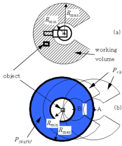
Fig. 2. (a) robot work space. (b) two of the feasible robot poses,
, to grasp the object are A and B.
feasible grasp poses at the pick up and put down sites can be expressed as
and .
In Fig. 1 below, the set of all gripper (robot hand) poses that are generated by rotating the hand about the axis ygconstitutes the grasp poses satisfying the grasp constraints and collision constraints (since there is no other object to cause gripper collision), . Arm kinematic and motion constraints still need to be checked in order to be used for an actual grasping operation. The following theorem is useful for checking the existence of a PNP operation without a re‐grasping step between the pick up and put down motions.
Theorem 1. It is necessary that ∩≠ , for the existence of a common grasp pose, g, that can be used for both pick‐up and put‐down motions so that the re‐grasping step is not necessary for the PNP operation.
Fig. 1. Grasping geometry.
2.2 Pick‐and‐Place Task for Mobile Manipulator Compared to PNP operation of a manipulator, PNP of a mobile manipulator has two more steps. They are moving the mobile base at the beginning so the object to be grasped is within the workspace of the manipulator, and moving the base after the grasp so the target pose of the object for put‐down operation is within the workspace. Fig. 2(a) shows a top‐down view
of a manipulator’s workspace. For a grasp operation, the object has to lie within the donut‐shaped region bounded by the minimum radius (Rmin) and the maximum radius (Rmax) of the robot’s workspace. If there is a limit on the base joint of the manipulator, the donut is clipped to a C shape. At the same time, the robot should not collide with other objects in its workspace. There are usually infinitely many robot poses (Pr) that satisfy both the workspace and collision constraints. The furthest pose from which the robot can grasp an object is when the object lies on the outer boundary circle, while the closest pose is when it lies on the inner boundary circle.
Similarly, to the grasp poses, let denote the set of all kinematically feasible, collision‐free robot poses from which to pick up (put down) an object. The C shapes in Fig. 2(b) represent only kinematically feasible robot poses, . If we further impose the constraints that the robot’s body and arm do not collide with other objects, we get .
Optimal robot poses for both the pick and place operations need to be selected from these sets, which are in turn checked for compatibility with grasp poses and the existence of collision‐free motions of the robot body and arm.
For the example task shown in Fig. 3, the user
Fig. 3. A pick‐and‐place task for a mobile manipulator
command is simply “move the object in Pose a on Table at left to Pose b on Table at right.” The robot’s base pose can be either Pose ri1 or ri2 to grasp the object, and rt1 or rt2 to put down the object.
When both of the initial and the target poses of the object do not lie in the same workspace, a collision‐free path from the initial pose to the target pose of the robot base must exist to complete the PNP operation. There are many algorithms for path planning or navigation planning[12,13] that runs in near real‐time.
2.3 Robot Pose Selection Strategy for Pick‐
and‐Place Task
Previous research on the pick‐and place task can be found in [10], where a planning algorithm is proposed to move an object from an initial pose to a target pose with a robotic arm. This algorithm builds a grasp look‐
up table that enumerates all kinematically feasible grasp poses for each point in the robot’s workspace at a preset interval. Once this table is built for a particular manipulator, it can be used repeatedly to solve PNP problems for that manipulator. When searching for the optimal grasp pose, each of the grasp poses in the table is tested for geometric feasibility in real‐time. The algorithm then generates a sequence of moves to move the object to the target pose, which possibly include a re‐grasp step between the pick‐up and put‐down operations.
This research makes use of the grasp look‐up table to find a sequence of moves so that a mobile manipulator can perform PNP operations. We model a mobile
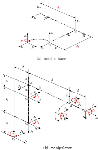
manipulator in two ways: a combination of a mobile base (3 dof) and a manipulator (6 dof), and one continuous linkage from the robot base to the manipulator hand (9 dof). The mobile base is modeled as a 3‐dof linkage consisting of two prismatic joints for its position (x, y) and one rotary joint for its orientation.
Fig. 4 (a) and (b) respectively show the kinematic modeling using the Denavit‐Hartenberg (DH) notation for the mobile base and the manipulator. We use this dual modeling method because depending on the complexity of a PNP task, we may need a sequence of 3‐dof and 6‐dof motions, or we may need a series of continuous 9‐dof motions.
Fig. 4. Kinematic modeling of the base and manipulator
3. Algorithm
Our robot base pose determination algorithm works in
Fig. 5. Flow chart for the overall algorithm two steps. First, it builds the feasible grasp look‐up
table, and based on this table, the robot determines the optimal base poses to pick up and put down the object.
3.1 Pose selection strategy for pick‐and‐
place task
The robot workspace is partitioned into a set of nodes by sampling each of the axes radius (r), pan(θ) and tilt (φ) at fixed intervals. A local rectangular coordinate system (xn, yn, zn) is then placed at each node, where xn, yn, zn denote the unit vector representing the x, y, z axis of nth node’s coordinate system. We then rotate the local coordinate system about zn by an angle α and about xn, by an angle β at a regular interval to generate dense samples of possible grasp orientations for the robot hand.
For each of the grasp pose at each node, we compute inverse kinematic solutions. The poses with a solution constitute the kinematically feasible grasp poses for each hand position of the robot’s workspace. For the FARA AS2 manipulator we use, there are 2380 nodes representing the workspace, and for each node there are 648 grasp poses, resulting in 1,542,240 grasp poses. To select kinematically feasible grasp poses, the resolved motion rate control (RMRC)[11] is used to move the robot hand from its home position in a straight line. In applying RMRC, we assume the floor is the only object in the robot’s workspace. When there is a kinematic singularity on the straight‐line path, RMRC may not find an inverse kinematic solution at the grasp pose. In such cases, the robot arm is placed in a configuration with a maximal manipulability before moving on the straight line to increase the chance of avoiding singularities and finding a solution.
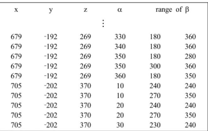
All the kinematically feasible grasp poses (αn, βn) found this way is stored in a table indexed by(xn, yn, zn) and is called the (kinematically feasible) grasp look‐up table (see Table II for an example). As mentioned before, this table is computed once for a manipulator and used repeatedly in any work environment. Because of this, we are able to afford the computation of over a million grasp poses.
x y z α range of β
⋮
679 679 679 679 679 705 705 705 705 705
‐192
‐192
‐192
‐192
‐192
‐202
‐202
‐202
‐202
‐202
269 269 269 269 269 370 370 370 370 370
330 340 350 350 360 10 10 20 20 30
180 180 180 300 180 240 270 240 270 230
360 360 280 360 350 240 350 240 350 240 Table 1. An example of a grasp look‐up table
3.2 Determination of Robot’s Base Poses Depending on whether or not the robot can execute the pick‐and‐place operation from a fixed base pose, we have developed two separate algorithms. Let (Rmax)pu and (Rmax)pd be the largest distances at which the robot can grasp an object at the pick‐up and put‐down locations, respectively. Depending on whether the distance between the pick‐up position and the put‐down position is greater than (Rmax)pu+(Rmax)pd, different algorithms are developed as described below. The overall flow of these algorithms is shown in Fig. 5.
3.2.1 Base Pose selection for pick‐up tasks
The problem of determining the robot’s base pose for picking up an object is equivalent to that of determining the pose for put‐down operation. Thus, we will only describe the algorithm for pick‐up operation. The robot’s base pose has to be selected among those that are kinematically feasible and geometrically feasible (no collision), which we denote as . The grasp pose look‐up table that has been pre‐computed is utilized to perform the search in a short time. From the look‐up table, we select all the nodes whose z coordinate is within a small distance from the z coordinate of the object to be grasped. The x and y coordinates are the positions of the nodes relative to the robot base coordinate frame in the 2D plane. The absolute position of the robot base that enables grasping of an object at one of the nodes can be anywhere between the two circles of radii Rmaxand Rmin centered at the node, i. e.,
Rmin≤(x - xnode)2+(y - ynode)2≤Rmax (1)
We have already verified during the look‐up table build‐up the kinematic feasibility. Among all such nodes, we select those that do not cause collisions between the robot and the objects in the environment, and sort them by the distance from the robot’s starting position in the increasing order. The final pose of the robot base for the pick‐up operation can be written as
(2)One thing that needs to be done at this point is to align the orientation of the robot base, θ0, so the robot arm is pointed toward the object to be grasped. The θ0
can be easily computed from the node position with respect to the robot base coordinate frame as follows:
θ0= cos-1(x/r) (3) where x, y are the x, y coordinates of the node and
After the robot moves to the pose of one of the nodes, the pose of the object to be grasped is computed as
(4)
where is the object frame w.r.t the world frame.
Besides the proximity of the nodes to the robot’s starting position, we also prefer the grasp pose with the largest grasp angle range, β. This gives the best chance to find a kinematically feasible, collision‐free robot base pose for picking up the object.
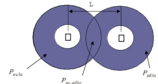
3.2.2 Base pose selection for both pick‐up/place tasks Generally speaking, accurate control of a mobile robot is often hampered by the wheel slippage and errors in the odometer sensing[1]. For a manipulator, repeated calibration and visual servoing are done to increase the accuracy of its operation. It is, therefore, advantageous to pick‐up and put‐down an object from the same robot base position. To do so, a grasp pose keinematically and geometrically feasible at the pick‐up site must be also feasible at the put‐down site. Let {} and {} be the set of all feasible grasp poses at the pick‐up and put‐
down sites, respectively. Then the pick‐and‐place operation can be performed from a fixed robot base pose if
≡
∩
≠ (5) which is a restatement of Theorem 1.Fig. 6 shows the two donut‐shaped regions that represent {} and {}. Their intersection is the set of possible grasp pose that are kinematically and geometrically feasible at both sites. A node that does not cause a collision between the robot and the objects in the environment and that offers the maximum grasp angle range is then selected as the final pose of the robot base.
Fig. 6. Kinematically feasible robot position for pick‐up/put‐down poses.
4. Grasp and motion planning algorithm
The algorithm in Section III finds the robot base poses that are kinematically and geometrically feasible for a PNP operation, but are not fully qualified as a solution yet. In some cases the pose may cause a collision between the gripper and the object to be grasped. In other cases, the robot arm may be trying to reach the object from one of the chosen base poses, but there may not be a collision‐free path for the arm. In still other cases, a feasible base pose may not be reachable by the mobile base from the current pose of the robot. We therefore use a grasp planner and a motion planner to eliminate the base poses falling into these three cases.
4.1 Grasp Planning
To achieve a stable grasp, our grasp planner aligns the hand frame affixed to the midpoint between the two fingers of the gripper to the grasp frame affixed to near the object’s center of mass. The hand frame is then rotated about the y axis of the grasp frame by an angle β at preset intervals in order to find the angles that do not cause collisions between the gripper and the object to be grasped and/or other objects near the gripper (see Fig. 1). Only the grasp poses that pass this test are used for further processing.
4.2 Path and Motion Planning
To find a collision‐free path of the shortest length for the mobile base, we can use A* search, a Voronoi diagram, randomized search or plain grid search
algorithms. These path planners have been well developed in the past decade[12-14].
Finding a short, collision‐free arm motion is performed in three steps. First, RMRC is used to move the hand to the grasp pose in a straight line. If there is a collision during this motion, a more complete motion planner such as SANDROS[15] is used to find a collision‐
free motion, which guarantees the solution if one exists, up to a certain resolution. If there is no inverse kinematic solution due to an encounter with a kinematic singularity, we can either choose a different grasp pose or use the full 9 dof of the mobile manipulator to get around the singular point. We can also use the algorithm by G. Marnani to avoid singularities[16]. In our experiments, most cases are solved using only the first two steps.
5. Simulation Experiments
Our algorithm is implemented in C programming language, and verified in simulation using OpenGL in Windows environment. Shown below are two simulations: the first task executable with a fixed robot base pose, the second requiring the robot base to move.
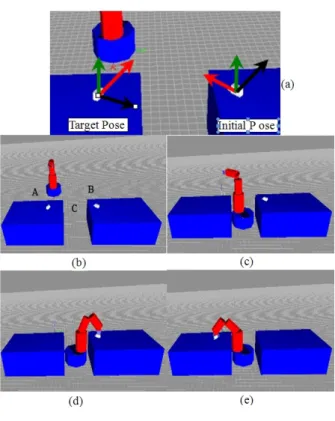
When the distance between the pick position and put down is less than (Rmax)pu+(Rmax)pd, it is advantageous to perform the PNP operation using only the manipulator arm from a fixed robot base pose in order to minimize control errors. Fig. 7(a) shows the target pose and initial pose of the block, and (b) shows the scenario of moving a block from the table on the right to the left. Although it is possible to pick up the block from base pose B, move the base to pose A, and put the block down from there, it is better to find a base pose like C (Fig. 7(c)), from which the robot can perform both the pick‐up and put‐down operations (Fig. 7(c)‐(d)). It took about 8 mili‐
second to find such a pose between the two tables.
When the distance between the pick position and put‐
down position is greater than (Rmax)pu+(Rmax)pd, our algorithm finds separate base poses for pick‐up and put‐
down operations. The robot then has to move between these poses. Fig. 8(a),(b) show the orientation of block
Fig. 7. Simulation example 1
Fig. 8. Simulation example 2
at target pose and initial pose, and (c) shows a case where the block’s starting point is too far from the table where the block is to be placed. Our algorithm chooses base pose B to pick up the block and pose D for the final placement of the block. Poses like C are eliminated
since they cause a collision between the robot and the table when trying to put down the object. On a typical PC, it took less than 1 second to find Pose B and D.
6. Conclusions
We have presented an optimal robot pose determination algorithm for service robots so that they are capable of performing pick‐and‐place operations reliably in everyday human‐living environments. The efficient performance of this algorithm is verified by simulation results. The proposed algorithm finds a solution in 1 second, and it is combined with a collision‐
free motion planning algorithm to develop a complete pick‐and‐place algorithm for mobile manipulators.
The future work includes the integration of visual servoing into our current algorithm. Our algorithm assumes that the robot has perfect control and has accurate models of the objects in its workspace. Because of modeling errors and errors in the robot’s pose due to control error, visual servoing is necessary to correct these errors. When this is done, we are going to have a truly autonomous robot system that can transport/transfer objects without detailed human instructions.
References
[1] D Berenson, J Kuffner, H Choset, "An optimization approach to planning for mobile manipulation", Proc. IEEE Int. Conf. on Robotics and Automation, pp.1187‐1192, 2008.
[2] J. Tan, N, Xi, "Integrated Task Planning and Control for mibile Manipulators", Proc. IEEE Int.
Conf. on Robotics and Automation. pp.382‐387, 2002.
[3] O. Brock, O. Khativ, S. Viji, "Task‐Consistent Obstacle Avoidance and Motion Behavior for Mobile Manipulation", Proc. IEEE Int. Conf. on Robotics and Automation. pp.388‐393, 2002.
[4] Y. Yamamoto, X. Yun, "Unified Analysis on Mobility and Manipulability of Mobile
Manipulators", Proc. IEEE Int. Conf. on Robotics and Automation, pp.1200‐1206, 1999.
[5] L. Petersson, P. Jensfelt, D. Tell, M. Strandberg, D. Karagic, H. I. Christensen, "System Integration for Real‐World Manipulation Tasks", Proc. IEEE Int. Conf. on Robotics and Automation, pp.2500‐2505, 2002.
[6] T. Takahama, K. Nagatani, Y. Tanaka, "Motion Planning for Dual‐arm Mobile Manipulator ‐ Realization of "Tidying a Room Motion", Proc.
IEEE Int. Conf. on Robotics and Automation, pp.4338‐4343, 2004.
[7] R. David, P. Gavin, W. Stephen, K. Nathan,
“Manipulator‐Based Grasping Pose Selection by means of Task‐Objective Optimization”, ACRA, Vol. 2, pp 457‐462, 2010.
[8] 조경래, “집기‐놓기 작업을 위한 머니퓰레이터를 장착한 이동로봇의 위치선정”, 동서울대학 논문집, 2004.
[9] T. Lozano‐Perez, J. L. Jones, E. Mazer, P. A.
O'Donnell, "HANDEY : A Robot Task Planner", The MIT Press, Cambridge, Massachusetts, London, England.
[10] K. Cho, M. Kim, J‐B, Song, "Complete and Rapid Re‐grasp Planning with Look‐up Table", Journal of Intelligent and Robotic Systems, Vol.
36, pp.371‐387, 2003.
[11] D. E. Whitney, "The Mathematics of Coordinated Control of Prosthetic Arms and Manipulators", ASME Transactions on Dynamic Systems, Measurement and Control, Vol. 4, No 94, pp.
303‐309, 1972.
[12] T. Lozano Perez and M. A. Wesley, “An algorithm for planning collision‐free paths among polygonal obstacles,” Commun. ACM 22, 10 (Oct.), 560‐570.
[13] H. Noboria, T. Nantwa and S. Arimoto, “A feasible motion planning algorithm for a mobile robot on a quadtree representation, Proc. IEEE Int. Conf. on Robotics and Automation, pp.327‐
332, 1989.
[14] Y. K. Hwang and N. Ahuja, “Gross motion planning – a survey,” ACM Computing Surveys, 24, 3 (Sep.), 1992.
[15] P. C. Chen and Y. K. Hwang, "SANDROS: a Dynamic Graph Search Algorithm for Motion Planning," IEEE Transactions on Robotics and Automation, Vol. 14, No. 3, pp. 390‐403, Feb 1998.
[16] G. Marnani. J. Kim, J. Yuh, and W.K. Chun, "A real‐time approach for singularity avoidance in resolved motion rate control of robotic manipulators," Proc. IEEE Int. Conf. on Robotics and Automation. pp.1973‐1978, 2002
조 경 래
1988 인하대학교 기계공학과 (공학사)
1990 인하대학교 기계공학과 자동화공학 전공(공학 석사)
2000 고려대학교 기계공학과 메카트로닉스 전공 (공학박사)
1990~2001 한국과학기술연구원 휴먼로봇센터 선임 연구원
2001~현재 동서울대학교 항공자동차기계공학부 관심분야 : 모바일 머니퓰레이션, 자율주행로봇의
제어구조