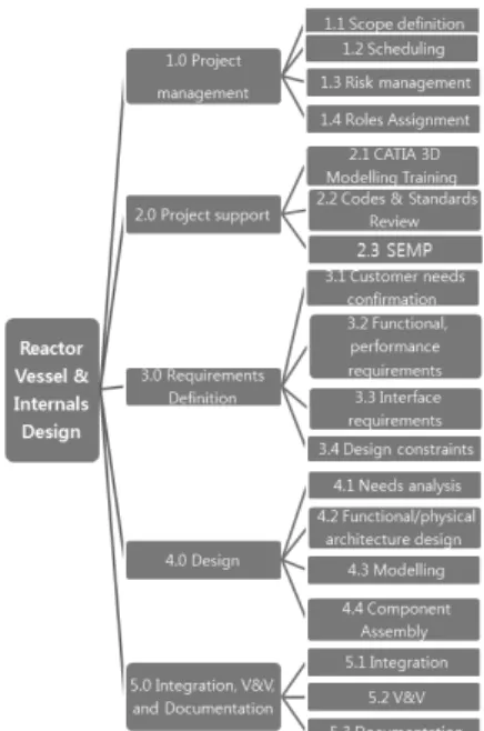
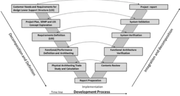
Design Re-engineering of the Lower Support Structure of the APR1400 Reactor Internals
7
0
0
전체 글
(2)
(3)
(4)
(5)
(6)
(7)
수치
관련 문서
To this end, prior studies of the type of value, design paradigm and design value were considered, and three types of design value (practical value,
The design method for the optimization of FRP leaf spring is proposed by applying design method of experiment in order to improve the characteristics of
Evaluating the impact of a facilitated learning community approach to professional development on teacher practice and student achievement.. Engineering by
The characteristic change according to the main design parameters of the magnetic gear can be confirmed, and the difference in loss and efficiency according
이상해결책과 물리적 모순의 정의(defining ideal final result(IFR) and physical contradiction). – 3.1
1 John Owen, Justification by Faith Alone, in The Works of John Owen, ed. John Bolt, trans. Scott Clark, "Do This and Live: Christ's Active Obedience as the
○ In the future, the goals of Korea’s international agricultural development cooperation projects should be connected with SDGs, and it is important to
Design is applied to create better convenience and beneficial values through a variety of design methodology in relevant industry, and new service
