• 검색 결과가 없습니다.

High Temperature Corrosion of Ni-17%W Coatings in Ar-0.2%SO<sub>2</sub> Atmosphere

N/A
N/A
Protected

Academic year: 2021

Share "High Temperature Corrosion of Ni-17%W Coatings in Ar-0.2%SO<sub>2</sub> Atmosphere"

Copied!
5
0
0

로드 중.... (전체 텍스트 보기)

전체 글

(1)

한국표면공학회지 J. Kor. Inst. Surf. Eng.

Vol. 43, No. 1, 2010.

<연구논문>

High Temperature Corrosion of Ni-17%W Coatings in Ar-0.2%SO 2 Atmosphere

Dong-Bok Lee

a*

, Sik-Chol Kwon

b

a

School of Advanced Materials Science and Engineering, Sungkyunkwan University, Suwon 440-746, Korea

b

Functional Coatings Group, Korea Institute of Materials Science, Changwon 641-010, Korea (Received February 2, 2010 ; revised February 26, 2010 ; accepted February 27, 2010)

Abstract

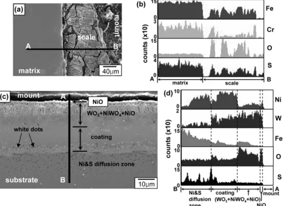
Coatings of Ni-17 at.%W were electroplated on a steel substrate, and their corrosion behavior was inves- tigated between 600 and 800

o

C in an Ar-0.2%SO

2

atmosphere. They delayed the corrosion of the steel substrate.

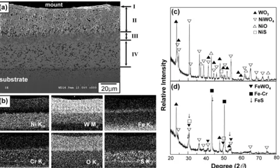
They were corroded into an outer NiO-rich layer, and an inner (WO

3

+NiO+NiWO

4

)-mixed oxide layer. Below these oxide layers, a sulfide layer gradually formed.

Keywords: Nickel, Tungsten, Sulfidation, Oxidation, Electroplating

1. Introduction

Electrodeposited hard Cr coatings are widely applied as wear- and corrosion-resistant ones, but the Cr- plating solution is based on environmentally hazardous hexavalent Cr ions. Hence, the Ni-W coatings were developed as an alternative electrodeposit

1,2)

. They have high hardness, good resistance to wear and corrosion, a smooth surface, chemical stability in a fluoride-containing atmosphere, and thermal stability as protective coatings

3,4)

. In this study, Ni-17at.%W coatings were electrodeposited, and their corrosion characteristics in the Ar-SO

2

atmosphere were studied.

It is noted that tungsten displays the sulfidation resistance because it sulfidizes to WS

2

, which exhibits a very low deviation from stoichiometry. WS

2

is an exceptional sulfide that grows slowly in sulfur atmospheres. However, sulfidation-resistant tungsten oxidizes catastrophically to volatile W-oxides at high temperatures. Hence, one would need to compromise between oxidation resistance and sulfidation resistance when designing a Ni-W coating to utilize in the SO

2

environments. On the other hand, nickel has reasonable oxidation-resistance by forming NiO, although its

sulfidation-resistance is poor because of rapid diffusion of ions through the highly nonstoichiometric Ni- sulfides formed

5)

. This study was initiated with the expectation that the combination of Ni and W may provide the Ni-W coatings with the necessary oxidation-resistance owing to the presence of Ni and sulfidation-resistance owing to the presence of W.

The aim of this study is to characterize the corrosion behavior and to find the corrosion mechanism of Ni- W coatings in the Ar-SO

2

atmosphere, which was not adequately investigated before.

2. Experimental Procedure

Ni-17at.%W coatings were electrodeposited from NiSO

4

·6H

2

O (i.e., Ni source) and Na

2

WO

4

·2H

2

O (i.e., W source) solution on both sides of the STD 61 (4.5 wt.% Cr-containing steel) plate to 40 µm-thickness.

The electrodepositing procedure is described elsewhere in detail

6)

. The Ni-17W coated steel specimens were corroded between 600 and 800

o

C in Ar-0.2%

SO

2

atmosphere for up to 5 hr, and were investigated utilizing a scanning electron microscope (SEM) equipped with an energy dispersive spectrometer (EDS), an Auger electron spectroscope (AES), and an X-ray diffractometer (XRD) with Cu-K

α

radiation.

*

Corresponding author. E - mai l : [email protected]

(2)

3. Results and Discussion

Fig. 1 shows the analytical results of the Ni-17W coating after corrosion at 600

o

C for 5 hr. The scale that formed on the sound coating consists primarily of an inner, thick layer, and an outer, thin layer that was detached (Fig. 1(a)). The corrosion products are

mainly WO

3

, together with some NiWO

4

and a small amount of NiO (Fig. 1(b)). No sulfides are however detected from XRD owing to their small amount, as can be noticeable from the low counts of S in Fig. 1(c).

From Fig. 1, it can be seen that the thin, outer scale consists mainly of NiO, while the thick, inner scale consists of a mixture of WO

3

, NiWO

4

and NiO. It is

Fig. 1. Ni-17W coating after corrosion at 600

o

C for 5 hr in Ar-0.2%SO

2

. (a) cross-sectional SEM image, (b) XRD pattern, (c) EDS line profiles across A-B.

Fig. 2. After corrosion at 700

o

C for 5 hr in Ar-0.2%SO

2

. (a) cross-sectional SEM image of the uncoated steel substrate,

(b) EDS elemental line profiles of (a), (c) cross-sectional SEM image of the Ni-17W coating, (d) EDS elemental

line profiles of (c).

(3)

clear that NiO partially reacted with WO

3

to be the more stable NiWO

4

at the inner scale. The uneven thickness of inner, mixed scale shown in Fig. 1(a) is mainly originated from the uneven distribution of Ni and W in the coating. The composition of Ni-17W denoted in this study is the average value determined by EPMA. It varied locally, which was difficult to avoid during electroplating. The corrosion products of the Ni-W coatings would depend on potential of oxygen and sulfur in the gas, and activities of Ni and W in the coating. In this study, the oxidizing tendency was stronger than the sulfidizing tendency, implying that the oxides were the more stable than the sulfides under the current Ar-0.2% SO

2

gas atmosphere.

Fig. 2 compares the uncoated steel specimen and the Ni-17W coated specimen, when they were corroded at 700

o

C for 5 hr. The scale formed on the uncoated specimen was quite thick, non-adherent, and susceptible to cracking (Fig. 2(a)). The scale consists primarily of the (Fe,Cr)-oxides and sulfides (Fig. 2(b)). In contrast to the rapid corrosion of the steel specimen displayed in Fig. 2(a), the steel substrate was effectively protected from corrosion by the coating in Fig. 2(c). Here, the scale consisted primarily of an outer NiO layer and the inner (WO

3

+NiO+NiWO

4

)-mixed layer, as shown in Fig.

2(d). Iron diffused out from the substrate to be incorporated in the oxide-rich scale. The retained coating on the steel substrate was rich in Ni, but deficient in W (Fig. 2(d)). Nickel partly penetrated inwardly from the coating to the substrate, according to the concentration gradient. A large portion of W in the coating was consumed to form the oxide scale.

Sulfur penetrated beyond the coating/substrate interface.

At the coating just above the substrate, numerous white dots are seen. They were previously found to be as the Ni-Fe-W precipitates that were formed mainly by the reaction of outwardly transported Fe with Ni and W next to the coating/substrate interface

6)

. Because of the high atomic number of W, the Ni-Fe- W precipitates show up as white dots in Fig. 2(c).

Although the upper part of the Ni-W coating has the corrosion layers and sulfur has diffused beyond the coating/substrate interface, the substrate appears to be sound in Fig. 2(c), which is quite different from Fig. 2(a). Nevertheless, the formation of various oxides and sulfides in the corroded specimen would eventually lead to the failure of the coating and the substrate.

A marker experiment was performed to study the corrosion mechanism of the Ni-17W coating, and the

result is shown in Fig. 3. From the location of Pt, it is seen that Ni and some W diffused outward, while oxygen diffused inward simultaneously. Platinum was sputter-deposited on the sample surface prior to corrosion to indicate the original sample surface. The outer NiO-rich layer grows by the outward transport of Ni via doubly charged cationic vacancies, because the self-diffusion of oxygen is smaller than that of nickel by several orders of magnitude in NiO

7)

. Ni atoms diffuse about 3~4 times faster than W atoms in the Ni-W alloy system at high temperatures

8)

. The inwardly transported oxygen forms the inner (WO

3

+ NiO+NiWO

4

)-mixed layer. Sulfur was not detected in Fig. 3 owing to its meager amount during the initial corrosion stage.

Fig. 4 shows the analytical results of the Ni-17W coating after corrosion at 800

o

C for 5 hr. In Fig. 4(a), the layer I is the outer NiO-rich scale, which was formed by selective oxidation of Ni at the outer surface. The layer II is the inner (WO

3

+NiWO

4

+ NiO)-mixed scale, as can be seen in Fig. 4(b).

Together with oxides of WO

3

+NiO+NiWO

4

, a small amount of NiS was also detected in Fig. 4(c). The presence of Fe in the layer III, i.e., in the middle of the corroded Ni-W coating, again indicates that Fe diffused out from the substrate owing to the concentration gradient between the coating and the substrate during corrosion. At the same time, Cr diffused outwardly from the substrate, but to a lesser amount owing to its low concentration in the substrate.

Around the coating/substrate interface, Fe existed as FeWO

4

and FeS, although their amount was small (Fig. 4(d)). Besides FeWO

4

and FeS, the XRD tests also sometimes indicated the presence of NiFe

2

O

4

Fig. 3. AES depth profile of Ni-17W coating after

corrosion at 800

o

C for 2 min in Ar-0.2%SO

2

. The

penetration rate is 180 Å/min for the reference

SiO

2

.

(4)

and Fe

2

O

3

as the corrosion products of Fe. Dark spots in the layer II are either internal oxide precipitates or micropores. Pores can be formed by either outward diffusion of Ni, which forms the outer NiO-rich layer, or the anisotropic volume expansion during oxide formation. Scattered dark spots in the layer IV correspond with sulfide precipitates of Ni, W, Fe, and Cr, which were formed by the sulfur that diffused inwardly from the atmosphere. White dots shown in Fig. 2(c) are no longer seen in Fig. 4(a) due to the excessive corrosion in the layer IV. Beneath the corroded Ni-W coating, not W but Ni has diffused significantly into the substrate (see the Ni map in Fig. 4(b)). The diffusion of oxygen, sulfur and cationic species along short-circuit paths such as the grain boundaries of nanocrystalline Ni-W coatings would be fast

6)

. As the oxide layer thickens from the upper part of the coating, the oxygen potential underneath is continuously decreased. This, in turn, increases the activity of S in the lower part of the coating, leading to the formation of the sulfides in the layer IV (Fig.

4(b)). The above results indicate that, from the surface, there are an outer, thin NiO-rich oxide layer, an inner, thick mixed oxide layer of (WO

3

+NiO+

NiWO

4

), a thin, intermediate Fe-rich oxide layer, and a thick, bottom layer that consisted mainly of sulfides of (Ni + some Fe, Cr and W). In the scale, NiO and FeO frequently combine WO

3

to become the

more stable NiWO

4

and FeWO

4

spinels, respectively.

The formation of these spinels would reduce the cross-sectional area available for ionic diffusion.

Unfortunately, the sulfidation-resistant phase, WS

2

, was not detected from any XRD tests, due to either its small amount or absence. Most of W in the coating was consumed to form WO

3

, NiWO

4

and FeWO

4

, owing to their thermodynamic stability. Diverse corrosion products such as NiO, WO

3

, NiWO

4

, NiS, FeWO

4

and FeS were detected in this study.

4. Conclusions

The principal mode of corrosion and scale morphologies of the Ni-W coatings in the SO

2

- containing atmosphere was examined. The sulfides formed were NiS and FeS. The oxides formed were WO

3

, NiO, NiWO

4

and FeWO

4

. The corrosion started from the formation of the outer NiO-rich layer, an inner (WO

3

+NiO+NiWO

4

)-rich mixed layer.

Below these oxide layers, a thin, intermediate Fe-rich oxide layer, and a thick, bottom layer that consisted mainly of sulfides of (Ni + some Fe, Cr and W) gradually formed, as the corrosion progressed. During corrosion, Ni and some W and Fe diffused outwardly toward the outer NiO-rich layer, and oxygen and sulfur diffused inwardly to form the internal layers of oxides and sulfides.

Fig. 4. Ni-17W coating after corrosion at 800

o

C for 5 hr in Ar-0.2%SO

2

. (a) cross-sectional SEM image, I=outer NiO-

rich layer, II=inner mixed oxide layer, III=intermediate oxide layer, IV=bottom sulfide layer, (b) EDS elemental

mappings of Ni. W, Fe, Cr, O and S, (c) XRD pattern taken from the surface side of the scale, (d) XRD pattern

taken after removing most of the surface scale.

(5)

Acknowledgement

This work is the outcome of a Manpower Development Program for Energy & Resources supported by the Ministry of Knowledge and Economy (MKE).

References

1. K. H. Kim, K. H. Cho, J. Kor. Inst. Surf. Eng., 40 (2007) 131.

2. H. S. Chu, D. K. Kim, J. Kor. Inst. Surf. Eng., 41 (2008) 312.

3. T. Yamasaki, P. Schlo β macher, K. Enrlich, Y. Ogino, NanoStruct. Mater., 10 (1998) 375.

4. T. Omi, M. Nakamura, H. Yamamoto, J. Surf.

Finishing Soc. Jpn., 39 (1988) 809.

5. N. Birks, G. H. Meier, F. S. Pettit, Introduction to the High-Temperature of Metals, 2nd ed, Cambridge University Press, England, (2006) 163.

6. D. B. Lee, J. H. Ko, S. C. Kwon, Mater. Sci. Eng.

A, 380 (2004) 73.

7. R. Peraldi, D. Monceau, B. Pieraggi, Oxid. Met., 58 (2002) 275.

8. K. Monma, H. Suto, H. Oikawa, J. Jpn. Inst. Met.

28 (1964) 197.

수치

Fig. 1. Ni-17W coating after corrosion at 600 o C for 5 hr in Ar-0.2%SO 2 . (a) cross-sectional SEM image, (b) XRD pattern, (c) EDS line profiles across A-B.
Fig. 2 compares the uncoated steel specimen and the Ni-17W coated specimen, when they were corroded at 700 o C for 5 hr
Fig. 4. Ni-17W coating after corrosion at 800 o C for 5 hr in Ar-0.2%SO 2 . (a) cross-sectional SEM image, I=outer NiO- NiO-rich layer, II=inner mixed oxide layer, III=intermediate oxide layer, IV=bottom sulfide layer, (b) EDS elemental mappings of Ni

참조

관련 문서

자석 팽이는 볼록한 두 부분에는 고리 자석이 들어 있고, 받침대에는 팽이의 고 리 자석 위치와 일치하는 부분에 삼각형 모양의 자석이 네 개 들어 있다.. 그리고

CMP process is effectively used to flat dielectric layer such as IMD, ILD, PMD and metal layer such as W, Al, Cu in order to perform multi layer

Introduction to Data Communication Networks, M2608.001200, 2021 FALL SEOUL NATIONAL

This research was supported by Korea Atomic Energy Research Institute (NTIS-1711139325) and National Research Foundation of Korea (NRF) Grant funded by the Korean

• Inertial sub-layer, viscosity plays a minor role. • Main turbulent

pottery, tableware, cookware, building materials, aerospace materials, to nuclear materials (e.g., UO 2 pellets, waste forms, etc.)... A’ a’ B’ b’ C’

Decomposition (MOD) process, and then the zinc oxide nanorods on ZnO seed layer were grown by hydrothermal process from 0.3 M at pH 7, 80 ℃ , 1 h. Single phase zinc oxide

• Prandtl (1904) suggested the boundary layer concept in which viscous effects are important only in the boundary layer regions, and outside boundary layer, the fluid acts as