Design and Implementation of Internal Multi-Band Monopole Antenna for Mobile Phones
Woon Geun Yang
*★, Ling Zhi Cai
*, Cheol Yong Yang
*Abstract
In this paper, we proposed an internal multi-band monopole antenna for mobile phone that can be used for smart phones. The proposed antenna has a small volume of 38×8.5×5 mm
3, ground size is 100×60 mm
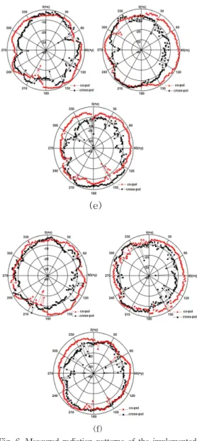
2, and covers the GSM900 (Global System for Mobile communications : 880-960 MHz), DCS (Digital Communications System : 1710-1880 MHz), K-PCS (Korea-Personal Communications Service : 1750-1870 MHz), US-PCS (US Personal Communications Service : 1850-1990 MHz), Bluetooth (2400-2483 MHz), Wibro (2300-2390 MHz) and WLAN (Wireless Local Area Network : 2400-2483.5 MHz) bands. The measured peak gains of the implemented antenna are 1.15 dBi at 920 MHz, 3.58 dBi at 1795 MHz, 3.46 dBi at 1810 MHz, 2.91 dBi at 1920 MHz, 5.18 dBi at 2345 MHz, 3.37 dBi at 2442 MHz.
Key words: Monopole, Multi-Band, Internal antenna, Folded
*
Dept. of Electronics Engineering, University of Incheon
★