Water-jet Cleaning Motion of the In-Pipe Robot with Screw Drive Inside the Water Pipes
Hoon Kang1․Jin-Seok Oh†
(Received September 6, 2012; Revised November 19, 2012; Accepted November 19, 2012)
Abstract:For more efficient use of the high pressure water-jet in rehabilitation of the water pipes, we have studied the water-jet cleaning motion of the in-pipe robot with screw drive. The mathematical models of the water-jet in the straight and the curved pipe (90 degrees elbow), representative features of the water mains, were designed to understand the water-jet motion and simulations have been performed. Furthermore the experiments has been conducted to validate the simulations by using the prototype in-pipe robot in the 3-D pipeline. The simulation results show that the water-jet motion in the straight pipe has a constant water-jet interval, whereas the motion in the curved pipe is changed by its position. By the comparison of the simulation and the experimental results, we have demonstrated that the simulations successfully estimate the water-jet motion inside the water pipes. Therefore in-pipe robot operators can predict a water-jet motion for a target water pipe through the simulation and flexibly make a proper water-jet motion by changing the robot configurations before a cleaning work.
Key words:Water-jet, In-pipe robot, Screw drive, Water pipe, Rehabilitation
†Corresponding Author (Division of Marine Engineering, Korea Maritime University, Email: [email protected], Tel:
051-410-4283)
1 Division of Mechatronics Engineering, Korea Maritime University, Email: [email protected], Tel: 051-410-4866
1. Introduction
In the modern society a pipe is indispensable part for a fluid transfer system and used in various industrial applications. Especially, a water pipe always has to ensure a stable water supply and a clean water quality because it is closely connected with our lives. However, deterioration of old water pipes which were installed about 20 years ago and the majority is suffering from corrosions on internal surface. As a result, corrosion products are gradually accumulated on the inner surface of water pipes and lead to a decline in water quality and discharge capacity [1].
To solve the problems that come from deterioration, many types of pipe renovation
technologies have been developed. These technologies are roughly divided into two methods, rehabilitation and replacement. Rehabilitation is a method to extend the life of old water pipes without a replacement. It does not involve a noise, a traffic control and a high construction cost because the excavation work that is necessary to replacement is totally unnecessary [2].
Rehabilitation is subdivided into two methods in detail, cleaning and lining method. Cleaning method is able to remove hard water scale as well as soft one which includes a microbial film and scale deposits. Cleaning method employs a high pressure water-jet, a metal scraper, chemicals and a grinder to clean the inner surface of water pipes. In
particular, a high pressure water-jet is utilized with a rotating mechanism, an in-pipe robot system and a water-jet gun. An in-pipe robot system is the most efficient way to use the high pressure water-jet because it is capable of moving the water-jet nozzle to an arbitrary position inside water pipes and cleaning the water pipes more faster than a worker using the water-jet gun.
Different types of in-pipe robots have already reported and those can be classified according to the drive mechanism that involves a wheel, a caterpillar, a leg and etc. The most common type of an in-pipe robot is a wheeled-robot and its drive mechanism has been modified by combining other drive mechanism for more efficient applications.
Especially an in-pipe robot with screw drive, so-called ‘a screw type robot’, is composed of wheel, wall-pressing and screw mechanism and runs with a helical motion inside a pipe [3]. The in-pipe robot with screw drive has a simple architecture that is suitable for a pipe with small diameter because only one actuator is required for drive [3-6]. That is, the in-pipe robot with screw drive can be smaller and lighter. Moreover the control becomes easier [3-4]. Mihaita Horodinca et al. [4]
and Shigeo et al. [5] developed the in-pipe inspection vehicles with screw drive for small sized pipelines within 150mm in diameter. Iwao Hayashi et al. [6] studied a screw-principle microrobot in a small bent pipe of 27mm in inner diameter. The reported studies only had been focused on the driving characteristics of a screw type robot and pipe inspection.
The current study represents the water-jet cleaning motion of the in-pipe robot with screw drive inside water pipes for more efficient use of the water-jet. In order to understand the water-jet cleaning motion, simulations and experiments have been performed. By comparing the simulation results with the experimental results we
demonstrated that the simulations estimate the water-jet motion successfully.
2. Mathematical Modeling
2.1 Robot architecture
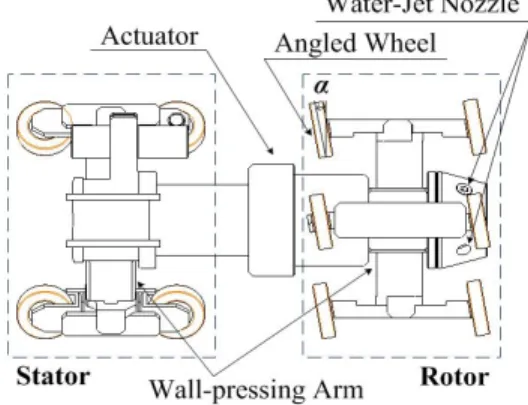
As aforementioned, the in-pipe robot with screw drive has a simple architecture as illustrated in Figure 1. The robot architecture is mainly made up of two parts, a rotor and a stator, connected by an universal joint [3-4]. The rotor equipped with the angled wheels rotates against the stator and simultaneously moves forward(or backward) like as a screw bolt when the actuator is working. On the other hand, the stator that has a set of parallel wheels does not rotate itself but it is passively moved forward(or backward) by a rotor’s translational motion. A water-jet nozzle installed in front of the in-pipe robot rotates along with the rotor and emits the high pressure water-jet onto the inner surface of a water pipe. Additionally the wall-pressing arms play an important role in maintaining a constant pressure between the wheels and the inner surface of the pipe [3, 7].
Figure 1: Robot architecture with screw drive
2.2 Mathematical model for a straight pipe
So as to estimate a motion of the water-jet in the water pipes, we designed two mathematical models for a straight pipe and a curved pipe. The
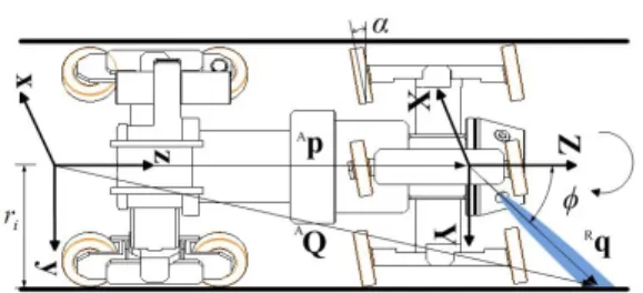
mathematical model for a straight pipe can be described as depicted in Figure 2.
Figure 2: Mathematical model of the water-jet in a straight pipe
Herein, xyz and XYZ denote an absolute coordinate system and a relative coordinate system respectively. The origins of both coordinate systems are located on a same axis, namely the center axis of a straight pipe. AQ denotes a position vector of the water-jet with respect to the absolute coordinate system, whereas Rq is another position vector of the water-jet with respect to the relative coordinate system. Ap denotes a position vector of the relative coordinate system from the origin under the absolute coordinate system. For reference, script ‘A’
and ‘R’ indicate a coordinate system, absolute and relative. Moreover, α and φ denote an inclined angle of the wheels in the rotor and a discharge angle of the water-jet on the YZ-plane, respectively.
ri also is an internal radius of a pipe. The in-pipe robot moves toward the +Z-axis in this mathematical model and the water-jet is emitted onto the inner surface. The water-jet trajectory in a straight pipe can be expressed by
AQ AHRRq
ARR Ap
Rq
cos sin sin cos ri tan
ritanϕri
(1)
where AHR is a homogeneous transformation matrix,
ARR is a rotation matrix and θ is a rotation angle
of the rotor around the +Z-axis. From the Equation (1) a moving distance(ds) of the in-pipe robot is derived by
tan (2)
In other words, the translational motion of the in-pipe robot with screw drive that means a moving distance(ds), is determined by a rotation angle of the rotor.
2.2 Mathematical model for a curved pipe
In case of cleaning the water pipes, the in-pipe robot with screw drive will run inside various features of the water pipes, such as T-shaped fittings, branches and various curved pipes, except for a straight pipe. Our in-pipe robot with screw drive can not run inside fittings and branches because the in-pipe robot is operated by only one actuator without a steering equipment. Thus, the in-pipe robot with screw drive just is able to move inside a simple curved pipe. A 90 degrees elbow, a representative feature of a simple curved pipe, is used for the mathematical modeling and the model of the water-jet can be expressed as depicted in Figure 3.
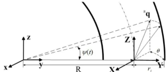
Figure 3: Mathematical model of the water-jet in a curved pipe(90 degrees elbow)
The center of curvature of the curved pipe is chosen as the origin of the absolute coordinate system. Herein, R denotes a radius of curvature of the curved pipe. The motion of the water-jet can be described that the water-jet rotates at an arbitrary position and at the same time the whole rotary parts move translationally inside the curved pipe.
Therefore, the understanding the water-jet motion is vital when the in-pipe robot just rotates at an arbitrary point without a translational motion. As shown in Figure 3, the water-jet is on the YZ-plane of the relative coordinate system. A unit vector of the water-jet(Ru) can be described as depicted in Figure 4.
Figure 4: Unit vector of the water-jet in a curved pipe
A water-jet vector is expressed as a multiplication of a unit vector by its length. The unit vector of the water-jet at a stationary point in a curved pipe can be written as
Ru
cos sin sin cos
cosϕsinϕ
sincosϕ
coscosϕ
sinϕ
(3)
Thus the water-jet vector, just rotates without a translation motion under the absolute coordinate system, is derived by
AQ
sin cosϕ Kt
cos cosϕ Kt R sinϕ Kt
, (4)
where K(t) denotes a length of the water-jet and it
can be changed by a rotation angle of the rotor(θ).
As shown in Figure 5, an angle of the water-jet with respect to the xy-plane is the other way to describe the water-jet vector in a curved pipe.
Figure 5: Angle of the water-jet with respect to xy-plane
Therefore the water-jet vector with respect to the absolute coordinate system can be expressed by
cos sin
sin cos
r sin
cosr cos R
sinr cos R
(5)
where Ψ(t) denotes an angle of the water-jet with respect to the xy-plane. Due to Equation (4) and Equation (5) are different expressions of the identical water-jet vector, K(t) and Ψ(t) can be obtained from the simultaneous equation as follows.
AqAw
AuzAwz
(6)
In this paper, we represent the water-jet motion in a curved pipe by using the unit vector with its length(K(t)) for convenient calculation. The distance that the in-pipe robot moves along a curved pipe is an arc length which is determined by a rotation angle of the rotor. In other words, the translation distance(dc) of the in-pipe robot in a curved pipe is calculated by
· tan (7)
where λ is an angle of the rotor with respect to xy-plane which means a position of the in-pipe robot in a curved pipe and can be expressed by
tan (8)
3. Simulation
3.1 Parameters and assumptions
In order to understand the water-jet cleaning motions in a straight and a curved pipe, simulations were performed. Parameters that involve the geometrical information of the target water pipes and the structural specifications of the in-pipe robot are listed in Table 1. Generally the water-jet discharge angle(φ) has to be between 90° and 150°
relative to the longitudinal axis of the pipe which indicates +Z-axis under the relative coordinate system. To simplify the mathematical models we considered some assumptions as follows:
∙The robot body is rigid
∙Slip between the robot wheels and the inner surface of the water pipes is ignored.
∙The actuator rotates with a constant angular velocity.
∙Forces are totally ignored.
Table 1: Specifications of the in-pipe robot system and the water pipes
Parameters Value
Radius of curvature of the curved pipe Internal radius of the pipe
Tilt angle of the wheel on the rotor Discharge angle of the water-jet Angular velocity of the actuator The number of water-jet nozzles
450 [mm]
150 [mm]
4 [°]
135 [°]
20 [rpm]
1
3.2 Simulation results
3.2.1 Simulation results for a straight pipe
In the straight water pipe the in-pipe robot
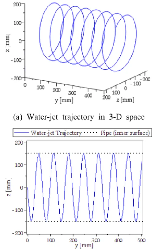
moves forward simultaneously with emitting the water-jet onto the inner surface. Figure 6 (a) shows the traveling trajectory of the water-jet with a helical motion in 3-D space. For better understanding of the water-jet trajectory, the trajectory in 3-D space is projected onto yz-plane as shown in Figure 6 (b).
(a) Water-jet trajectory in 3-D space
(b) Water-jet trajectory projected onto yz-plane Figure 6: Water-jet trajectory in a straight pipe
The moving distance of the in-pipe robot in one revolution of the actuator is equal to the water-jet interval between two collinear points that lies on a longitudinal axis of the straight pipe. The water-jet interval is a significant factor in a cleaning process because the entire area of the inner surface of the water pipes has to be covered by the water-jet for complete cleaning. The water-jet interval in the straight pipe can be calculated from Equation (2), approximately 65.9mm in this case.
3.2.2 Simulation results for a curved pipe
The in-pipe robot moves along with an arc trajectory and the water-jet presents a curved helix in the curved pipe. Especially the water-jet emitted onto the inner surface of the curved pipe makes an irregular trajectory as shown in Figure 7.
(a) Water-jet trajectory in 3-D space
(b) Water-jet trajectory projected onto yz-plane Figure 7: Water-jet trajectory in a curved pipe
The water-jet interval in the curved pipe is changed by its position. As shown in Figure 7 (b), the maximum interval of the water-jet is attained at the outer arc which is the farthest part from the center of curvature. Due to the maximum interval is always located in the outer arc, an angle between two neighboring points of the maximum interval is equal to λ, as defined above. Therefore
the water-jet interval can be calculated by using Equation (8), approximately 184mm. Although the minimum interval is not important in a cleaning process, it can be also calculated, about 92mm.
Besides the water-jet trajectory, the simulations provide the water-jet speed in two types of the pipes. As shown in Figure 8, the water-jet speed in the straight pipe keeps a constant value whereas in the curved pipe the speed fluctuates between about 310mm/s and 330mm/s approximately. Herein, the speed limit indicates the maximum speed of the water-jet that is normally operated in a cleaning process. The water-jet speeds in both case have to be located under the speed limit.
Figure 8: Water-jet speed in a straight and a curved pipe
4. Experiment
4.1 Experimental setup
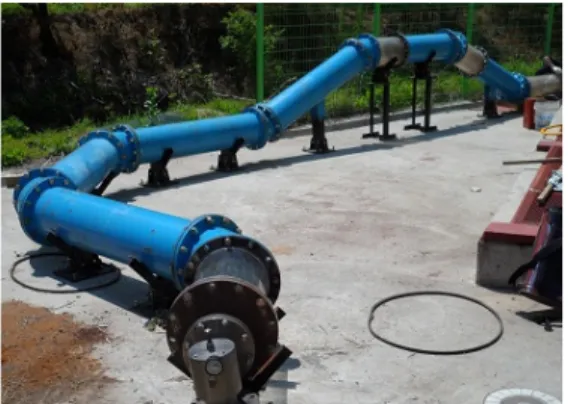
In order to validate the simulations, we tested a prototype in-pipe robot with screw drive in a 3-D pipeline. Figure 9 shows a prototype in-pipe robot with screw drive which is equipped with a water-jet nozzle as illustrated in Figure 1. Figure 10 shows a 3-D pipeline whose the total length is about 12m, internal radius is 150mm, which was constructed from steel pipes and four transparent pipes in acrylic for observation. Both the prototype in-pipe robot and the 3-D pipeline are manufactured to the identical specifications in the simulation (Table 1).
(a) CAD model of the in-pipe robot
(b) Assembled prototype in-pipe robot Figure 9: Prototype in-pipe robot with screw drive
Figure 10: 3-D pipeline for experiments
4.2 Experimental results
The prototype in-pipe robot moves forward and emits the water-jet at the same time inside the 3-D pipeline. As it is difficult to make a transparent curved pipe, the curved pipes were made of steel which is opaque consequently. Therefore the water-jet motion in the 3-D pipeline was only observed through the transparent straight pipes.
Figure 11 shows the consecutive images of the water-jet in the straight pipe. Herein, the water-jet is pointed out by a solid circle. Figure 12 shows the measured values of the water-jet interval at the longitudinal axis of the straight pipe. From the
experiments, the average of the water-jet intervals is 66mm that is similar to the result of simulation, approximately 65.9mm.
Figure 11: Consecutive water-jet images at a longitudinal axis of the straight pipe
Figure 12: Water-jet interval measured in one complete cleaning process
5. Discussion and Conclusion
The main contribution of this paper is the understanding of the water-jet cleaning motion of the in-pipe robot with screw drive inside the water pipes. The mathematical models of the water-jet in the two pipes were presented and the simulations were performed. Through the simulations we estimated the water-jet trajectory, the interval and the speed. Additionally the experiments have demonstrated that the simulations successfully estimate the water-jet motion inside the water pipes.
In the experiments, lots of factors which were not considered in the simulations and unpredictable interferences have an effect on the water-jet motion but the experimental results were very similar to the simulation results. In other words, the kinematic factors mainly determine the water-jet motion of the in-pipe robot in our experimental conditions (relatively short 3-D pipeline, flat inner surface of the pipes and so on).
In consequence of the simulations, in-pipe robot operators can understand the water-jet motion in a target water pipe and flexibly make a proper water-jet motion by changing the robot configurations, e.g. a tile angle of the wheels in rotor(α), a discharge angle of the water-jet(φ) and an angular velocity of the actuator, before a cleaning work.
Although the high pressure water-jet and the in-pipe robot with screw drive have been used to clean the water pipes in this study, those can be applied to different types of pipes such as gas, oil and slurry pipelines of plants.
Acknowledgments
This research was supported by the Ministry of Knowledge Economy (MKE, Republic of Korea), under the regional industrial technology development program (A000200452).
References
[1] Hyun-Dong Lee, “Renovation technologies in maintenance of water distribution systems”, Journal of the Korean Society of Environmental Engineers, vol. 29, no. 12, pp. 1297-1309, 2007.
[2] Chul-Ho Bae, Ju-Hwan Kim, Kyung-Jae Lee, Seong-Ho Hong, “Application of rehabilitation technologies of water mains in Korea”, Journal of the Korean Society of Water and Wastewater, vol. 20, no. 6, pp. 779-786, 2006.
[3] Atsushi Kakogawa and Shugen Ma, “Mobility of In-pipe robot with screw drive mechanism inside curved pipes”, Proceedings of the 2010 IEEE International Conference on Robotics and Biomimetics (ROBIO), pp. 1530-1535, 2010.
[4] Mihaita Horodinca, Ioan Doroftei, Emmanuel Mignon and Andre Preumont, “A simple architecture for in-pipe inspection robots”, Proceedings of the International Colloquium on Mobile and Autonomous Systems, pp. 61-64, 2002.
[5] Shigeo Hirose, Hidetaka Ohno, Takeo Mitsui and Kiichi Suyama, “Design of in-pipe inspection vehicles for φ25,φ50,φ150 pipes”, Proceedings of 1999 IEEE International Conference on Robotics & Automation, pp.
2309-2314, 1999.
[6] Iwao Hayashi, Nobuyuki Iwatsuki and Shigeru Iwashina, “The running characteristics of a screw-principle microrobot in a small bent pipe”, Proceeding of the Sixth International Symposium on Micro Machine and Human Science, pp. 225-228, 1995.
[7] S. Poozesh, M. Mehrandezh, H. Najjaran, and R. Paranjape, “Design and development of a smart vehicle for inspection of in-service water mains”, Proceedings of the Canadian Conference on Electrical and Computer Engineering, pp. 1203-1206, 2007.