Enhanced Multi-Channel Adaptive Noise Control Compensating Nonlinear Distortions
비선형 왜곡을 보상하는 향상된 다채널 적응 소음 제어
Oh Sang Kwon† (권오상†)
Department of Electrical and Electronics Engineering, The Cyber University of Korea (Received August 4, 2014; revised September 1, 2014; accepted October 31, 2014)
ABSTRACT: In fields of controlling acoustical noises, the overall adaptive control system is nonlinear due to the loudspeaker, amplifiers, converters, and microphones, etc. and the performance of noise control is decreased by the extent of nonlinearities, so an adaptive control system compensating nonlinear distortions is needed. In this paper, a new multi-channel adaptive noise controller was proposed, which was combined with the adaptive compensator to effectively linearize nonlinear distortions in the overall adaptive control system. Through computer simulations, the proposed adaptive compensator could linearize the nonlinear distortions and the proposed noise controller had better capability of controlling the noises than the conventional LMS controller.
Keywords: Adaptive noise control, Linearization, Nonlinear distortion.
PACS numbers: 43.50.Ki, 43.50.Hg, 43.50.Lj
초 록: 음향학적인 소음을 제어하는 영역에서는 스피커, 증폭기, 변환기, 그리고 마이크로폰 등에 의해서 전체 적응 제어 시스템이 비선형이므로 소음 제어 성능은 비선형성 정도에 의해서 결정된다. 따라서 비선형성 왜곡을 보상하는 적응 제어 시스템이 필요하며, 본 논문에서는 비선형성 왜곡을 효과적으로 선형화하는 적응 보상기와 결합한 새로운 다채널 적응 소음 제어기를 제안하였다. 모의실험을 통해 제안한 적응 보상기가 비선형왜곡을 선형화하고 기존의 LMS 제어기보다 소음을 감쇠하는데 월등함을 증명하였다.
핵심용어: 적응소음제어, 선형화, 비선형 왜곡
†Corresponding author: Oh Sang Kwon ([email protected]) Department of Electrical and Electronics Engineering, The Cyber University of Korea, 106 Bukchon-Ro, Jongno-Gu, Seoul 110-800, Republic of Korea
(Tel: 82-2-6361-1906, Fax: 82-2-6361-1800)
I. Introduction
The adaptive noise control of sound and vibration involves the introduction of a number of controlled secondary sources driven such that the field generated by these sources interferes destructively with the field caused by the original primary source. Simple acoustic problems such as fan noise in which the sound propagation is one dimensional can be effectively controlled using a simple single channel system. However, applications in which the sound field is spatially more complex, as for example in the case of adaptive control of propeller induced cabin
noise,[1] require a multi-channel approach. The multiple-error LMS algorithm has shown itself to be very effective and robust when used in these situations.[2,3] This algorithm, however, has a slow convergence speed and a correlated reference signal must be available.
In real environment of adaptively controlling the acoustical noises, the presence of a transfer function in the secondary path following the adaptive controller and/or in the error path, been shown to generally degrade the performance of the LMS algorithm. Also, the overall active control systems may be nonlinear due to the loudspeaker acting as the secondary source, including amplifiers, converters, and microphones acting as the sensor, etc. In this environment, the performance of adaptive noise control may be decreased
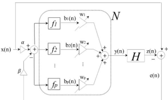
Fig. 1. Block diagram of the proposed single channel adaptive nonlinear compensator linearizing nonlinear distortions in the secondary path.
system compensating nonlinear distortions is needed.
In this paper, a robust multi-channel adaptive noise control system with a compensator of nonlinear distortion in the secondary path is presented. Thus, the new adaptive controller can make overall adaptive control systems linear and may have higher performance.
This paper is organized as follows. Section II provides a derivation of the proposed adaptive nonlinear compensator and Section III provides a derivation of the proposed adaptive noise controller. The experimental results are presented in Section IV, and concluding remarks are summarized in Section V.
II. The Adaptive Nonlinear Compensator
In terms of, the block diagram[4] of the proposed single-channel nonlinear compensator adaptively linearizing nonlinear distortions in the secondary path is shown as Fig.
1. The memory-less adaptive compensator, or pre-processor N is located in front of a nonlinear distortion generating system H. Here, H is assumed to be a delay-less system, which comprises of linear combination of P nonlinear functions representing overall nonlinear distortion systems.
The adaptive compensator is composed of the linear combination of the nonlinear functions and the relations between inputs and outputs are as follows.
where is the number of the used functions and
⋯ represents the nonlinear functions series and the Taylor series, the Fourier series etc. can be used for it. When the outputs of the nonlinear functions and the coefficients of the adaptive compensator can be defined as follows,
⋯, (2) with
⋯, (3)
where and are the weighting factors of the original reference signal and the feedback error signal, respectively and equal to small constants.
⋯. (4)
The optimum coefficient value of the compensator is given by minimizing the variance of the distortion and its compensation mechanism is produced as follows.
. (5)
III. The Proposed Multi-channel Adaptive Noise Controller
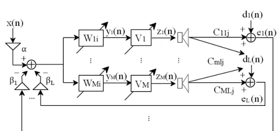
The block diagram of the proposed multi-channel adaptive control system is shown as Fig. 2.[3] In the figure, let the sampled input to the m-th actuator be obtained by filtering the weighted reference signal
and the weighted error signals using adaptive FIR controllers whose i-th coefficient at the n-th sample is
, so that
Fig. 2. Block diagram of the proposed multi-channel adaptive control system linearizing nonlinear distortions.
, (6)
where and are the weighting factors of the original reference signal and the l-th error sensor output respectively and determine the stability of the original reference signal and the l-th error signal, respectively. is the number of the coefficients for the adaptive FIR filters and is the number of the error sensors.
The outputs of the adaptive nonlinear compensators
are as follows.
, (7)
where is the number of the used functions and
⋯ represents the nonlinear functions series and the Taylor series, the Fourier series etc. can be used for it. Here, adaptive nonlinear compensators assume to sufficiently estimate the nonlinear distortions from speakers to error sensors.[4]
The sampled output of the l-th error sensor is , which is equal to the sum of the desired signal , due to the primary source alone, and outputs due to the actuators. Let the transfer function from the input of the m-th actuator to the output of the l-th sensor be modeled as a J-th order FIR filter, whose j-th coefficient is , so that
, (8)
∙
, (9)
(10)
Let the cost function at each error sensor be defined as
≈ , (11)
where ∙ denotes an expectation value. If the reference signal and the error signals are at least partly correlated with each , it is possible to reduce the value of by deriving the secondary sources. The total error may be a quadratic function of each of the filter coefficients and the optimal set of these coefficients required to minimize may thus be evaluated adaptively using gradient descent methods.
The gradient vector is evaluated as follows.
∇
, (12)
Fig. 3. Simulation environment for the proposed multi- channel active control system linearizing nonlinear distortion in a car.
In Eq.(12), is called “weighted filtered reference signal” and this sequence is the same as the one which would be obtained at the l-th sensor if the weighted reference signal and the weighted error signal, delayed by
samples, were applied to the m-th actuator.
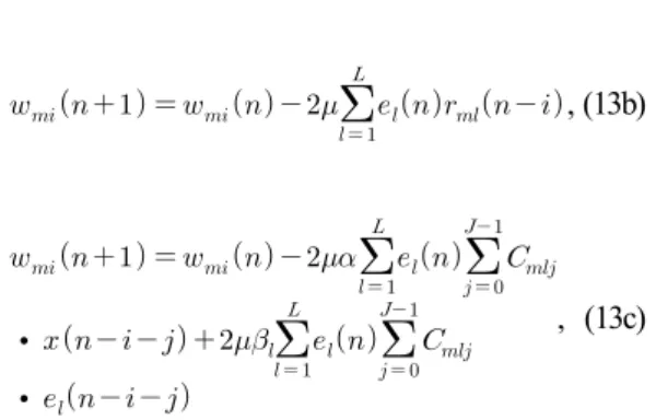
If each coefficient is now adjusted at every sample time by an amount proportional to the negative instantaneous value of the gradient, the filter coefficients adaptation mechanism is produced.
∇, (13a)
, (13b)
∙
∙
, (13c)
where is the convergence parameter that determines both adaptation speed and stability. For zero weighting factor of the original reference signal ( ), this corresponds exactly to the “Multi-channel Filtered-error LMS” algorithm and the values of is limited to . For all zero weighting factors of the error signals ( ), this corresponds exactly to the “Multi-channel filtered-x LMS”
algorithm,[2] and for a single speaker and single microphone system ( ), these are also reduced exactly to the
“Filtered-x LMS” algorithm.[5]
IV. Experimental Results
For simulations, an adaptive control of engine noises in a car with two speakers and two microphones was performed.
system linearizing nonlinear distortion in a car is shown as Fig. 3. Here, the overall adaptive control systems may be nonlinear due to the loudspeaker acting as the secondary source, including amplifiers, converters, and microphones acting as the sensor, etc. In this experiment, the nonlinear distortions are difficult to estimate, so the sigmoid function assume to exist in the secondary path as nonlinear distortion generating components.[4] The performance of adaptive noise control may be decreased by the extent of nonlinearities and an adaptive control system compensating nonlinear distortions is needed. Therefore, the overall controller consists of both adaptive linear filters controlling the noise and adaptive nonlinear filers compensating the nonlinear distortions. Thus, the overall adaptive control systems may be linear due to the nonlinear compensator, so the proposed adaptive controller can have higher performance. The engine ignition signal was picked up from engine control unit (ECU) component used as an original reference signal and error sensor outputs in a cabin were used as primary signals while the engine rotations per minutes (RPM) of car were changing, and both reference signal and primary signals were band-limited to 300 Hz.
The time length of data samples was twenty seconds by the sampling rate of 1000 Hz. And four impulse responses of the secondary path from speakers and microphones were
(A) Nonlinear compensator not used (B) Nonlinear compensator used
Fig. 4. Power density spectrum of engine noises before control [(a) dashed line], after conventional LMS control [(b) dotted line], and proposed control [(c) solid line] on the position of driver’s seat.
(A) Nonlinear compensator not used (B) Nonlinear compensator used
Fig. 5. Power density spectrum of engine noises before control [(a) dashed line], after conventional LMS control [(b) dotted line], and proposed control [(c) solid line] on the position of assistant driver’s seat.
estimated using the maximum length sequence.[6] And the number of adaptive filter coefficients and the impulse res- ponse coefficients used were 64 and 64, respectively. And it is assumed that the effects from speakers to microphones are equal. The value of is determined under the condition of all zero weighting factors of the error signals ( ) and similarly the equivalent values of are determined under the condition of zero weighting factor of the original reference signal ( ). In the experiment, ,
, and were used.
The adaptive nonlinear filters are pre-distorters and function as inverse filters to estimate nonlinear distortions[7]
Figs. 4 and 5 represent the results for the adaptive control
of engine noises in the driver seat position and assistant driver seat position seat, for both the conventional LMS controller and the proposed controller, in the frequency domain. The engine RPM is ranged from 3000 to 5000 rpm and their dominant noise components (C2) are distributed between 100 Hz to 166.7 Hz. From the figures, it is verified that the performances of the proposed controller with adaptive nonlinear compensator are better than those without the compensator. In the figures, (a), (b), and (c) represent the primary noises before control, after the conventional LMS control, and after the proposed control, respectively.
From the figures, it is verified that in both case of driver
controllers can control the noises with the adaptive nonlinear compensator better than without the compensator, and the proposed controller can control the engine noise better than the conventional LMS controller by 15 dB for pure tone and globally 10 dB. This is because the adaptive nonlinear compensators may linearize the secondary path, so the adaptive linear filter can control noises better.
V. Conclusions
In this paper, a new multi-channel adaptive noise controller was proposed to linearize nonlinear distortions in the secondary paths and was applied for attenuating the noises. The proposed adaptive controller was based on the combination of both feedforward and feedback control system in order to increase the performance robustness with very small complexity increment. In the proposed controller, new generated reference signals comprised of weighted sum of an original reference signal and error signals, were used as inputs to the controller. These new signals may depend on the properties of both an original reference signal and feedback error signals according to the weighting factors. Through analytical analysis and computer simulations, the proposed controller may have better capability of controlling the noises than the conventional LMS controller with nearly equivalent complexity of computation.
References
1. S. J. Elliott, P. A. Nelson, I. M. Stothers, and C. C. Boucher,
“In-flight experiments on the active control of propeller- induced cabin noise,” J. Sound and Vib, 219-238 (1990).
2. S. J. Elliott, I. M. Stothers, P. A. Nelson, “A multiple error LMS algorithm and its application to the active control of sound and vibration,” IEEE Trans. 35, 1423-1434 (1987).
3. O. S. Kwon and I. W. Cha, “Multi-channel optional summed algorithm for active noise control,” IET ELECTRONICS LETTERS 34, 1559-1560 (1998).
4. O. S. Kwon, “Hybrid adaptive volterra filter robust to nonlinear distortion” (in Korean), J. Acoust. Soc. Kr. 27,
(Englewood Cliffs, New Jersey, 1985), pp. 270-294.
6. D. D. Rife, “Modulation transfer function measurement with maximum-length sequences,” J. Audio Eng. 40, 779-789 (1992).
7. O. S. Kwon, “Robust active noise controller with hybrid adaptive nonlinear compensator” (in Korean), J. Acoust.
Soc. Kr. 28, 16-22 (2009).
Profile
▸Oh Sang Kwon (권오상)
He received the B.S., the M.S. and the Ph.D degrees in electronics engineering from Department of Electronics, Yonsei University, Seoul, Korea, in 1992, 1994 and 1999, respectively. In Feburary 1994, he joined CSPR (Center for Signal Processing Research) in Yonsei University. From 1999 to 2003, he had been with Samsung Advanced Institute of Technology, Suwon, Korea, where he was working on communication signal processing and modem. He is now a professor in The Cyber University of Korea. His interests include acoustic signal processing, multimedia, and communication signal processing.
![Fig. 5. Power density spectrum of engine noises before control [(a) dashed line], after conventional LMS control [(b) dotted line], and proposed control [(c) solid line] on the position of assistant driver’s seat.](https://thumb-ap.123doks.com/thumbv2/123dokinfo/4745509.270008/5.892.139.755.820.1072/density-spectrum-control-conventional-control-proposed-position-assistant.webp)
