SNCM616 합금강을 이용한 진원도와 치수정밀도 분석 Roundness and Dimensional Accuracy
Analysis using SNCM616 Alloy Still
최철웅
1
, 김진수2
, 신미정2*
Chul-Woong Choi
1, Jin-Su Kim
2, Mi-Jung Shin
2*<Abstract>
In this study, it was aimed to find the optimal cutting conditions by measuring and analyzing the dimensional accuracy of SNCM 616 alloy steel, which is commonly used in industry, by precision hole machining using Ø25 mm and 8-blade reamer in CNC-HBM to be. As a result of the roundness and dimensional accuracy, it was found that the spindle speed had a significant effect on the dimensional tolerance value.
Optimum cutting conditions are spindle speed 25 rpm and feed rate 20 mm / min.
Keywords : dimensional accuracy, Reamer Machining, Boring Machining
1 주저자 대명하이텍,과장
2 2저자 한국폴리텍7대학 컴퓨터응용기계과 3* 2저자,교신저자 한국폴리텍7대학 컴퓨터응용기계과
E-mail : [email protected]
1 Dea-Myoung HITEC
2 College of Computer Application Mechanical, Korea Polytechnic UNIV
3* College of Computer Application Mechanical, Korea
Polytechnic UNIV
절삭가공에서 가공 정밀도에 직접적 영향을 미 치는 주요 인자로는 절삭속도, 이송속도, 절삭깊 이 등이 있다. 일반적으로 이송속도를 증가시키면 형상 오차가 커지게 되고 주축의 회전수를 증가 시키면, 공구 수명이 짧아지는 결과를 초래한 다.[1-8]
최근의 추세는 다품종 소량생산의 확대와 고 정도제품에 대한 수요 증가에 의해 전문가공 및 정밀가공의 필요성이 더욱 커지고 있다. 이에 따 라 공작물의 정밀 측정 또한 중요하다.[9]
특히 금속을 가공함에 있어서 드릴링, 리밍, 보 링, 탭핑 등과 같은 홀(Hole) 작업들은 모든 가공 공정들의 1/3 가량을 구성한다고하며 거의 모든 가공공정에 포함될 수밖에 없는 공정으로 생산성 에도 많은 영향을 주고 있다.[10,11]
홀(Hole)가공방법 중에서 드릴가공의 이상적인 결과는 원하는 위치에 원하는 치수의 구멍이 수직 으로 뚫리는 것이다. 그러나 실제는 드릴 선단부 의 비대칭성, 회전축의 편심, 횡방향 진동 등에 의하여 가공정밀도가 떨어지지만 그럼에도 불구하 고 드릴가공은 구멍을 내기 위한 주요 기계작업이 다. 모든 금속의 절삭 작업 중 드릴가공은 전체의 30%를 차지하고 있을 만큼 매우 중요한 작업이 다. 특히 트위스트 드릴은 원동형의 구멍과 기존 구멍의 크기를 넓히는데 가장 폭넓게 사용되고 있 다.[12,13]
최근 절삭가공의 추세는 높은 압력으로 다듬 질양이 많은 공작을 한 후 연삭을 하지 않고 보링, 리밍과 같은 전가공에서 곧바로 호닝으로 정밀 다듬질을 실시하는 방법이 성행하고 있 다.[14]
고 경도강의 구멍 가공을 고속으로 가공시 진동(Vibration)에 의해 흔들림 또는 마찰열 등
다.[6,9,15]
본 연구는 산업현장에서 터빈로타(Rotor), 크랭 크축, 피스톤핀, 방탄강판 등에 일반적으로 사용되 는 SNCM 616 합금강을 CNC HBM(Horizontal Boring Machine)에서 Ø25 mm, 길이가 268 mm 리머공구를 사용하여 홀(Holl)을 정밀하게 가공 후 진원도 및 치수정밀도를 측정하고 분 석하여 최적의 절삭조건을 제시하는데 목적이 있다.
2. 실험장치 및 재료
2.1
실험장치본 실험에 사용한 가공장비는 HBM으로 Forest Siret에서 생산한 840C 모델이며, 가공방법은 Fig.
1에 도시하였으며, Fig. 2는 실험 가공장비이며, 세부 사양은 Table 1에 나타내었다.
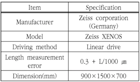
진원도 측정은 자이스(Zeiss) 브릿기 타입의 3 차원 측정기를 이용하여 자동 측정을 실시하였다.
진원도 측정을 위한 측정 장비는 측정범위가 1 m
3에 가까운 900×1500×700 ㎜ 이고 Fig. 3에 나 타내었으며, 세부사양은 Table 2와 같다.
치수 정밀도를 측정하기 위한 장비는 Fig. 4이
고 사양은 Hexagon사의 CNC 정밀 비접촉 측정
용 기기인 SVM 4030 DCC Standard이며, 3축
CNC 제어시스템으로 비접촉 CNC 시스템에서 컴
퓨터로 측정하였다. 치수측정 장비의 세부사양은
Table 3과 같고 가공된 시편의 치수 정밀도 측정
위치는 Fig. 5에 나타내었다.
Fig. 1 Schematic diagram of experimental
Fig. 4 Dimension-measuring device
Fig. 2 HBM Machining Equipment Fig. 5 Measuring position
Fig. 3 3D measuring metrology
Item Specification
Manufacturer Forest Siret
Model 840C
Table size [mm] 1600×2000 Main spindle speed [rpm] 630
Main spindle taper BT No. 40
Stroke [mm]
X-axis 8000
Y-axis 3200
Z-axis 1050
Z-axis 800
Table 1. Machining Center specification
경드릴(Carbide twist drill)과 외경이 각각 ∅ 24.5, ∅25.0 mm의 고속도강(SKH51) 리머를 사 용하였다. Fig. 5은 이지원사의 드릴과 유림정밀사 의 리머를 사용하였고 Table 3, 4은 드릴공구와 리머공구의 형상과 치수를 나타내었다.
(a) Carbide Twist Drill
(b) Reamer (SKH51)
Fig. 6 Twist Drill and Reamer tools
Manufacturer Zeiss corporation(Germany)
Model Zeiss XENOS
Driving method Linear drive Length measurement
error 0.3 + L/1000 ㎛ Dimension(mm) 900×1500×700
Item Specification
Machine type SVM 4030 DCC Standard Strokes(mm) 400×300×200
External
dimension(mm) 866×903×1015
Weight(kg) 280
Max.Part weight 16Kg
Accuracy XY axis 3.0+L/150
Z axis 6+L/150
Speed 80mm/s
Scale Resolution 1㎛
CCD High-precision industrial color CCD
Light ource
Rim light
- Green LED, luminance controllde by software - White LED, luminance controllde by software Optical system Manual zoom lens
Software VMS 6.0
Motion control High-precision control card Working
environment
20±2°C, Humidity 45%∼75%
Power source
220v±10% 50Hz, Reliable grumding is required
(less than 4Ω)
Table 3. Specifications of the non-contact measuring instrument
Carbide Twist Drill
material Carbide-TIN Coating
D2 d L1 L2 angle
24 32 170 110 140。
Table 4. Dimension and shape of drill(mm)
3. 실험방법 및 고찰
3.1
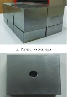
실험방법연구 실험을 위해 준비된 SNCM616 합금강의 화학성분은 Table 6과 같다. 150×150×50 mm 의 소재 20개를 준비하였으며, 소재의 가공 전⋅후 의 시편은 Fig. 7과 같다. 먼저 소재를 Fig. 1과 같 이 고정하고 ∅24.0 드릴을 장착하여 Fig. 8과 같이 소재를 관통하여 가공하였다. 가공시 수용성 절삭 유를 사용하였으며, 절삭유의 혼합비율은 20 : 1 로 희석하였고 절삭유 타입은 Table 7과 같다. 드 릴링 작업 후 ∅24.5 리머를 이용하여 홀(Hole) 정밀가공 후 ∅25.0 리머로 한번 더 정밀가공을 한 후에 진원도와 치수 정밀도를 측정하여 분석하 였다. 절삭가공 조건은 스핀들 속도는 20 rpm에 서 35 rpm, 이송속도는 15 mm/min에서 30 mm/min 으로 변경하였으며, 실험조건은 Table 8 과 같이 결정하였다.
본 연구는∅25.0 리머를 사용하여 홀(Hole)가공 후 Fig. 5와 같이 진원도와 치수정밀도 공차를 측 정하였다.
3.2
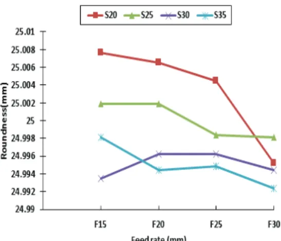
실험고찰길이 268 mm의 긴 리머공구를 이용하여 가 공 후 진원도를 측정하여 분석한 결과는 Fig. 9 와 같다. Fig. 9에서 전체 스핀들속도 영역 중에 서 20 rpm과 35 rpm에서 진원도 오차가 크게 나타났다.
또한 전체 스핀들 속도 영역 중에서 30 rpm에 서 일정한 값이 나타났지만 25 rpm에서 진원도 24.9984로 비교적 안정적인 값이 나타남을 알 수 있었다. Fig. 9에서 치수 차이가 나타나는 이유는 리머 절삭공구의 길이가 길어 절삭저항에 의한 떨 림이 발생한 것으로 생각되며, 이송속도보다는 스 핀들 속도에 따라 진원도에 미치는 영향이 크게 나타남을 알 수 있었다.
Fig. 10에서 치수정밀도를 분석하면 스핀들속도 25 rpm 과 이송속도 20 mm/min 에서 치수가 Ø25.02 로 치수공차가 가장 정밀하게 나타났고 스핀들속도 30 rpm과 이송속도 30 mm/min 일 때 Ø25.036 으로 치수정밀도 오차가 가장 크게 나타남을 알 수 있었다.
이송속도의 평균값을 비교 분석하면 이송속도보 다 스핀들속도가 치수공차에 영향을 많이 미치는 것으로 나타났다.
진원도와 치수정밀도를 측정한 결과 치수공차의 경우 일반적인 가공에서 스핀들속도가 높고 이송 속도가 적을 때 진원도 및 치수정밀도가 뛰어난 것으로 나타났다. 하지만 Ø25 의 긴 리머 공구로 SNCM 616 합금강을 구멍가공을 할 때 스핀들속 도가 높은 30 rpm 에서 치수공차가 많이 발생되 며, 그것은 스핀들속도가 높을수록 공구와 모재간 의 마찰 및 진동이 발생하여 치수정밀도가 나쁘게 나타났다고 판단된다. 또한 이송속도 30 mm/min 에서 치수 정밀도가 나쁜 것은 스핀들속도에 비하 여 이송속도가 높아 리머에 과다한 절삭력이 전달
MT.Shank SP FL Chucking Reamermaterial SKH51
number of flutes 8
D1 L1 L2
24.5, 25.0 68 268
L2 L1
D1 Table 5. Dimension and shape of reamer(mm)
mm/min 임을 알 수 있었다.
Element New Code Old Code SNCM 616 (%) SNCM 26 (%)
C 0.13∼0.20
Si 0.15∼0.35
Mn 0.80∼1.20
P 0.30 or less
S 0.30 or less
Ni 2.80∼3.20
Cr 1.40∼1.80
Mo 0.40∼0.60
Table 6. Chemical composition of SNCM 616 (KS D 3709)
Product name Superedge 47K (A) Product code 465473-KR01
Manufacturer Castrol
Producer Bipi korea
GHS Classification
Material/uses of mixtures sharing metals-water soluble(5%) Table 7. Type of water soluble cutting oil
Workpiece
Spindle speed (rpm)
Feed rate (mm/min)
Depth of cut (mm)
SNCM 616 20 25 30 35
15 20 25 30
50 Table 8. Experimental conditions of cutting process
(a) Previous experiments
(b) After the experiment
Fig. 7 Photograph of SNCM 616 alloy steel
Fig. 8 Hole position and size
4. 결 론
터빈 Rotor, 크랭크축, 프로펠러축, 피스톤핀, 방탄강판 등에 사용되는 재료인 SNCM 616 합금 강을 CNC HBM에서 고속도강 재질의 Ø25 mm, 길이 268 mm 리머로 구멍가공을 하였을 때 스 핀들속도와 이송속도의 변화를 통해 진원도와 치
수정밀도 특성은 다음과 같은 결론을 보였다.
1. 진원도를 측정한 결과 스핀들속도 영역중에 서 30 rpm에서 일정한 값이, 25 rpm 에서 는 안정적인 값이 나타났다. 가장 정밀한 진 원도 값 ∅24.9984 mm의 절삭조건은 스핀 들속도 25 rpm, 이송속도 25 mm/min 임 을 알 수 있었다.
2. 치수정밀도를 측정한 결과 치수가 가장 정밀 한 Ø25.02 mm의 절삭가공 조건은 스핀들 속도 25 rpm, 이송속도 20 mm/min 임을 알 수 있었다.
3. 진원도 및 치수정밀도에서 이송속도보다는 스핀들속도가 진원도 및 치수정밀도에 미치 는 영향이 큰 것을 알 수 있었다.
4. 고속도강 Ø25 mm, 길이 268 mm 리머로 SNCM 616 합금강을 구멍 가공하였을 때 이송속도 보다는 스핀들속도가 홀(Hole)의 치수공차에 미치는 영향이 크며 최적의 절 삭조건은 스핀들속도 25 rpm, 이송속도 20 mm/min 임을 알 수 있었다.
참고문헌
![Table size [mm] 1600×2000 Main spindle speed [rpm] 630](https://thumb-ap.123doks.com/thumbv2/123dokinfo/4854292.528494/3.876.457.753.799.1027/table-size-mm-main-spindle-speed-rpm.webp)