좌굴성능을 고려한 평판 좌굴문제의 위상설계최적화
이 승 욱1․안 승 호1․조 선 호1†
1서울대학교 아이소-지오메트릭 최적설계 창의연구단 및 조선해양공학과
Topology Design Optimization of Plate Buckling Problems Considering Buckling Performance
Seung-Wook Lee1, Seung-Ho Ahn1 and Seonho Cho1†
1National Creative Research Initiatives(NCRI) Center for Isogeometric Optimal Design Department of Naval Architecture and Ocean Engineering.
Seoul National University, Seoul, 08826, Korea
Abstract
In this paper we perform a linearized buckling analysis using the Kirchhoff plate theory and the von Karman nonlinear strain-displacement relation. Design sensitivity analysis(DSA) expressions for plane elasticity and buckling problems are derived with respect to Young’s modulus and thickness. Using the design sensitivity, we can formulate the topology optimization method for minimizing the compliance and maximizing eigenvalues. We develop a topology optimization method applicable to plate buckling problems using the prestress for buckling analysis. Since the prestress is needed to assemble the stress matrix for buckling problem using the von Karman nonlinear strain, we introduced out-of-plane motion. The design variables are parameterized into normalized bulk material densities. The objective functions are the minimum compliance and the maximum eigenvalues and the constraint is the allowable volume. Through several numerical examples, the developed DSA method is verified to yield very accurate sensitivity results compared with the finite difference ones and the topology optimization yields physically meaningful results.
Keywords : design sensitivity analysis, eigenvalue, buckling analysis, prestress, topology optimization
†Corresponding author:
Tel: +82-2-880-7322; E-mail: [email protected] Received June 26 2014; Revised March 25 2015;
Accepted June 19 2015
Ⓒ 2015 by Computational Structural Engineering Institute of Korea
This is an Open-Access article distributed under the terms of the Creative Commons Attribution Non-Commercial License(http://creativecommons.
org/licenses/by-nc/3.0) which permits unrestricted non-commercial use, distribution, and reproduction in any medium, provided the original work is properly cited.
1. Introduction
The subject of this paper is topology optimization of a buckling problem. A topology optimization method helps designers find a suitable material layout for the required performances. Bendsoe and Kikuchi’s(1988) homogenization based approach was introduced for the topology optimization, and many linear material behaviors and geometrically nonlinear topology optimization methods have been developed (Jung and Cho, 2003). Since the topology optimization necessarily involves many design variables, the design sensitivity analysis(DSA) of performance measure with respect to the design variables should be deter-
mined in a very efficient way. A continuum based DSA approach, which can handle several types of design variables, was developed(Haug et al., 2003).
In this paper, a continuum method for the non-shape problems like material property is considered. We develop an efficient DSA method for both the maximization of critical load and minimization of compliance.
Buckling may occur as a structural response when the in-plane directional membrane force is applied to the structures. The motion of interest occurs out-of-plane direction because the out-of- plane directional buckling motion occurs faster than the in-plane directional buckling motion. The pres-
Fig. 2 Elastic body in space tress to be added to the structural forces is one of
the forces in the plate. An initial stress matrix is added to the original matrix equation of the structure and consists the buckling equation(Cook et al., 1989). We apply the von Karman strain-displacement relation(Irving et al., 1985) to the original equation to derive the plate buckling equation. The plate buckling topology optimization problems are formu- lated using the derived plate buckling equation.
Finally, the plate buckling topology design optimi- zation problem is performed in several cases.
2. Plate Buckling Problems
The plate buckling governing equation is derived using the von Karman strain- displacement relation and kirchoff plate theory. Next, we can obtain the plate buckling equation as the following:
∇
(1)where ∇≡
and w is the ben- ding deflection. , , are the forces in the ,, direction measured per unit length shown in Fig. 1 respectively.
Fig. 1 External force component
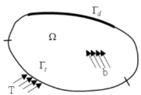
Consider a simple built-up structure with domain
shown in Fig. 2. The boundary of is composed of where the displacement is prescribed and
where traction t is the prescribed boundary.
The weak formulation of the fourth order diffe- rential Eq. (1) can be obtained by multiplying the virtual bending deflection with it, and integra- ting the equation over the domain . We obtain
Eq. (2) through the integration by part
∇∇
(2)
where is the flexural rigidity and is the Critical load factor. represents the bending moment, and represents the transverse shear force. The space of kinematically admissible field is defined as a set of displacement field. The space for the trial solution is defined as
∈
(3)Also, space for the virtual displacement field is defined as
∈
(4)where is the number of elements within the built up structure and ⊔⊔ ⋯ ⊔ is the essential boundary where the displacement is prescribed. By definition, Eq. (4) satisfies for every ∈
… that belongs to the space of kinema- tically admissible fields. Due to the above boundary conditions, boundary integrals of Eq. (2) vanish, and variational equation Eq. (2) can be rewritten using bilinear forms as
∀∈ (5) The bilinear forms are represented as
∇∇
(6)and
(7)3. Design Sensitivity Analysis of Plate Buckling Problems
Eigenvalue problems for buckling of elastic systems are described by a variational equation form
∀∈ (8)where satisfies the homogeneous boundary condition and belongs to the space of kinematically admissible displacements. The bilinear form
on the right side of Eq. (8) represents geometric effects in buckling problems. A variation of Eq. (8) about the design variable to calculate the design sensitivity is written as′
′
′
′
′
′
∀∈ (9)where is involved in the variational space, so can be written as . Then, we obtain
′ ′
′ ′′ ′ (10)
Design sensitivity of critical buckling load factor
is written as
′
′ ′ ′′ ′
(11)
′ ′ ≡
(12)Since virtual displacement is involved in varia- tional space, Eq. (11) is rewritten as
≡ ′
′ ′′
(13)
4. Formulation of Topology Design Optimization
The objective of the topology optimization method is to find an optimal material distribution that minimizes objective functions and is subject to constraints. The material distribution can be repre- sented using a normalized bulk material density function that has a continuous variation from zero to one, taking the value of one for solid material and zero for void. Bulk material density of each element is associated with Young’s modulus and is written as
(14)
≤ ≤ (15)
where , is the Young’s modulus of the original material. is a penalty parameter used to enforce a concentrated distribution of material.
4.1 Topology Optimization of Compliance
A topology design optimization without the critical buckling load problem is stated as
Minimize
(16)
Subject to
≤ (17)where is the compliance, is the body force intensity, is the traction, is the Displacement field, is the structural domain, is the allowance material volume and is the bulk material density.
Fig. 3 Distributive axial compression applied plate The sensitivity of design variable for the finite
element method is obtained by the variation of Eq.
(16) which is written as
(18)The total volume of structure is calculated by design variable . The constraint is expressed as
≡
≤ (19)
where is the constraint, is the material density and is the volume. We use the Modified Method of Feasible Direction(MMFD) to find the optimal design and MMFD is based on the gradient for the design variables. We need the sensitivity of objective function and the sensitivity of constraint. The sensitivity of constraint is obtained by
≡ (20)
4.2 Topology Optimization for Buckling
We formulate the topology optimization conside- ring the critical buckling load. If the compliance is considered only in optimization problem, only the stiffness of the structure can be hardened. Eq. (21) can be obtained by dividing Eq. (16) by the critical buckling load term.
(21)
Objective function can express both objectives that minimize the compliance and maximize the critical buckling load. We use the allowance material volume as the constraint. The design sensitivity of objective function is written as
(22)
Using the sensitivities, critical buckling load factor, and compliance, Eq. (22) can be computed.
5. Numerical Examples
5.1 DSA Verification
The purpose of this example is to verify the DSA method for the critical buckling load. We have two results in this numerical example of DSA. The first example is to verify the DSA of the critical buckling load with respect to Young’s modulus and the second example is to verify the DSA of critical buckling load with respect to thickness. The DSA method for the critical buckling load is verified and the buckling mode is made by the axial load and the shear direction load respectively. We use the Kirchhoff plate element to analyze the structure model and use the prestress to calculate the out-of-plane buckling load factor through the plane analysis. We obtain the DSA for critical buckling load applied to these two different type loads, the axial compress force and the shear force.
5.1.1 DSA of Critical Buckling under Axial Comp- ression Force
Consider a square plate whose aspect ratio is 4 under the distribute loading condition as shown in Fig. 3. The rectangular plate is discretized by 16×4 elements. The rectangular plate has a height of 40m, widthof 10m and a plate thickness of 0.01m.
A distributive axial compress loading 1N/m is applied along the right and left sides. Young’s modulus is 209×109(N/m2). Poison’s ratio is 0.3. Design variables are relative density and thickness for each element. Performance measure is the critical buckling load.
The analytical design sensitivity of the critical
Design
Variable ∆
∆
Accuracy
(%) 45 4.15350E+04 4.15268E+04 100.0196 46 3.07400E+04 3.07254E+04 100.0472 47 1.33736E+04 1.33873E+04 99.89730 48 5.56600E+04 5.56554E+04 100.0081 49 5.74150E+04 5.73722E+04 100.0744 50 1.59256E+04 1.59127E+04 100.0812 51 2.94062E+04 2.93863E+04 100.0676 64 5.64241E+04 5.63909E+04 100.0589
Table 3 Comparison of design sensitivity
Exact solution Numerical solution
Accuracy (%) Critical
buckling load 1.055E+04 1.078E+04 102.2243 Table 4 Comparison of the critical buckling load under
shear force buckling load factor with respect to Young’s modulus
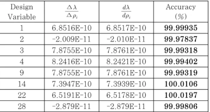
is compared with the finite difference sensitivity. In Table 1, design sensitivity of the critical buckling load factor in each nodes with respect to Young’s modulus of each element is compared. We compare the results of analytical sensitivity denoted as
with an identical result denoted as ∆∆. We compare the exact solution with numerical solution for critical buckling load. They show good agreement shown in Table 2.
Exact solution Numerical solution
Accuracy (%) Critical
buckling load 7.55584E+03 7.5452E+03 99.856 Table 1 Comparison of critical buckling load
Design
Variable ∆
∆
Accuracy
(%)
1 6.8516E-10 6.8517E-10 99.99935
2 -2.009E-11 -2.010E-11 99.97837
3 7.8755E-10 7.8761E-10 99.99318
4 8.2416E-10 8.2421E-10 99.99402
9 7.8755E-10 7.8761E-10 99.99319
14 7.3947E-10 7.3939E-10 100.0106 22 6.5191E-10 6.5178E-10 100.0197 28 -2.879E-11 -2.879E-11 99.99806
Table 2 Comparison of design sensitivity
We use the same way to verify the sizing sensitivity analysis results. The analytical design sensitivity of the critical buckling load with respect to thickness is compared with the finite difference sensitivity. In Table 3, the critical buckling load factor design sensitivity of each node with respect to thickness of each element is compared. We compare the results of analytical sensitivity and the identical
result. They show excellent agreement shown in Table 3.
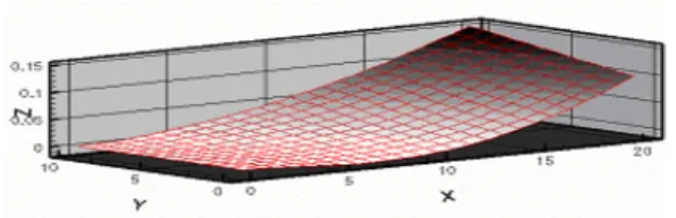
When the axial distributive compression force is applied on the plate, the plate is deformed in the out-of-plane direction. The buckling mode shape in the out-of-plane direction is shown in Fig. 4.
Fig. 4 Mode shape of axial distributive force applied
5.1.2 DSA of the Critical Buckling Applied the Shear Force
Consider the same model shown in Fig. 5. The rectangular plate is discretized by 16×4 elements.
The rectangular plate has a height of 40m, width of 10m and plate thickness of 0.01m. A distributive shear loading, 1N/m is applied along the edges.
Design variables are the relative density for each element. Performance measure is the critical buckling load.
Fig. 5 Distributive shear loading applied plate
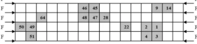
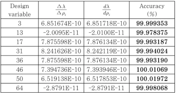
The analytical design sensitivity of the critical buckling load factor with respect to the relative density for each element is compared with the finite difference sensitivity. In Table 4, design sensitivity
of the critical buckling load factor in each nodes with respect to Young’s modulus of each element is compared. We compare the results of analytical sensitivity with an identical result. We compare the exact solution with numerical solution for critical buckling load. They show excellent agreement shown in Table 5.
Design
variable ∆
∆
Accuracy
(%) 3 6.851674E-10 6.851718E-10 99.999353 13 -2.0095E-11 -2.0100E-11 99.978375 17 7.875598E-10 7.876134E-10 99.993187 31 8.241626E-10 8.242119E-10 99.994024 36 7.875598E-10 7.876134E-10 99.993190 46 7.394736E-10 7.393946E-10 100.01069 50 6.519138E-10 6.517853E-10 100.01972 64 -2.8791E-11 -2.8791E-11 99.998068 Table 5 Comparison of design sensitivity for young’s
modulus
We use the same way to verify the sizing sensitivity analysis result. The analytical design sensitivity of the critical buckling load with respect to thickness is compared with the finite difference sensitivity. In Table 3, the critical buckling load factor design sensitivity of each node with respect to thickness of each element is compared. We compare the results of the analytical sensitivity and an identical result. They show excellent agreement shown in Table 6.
Design
variable ∆
∆
Accuracy
(%) 3 5.39079E+04 5.39500E+04 99.922040 13 1.89282E+03 1.89468E+03 99.901825 17 5.53565E+04 5.52252E+04 100.23774 31 9.96608E+04 9.95562E+04 100.10505 36 5.44183E+04 5.43790E+04 100.07223 46 1.36546E+04 1.36098E+04 100.32954 50 3.66279E+03 3.65487E+03 100.21656 64 3.68065E+04 3.66810E+04 100.34209 Table 6 Comparison of design sensitivity of thickness
When the shear distributive force is appliedto the plate, the plate is deformed in the out-of-plane direction. The buckling mode shape in the out-of- plane direction is shown in Fig. 6.
Fig. 6 Mode shape of distributed shear force applied
5.2 Topology Optimization
5.2.1 Topology optimization Applied the Axial Compression Force
The cantilever model subjected to a distributive axial compression is shown in Fig. 7. The optimi- zation result without considering the critical buckling load is also shown in Fig. 8 and the buckling mode shape is shown in Fig. 9. The critical buckling load factor is the value to multiply to the initial loading.
In this example the critical buckling load factor is 0.392977.
Fig. 7 Cantilever model specification under axial compression
Fig. 8 Optimal shape without considering buckling
Fig. 9 Buckling mode without considering buckling
The topology optimization results considering the critical buckling load is shown in Fig. 10 and the buckling mode shape is shown in Fig. 11. In this case, the critical buckling load factor is 0.534326.
The critical buckling load factor increased 36% than the previous result. We can modify the layout performance of the critical buckling load.
Fig. 10 Optimal shape with considering buckling
Fig. 11 Buckling mode with considering buckling
5.2.2 Topology optimization under shear force The cantilever model subjected to a distributed shear force is shown in Fig. 12. The final material distribution after the topology optimization result except for considering the critical buckling load is also shown in Fig. 13 and the buckling mode shape is shown in Fig. 14. The critical buckling load factor is 2.401125.
Fig. 12 Cantilever model specification under shear force
Fig. 13 Optimal shape without considering buckling
Fig. 14 Buckling mode shape without considering buckling
The topology optimization results considering the critical buckling load is shown in Fig. 15 and the buckling mode shape is shown in Fig. 16. The critical buckling load factor is 2.727772 in this case. The critical buckling load factor increased 14% than the previous result. We can modify the layout performance of the critical buckling load.
Fig. 15 Optimal shape with considering buckling
Fig. 16 Buckling mode shape with considering buckling
6. Conclusion
We derive the plate buckling equation including the out-of-plane direction buckling motion. Based on this equation, we derive a weak formulation for plate buckling problems and a continuum-based DSA method using a direct differentiation for eigenvalue design sensitivity approach in continuum form. Also, a topology design optimization method for plate buckling problems using the Kirchhoff plate theory is developed using the direct DSA method. For the topology optimization, the displacement of the buckling motion is calculated. The design variables are parameterized using bulk material densities.
Through several numerical examples, we verify the accuracy of the analytical DSA method by comparing the finite difference sensitivity. The analytical DSA method yields very accurate sensitivity results compared with those of the central finite difference method. Also the topology optimization yields physically meaningful results. It could result in different optimal shapes depending on the critical buckling load and force applied. The topology optimization results considering the critical buckling load factor significantly increase the critical buckling load factor.
Acknowledgement
This work was supported by the National Research Foundation of Korea(NRF) grant funded by the Korea government(No.2010-0018282). The support is grate- fully acknowledged. The authors would also like to thank Ms. Inyoung Cho at Korea University for editing assistance.
References
Bendsøe, M.P., Kikuchi, N. (1988) Generating Optimal Topologies in Structural Design using a Homogenization Method, Comput. Methods Appl.
Mech. & Eng., 71(2), pp.197~224.
Cook, R.D., Malkus, D.S., Plesha, M.E. (1989) Concepts and Applications of Finite Element Analysis, John Wiley & Sons, Inc. p.784.
Haug, E.J., Choi, K.K., Komkov, V. (1986) Design Sensitivity Analysis of Structural System, Academic Press : New York, NY, p.38.
Ha, Y.D., Kwak, J.H., Cho, S. (2002) Topology Optimization of Structural Frame in Human Powered Vessel, Proceeding of the Annual Autumn Meeting-SNAK.
Irving, H.S., Dym, C.L. (1985) Energy and Finite Element Method in Structural Mechanics, Hemisphere Publishing Company, p.776.
Jung, H.S. (2003) Design Sensitivity Analysis and Topology Optimization of Displacement-loaded Nonlinear Structures, Comput. Methods in Appl.
Mech. & Eng., pp.2539~2553.
Kim, M.G., Kim, J.H., Cho, S. (2010) Topology Design Optimization of Heat Conduction Problems using Adjoint Sensitivity Analysis Method, J. Comput.
Struct. Eng. Inst. Korea, 23(6), pp.683~691.
Malvern, L.E. (1969) Introduction to The Mechanics of a Continuous Medium, Prentice Hall Inc., New Jersey. p.711.
Reddy, J.N. (1993) An Introduction to The Finite Element Method, Mcgraw-Hill Book Company, p.896.
Timoshenko, S.P., Gere, J.M. (1961) Theory of Elastic Stability, Mcgraw-Hill Book Company, p.541.
Timoshenko, S.P., Woinowsky, K.S. (1987) Theory of Plates and Shells, Mcgraw-Hill Book Company, p.580.
Zienkiewiez, O.C., Taylor, R.L. (1988) The finite Element Method, Mcgraw-Hill Book Company, p.732.
요 지
본 논문에서는 커코프 판이론과 폰-칼만 비선형 변형율-변위 관계를 이용하여 서형화된 좌굴해석을 수행하였다. 평면응 력과 좌굴문제에서 영률과 두께에 관한 설계민감도식을 유도하였고, 고유치를 최대화하면서 컴플라이언스를 최소화하는 위 상최적설계 기법을 정식화하였다. 좌굴해석에서의 프리스트레스를 이용하여 판 좌굴문제에 적용할 수 있는 위상최적설계 기 법을 개발하였다. 폰-칼만 비선형 변형률을 사용하여 좌굴문제의 응력행렬을 구성하는데 프리스트레스가 필요하므로 면외 로의 운동을 도입하였다. 위상최적설계를 위하여 정규재료밀도를 설계변수로 하고, 목적함수는 최소 컴플라이언스와 최대 고유진동수로 하였으며 제한조건은 허용되는 재료량이다. 여러 수치예제를 통하여 개발된 설계민감도 해석법은 유한차분 민 감도와 비교하여 매우 정확한 값을 가지고, 위상최적설계는 물리적으로 의미있는 결과를 제공함을 확인하였다.
핵심용어 : 설계민감도 해석, 고유치 문제, 좌굴해석, 프리스트레스, 위상최적설계