전방위카메라를 이용한 이동로봇에서의 이동물체 인식
Recognition of Moving Objects in Mobile Robot with an Omnidirectional Camera
김 종 철†, 김 영 명1, Yasuo Suga2
Jong-Cheol Kim†, Young-Myoung Kim1, Yasuo Suga2
Abstract This paper describes the recognition method of moving objects in mobile robot with an omnidirectional camera. The moving object is detected using the specific pattern of an optical flow in omnidirectional image. This paper consists of two parts. In the first part, the pattern of an optical flow is investigated in omnidirectional image. The optical flow in omnidirectional image is influenced on the geometry characteristic of an omnidirectional camera. The pattern of an optical flow is theoretically and experimentally investigated. In the second part, the detection of moving objects is presented from the estimated optical flow. The moving object is extracted through the relative evaluation of optical flows which is derived from the pattern of optical flow. In particular, Focus-Of-Expansion (FOE) and Focus-Of-Contraction (FOC) vectors are defined from the estimated optical flow. They are used as reference vectors for the relative evaluation of optical flows. The proposed algorithm is performed in four motions of a mobile robot such as straight forward, left turn, right turn and rotation. Experimental results using real movie show the effectiveness of the proposed method.
Keywords : Omnidirectional camera, Moving object recognition, Optical flow, FOE and FOC vector
1. Introduction
It is important to recognize the manned real world environment in the robot's autonomous locomotion. In the past few years, vision-based techniques for recognizing environment have been developed in mobile robot [1]. The vision system can provide a huge amount of information in the populated environment.
Recently, the omnidirectional vision system [2] which provides a wide view of 360 degress have been popularly used in many applications such as the motion estimation [3]
[4] localization [5], navigation [6] [7] and environment recognition [8] of a mobile robot. In [6], the mobile robot navigation method for dynamic environments using an omnidirectional stereo was described. This navigation method involves ego-motion estimation and path planning. In particular, motion estimation and obstacle detection methods
using the optical flow for a mobile robot with a perspective camera [9] [10] and an omnidirectional camera [3] [4] [8] [11]
have been actively developed. In [9], the moving object recognition method using the pattern analysis of an optical flow for mobile robot with a perspective camera has been developed. In [3], general framework for computing ego- motion was presented using an omnidirectional camera. The image velocity vectors were mapped into a sphere using the Jacobian of the transformation for estimating ego-motion. In [8], event detection and tracking methods using ego-motion compensation were described. Information of optical flow was combined with that of flat-plane transformation and camera calibration to estimate motion parameter for ego-motion compensation. In [11], Focus-Of-Expansion (FOE) and Focus-Of-Contraction (FOC) in omnidire ctional image are investigated in order to estimate the motion direction of a mobile robot and the independent object movement was detected. In [12], the moving object detection method was introduced in panoramic image had been expanded from omidirectional image.
The pattern of an optical flow in a perspective camera [9] is
† 교신저자 : KT 미래기술연구소 선임연구원
1 KT IT 기획실 상무
2 Keio University, 기계공학과 교수
different from the flow pattern in an omnidirectional camera, because of the distortion of an omnidirectional mirror. Though FOE and FOC positions in omni directional image were introduced for motion estimation and independent object detection in [9], FOE and FOC positions were not theoretically calculated and the optical flow pattern coming from mirror distortion was not investigated in detail. In this paper, FOE and FOC positions are theoretically investigated in omnidirectional image. The derived FOE and FOC positions depend on linear velocities of a mobile robot without image pixel coordinates. The optical flow is also precisely analyzed to detect moving objects.
This paper presents a moving objects detection method in mobile robot with an omnidirectional vision. We focus on the specific pattern of an optical flow in omnidirectional image.
This paper consists of two parts. The first part is the pattern analysis of an optical flow in omnidirectional image. The pattern of an optical flow is theoretically and experimentally investigated in omnidirectional image. The second part is the extraction of moving objects from the estimated optical flow.
The moving object is extracted through the relative evaluation of optical flows which is derived from the pattern of optical flows. In particular, Focus-Of-Expansion (FOE) and Focus- Of-Contraction (FOC) vectors are defined from the estimated optical flow. They are used as reference vectors for the relative evaluation of optical flows. The relative evaluation values of optical flows are derived from the specific pattern of optical flows.
The rest of this paper is organized as follows. The geometry model of an omnidirectional camera is introduced in Sect.
2. The optical flow pattern of an omnidirectional image is analyzed in Sect. 3. FOE and FOC vectors are also derived from estimated optical flow. The moving detection algorithm is described in Sect. 4. The proposed moving object detection method is tested by experiment in Sect. 5.
Conclusion is presented in Sect. 6.
2. Omnidirectional Vision System
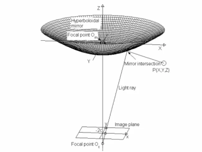
The omnidirectional camera is mounted on top of a mobile robot. An omnidirectional vision consists of a curved mirror and a CCD camera. In this paper, a hyperbolic mirror is used as a curved mirror [2]. The geometry of the hyperbolic omnidirectional camera is shown in Fig. 1. A light ray which goes ahead to mirror focal point Om from the object point P(X,Y,Z) is reflected toward a camera lens focal point O in the c
Fig. 1. Geometry of hyperboloidal project
field of 360o around the Z axis. An omnidirectional image on image plane is generated from this process. The hyperbolic equation of the mirror is represented,
) 1 (
2 2 2
2 2
− + = + −
b c Z a
Y X
(1)
where a2+b2 , a and b are parameters of the hyperboloidal mirror shape.
The relationship between a real world 3D position Z T
Y X, , )
=(
P and an image position p(x,y) is presented as follows:
⎥⎦
⎢ ⎤
⎣
⎡ + +
−
−
= −
⎥⎦
⎢ ⎤
⎣
⎡
Y X Z Y X bc Z c b
c b f y
x
2 2 2 2
2
2 2
2 ) (
)
( (2)
where f is the focal length of a camera.
3. Optical flow pattern analysis
3.1 Optical flow in omnidirectional image
The hyper-catadioptric projection equation from Eq. (2) can be written as follows [4] [12]:
FP x=
λ (3)
where x=(x,y,0)T,F=diag(1,1,0)∈ℜ3×3, P=(X,Y,Z)T and
) (
2 ) (
2 2
2 2 2 2
2
c b f
Z Y X bc Z c b
−
+ +
−
= −
λ (4)
The rigid motion of a scene point P which is related to a moving camera can be described as a linear velocity V =(Vx,Vy,Vz)T and an angular velocity
T z y
x, , )
(Ω Ω Ω
Ω= . The instantaneous velocity of a scene point P in camera frame is evolved as [3]:
P Ω V
P&=− − × (5)
After all, optical flow x& =(x&,y&)Tis obtained as follows:
Ω
⎥⎥
⎥⎥
⎦
⎤
⎢⎢
⎢⎢
⎣
⎡
−
− +
−
− +
⎥⎥
⎥⎥
⎦
⎤
⎢⎢
⎢⎢
⎣
⎡
+ +
−
+ +
−
⎥=
⎦
⎢ ⎤
⎣
⎡
x xy y
Zx
y x Zx xy
V yZ y x xy
xZ x xy x
y x
β α β
α λ
β α λ β
α
β ε ελ α ελ
β ε ελ α ελ λ
2
2 2 2
1 1
1
&
&
(6)
whereα=b2+c2,β= f(b2−c2)and ε = −2bc/(βP).
3.2 FOE and FOC vectors
In this paper, a mobile robot moves only in X −Y
plane. Therefore, the linear velocity is T
y
x V
V , ,0)
=( V
and the angular velocity is Ω =(0,0,Ωz)T. The hyper- catadioptric optical flow Eq. (6) is rewritten as [12]:
z y
x
x y V V x xy
xy x y
x ⎥Ω
⎦
⎢ ⎤
⎣
⎡ + −
⎥⎦
⎢ ⎤
⎣
⎡
⎥⎥
⎦
⎤
⎢⎢
⎣
⎡
+
− +
= −
⎥⎦
⎢ ⎤
⎣
⎡
2 2
1 1 1
ελ ελ
ελ ελ
& λ
&
(7)
If the motion of a mobile robot is not only rotation, there are two points (x,y)T where optical flow (x,y)Tof Eq. (7) is zero. In particular, in case of translation motion, two points
y T
x, )
( are obtained as follows:
⎥⎥
⎦
⎤
⎢⎢
⎣
⎡
± +
⎥=
⎦
⎢ ⎤
⎣
⎡
x y x
x y
x VV V
V V y V
x
) / (
1
2
ελ 2
if Vx ≠0 (8)
⎥⎥
⎦
⎤
⎢⎢
⎣
⎡
± +
⎥=
⎦
⎢ ⎤
⎣
⎡
y y y x
y
x V
V V V V y V
x /
) (
1
2
ελ 2
if Vy ≠0 (9)
These two points (x,y)Tare candidates for Focus-of- Expansion (FOE) and Focus-of-Contraction (FOC) points. In
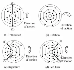
Fig. 2. Optical flow, FOE (1) and FOC (2) vectors
Fig. 3. Estimated optical flow, FOE(1) and FOC(2) vectors in omnidirectional image
Fig. 4. Moving object detection algorithm
omnidirectional image, the image point where the optical flow vectors seem to be emerging is a FOE point, on the contrary, the image point where optical flow vectors seem to be vanishing is a FOC point. In this paper, FOE and FOC vectors are defined as vectors from center point to FOE and FOC points in omnidirectional image, ,respectively.
Defined FOE and FOC vectors are described in Fig. 2. FOE and FOC vectors display (1) and (2) arrows. However, they do not exist in rotation. If a mobile robot with an omnidirectional camera has a straight forward motion, estimated FOE and FOC vectors are situated at opposite direction as shown in Fig. 2 (a).
The shape of optical flow is symmetric in according to the line of FOE and FOC vectors. FOE and FOC vectors are described on left and right sides of omnidirectional image on the motion of right and left turns, respectively. In case of right turn and left turn, they are characterized as shown in Fig. 2 (c) and (d).
In the characteristic of optical flow pattern, the length optical flow becomes large in the middle part of between FOE and FOC vector. On the contrary, it becomes small in the neighborhood of between FOE and FOC vector. These patterns are used for determining the relative evaluation of optical flows. FOE (1) and FOC (2) vectors estimated experimentally in omnidirectional image are shown in Fig. 3.
When a mobile robot with an omnidirectional camera has four motions including straight forward, rotation, right turn and left turn, results of the estimated optical flow and FOE and FOC vectors are similar to characteristics of those shown in Fig. 2.
4. Moving Object Recognition
The process flowchart for detecting moving objects is shown in Fig. 4. It can be achieved by the following procedure.
Step 1: The captured original image is monochromized to 8 bit gray image.
Step 2: The optical flow is calculated in omnidirectional image. The optical flow is computed using the known spatial local optimization proposed by Lucas and Kanade method [13] for fast processing time. The spatial local region is [10×10] pixels.
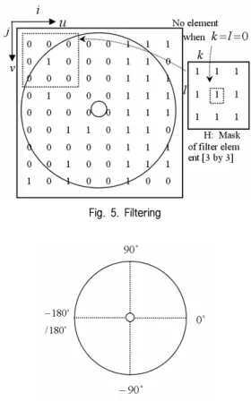
Step 3: The noise of the calculated optical flow is eliminated using an filtering. The noise of optical flow is caused by the vibration of a mobile robot. Before the filtering is accomplished, optical flows which are estimated at local region of [10×10] pixels are classified into two groups in according to the direction of optical flow vector. The direction of optical flow vector is classified by the size of internal angle between an optical flow vector and the u-axis of Cartesian coordinates; u and v axis in omnidirectional image. If the absolute value of internal angle is larger than 90o , zero is assigned to the direction of optical flow vector. Otherwise, if
Fig. 5. Filtering
Fig. 6. position-angle of optical flow
the absolute value of internal angle is smaller than 90o, one is assigned to the direction of optical flow vector. The element (zero and one) image of the classified optical flow is shown in Fig. 5.
Suppose that the element image of the classified optical flow and the mask of filter element are A( ji, )and H( ji, ) respectively, the following convolution is calculated,
∑
∑
=− =−+ +
= 1
1 1
1
) , ( ) , ( )
, (
l k
l K H l j k i A j
i
f (10)
where K= l≠0 and ( ji, ) is the coordinates of optical flow. The filtering of an image is accomplished as follows:
⎪⎩
⎪⎨
⎧
≤
=
<
<
=
≥
=
. 2 ) , ( ,
0 ) , (
, 6 ) , ( 2 ), , ( ) , (
, 6 ) , ( ,
1 ) , (
j i f if j
i A
j i f if j i A j i A
j i f if j
i A
(11)
The maximum and minimum of f( ji, ) are 8 and 0.
Filter thresholds 6 and 2 are determined on the basis of the truth 66.7 % of same elements 1 or 0 around ( ji, ). In the middle part {3,4,5} of filter output, the filter output keeps up
the current element A( ji, ).
Step 4: FOE and FOC vectors are estimated from the filtered optical flow.
FOE and FOC points can be ideally obtained from positions where the size of the optical flows is zero. However, it is difficult to find FOE and FOC points directly as shown in Eq.
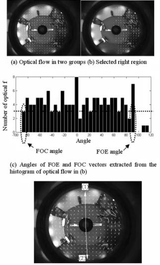
(7). In this paper, FOE and FOC vectors are found using the histogram of angles of optical flow. To begin with, the angle of optical flow is defined as the angle of start point of optical flow in omnidirectional image. The histogram is investigated in the selected right region from two groups classified in Step 3.
Figure 6 shows the angles of optical flow defined in omnidirectional image. The maximum hmax and minimum hmin of histogram angles become the candidates of angles of FOE and FOC vectors. The threshold is used to find proper maximum and minimum of histogram angles. When the mobile robot moves forward, the angles of FOE and FOC vectors are determined as follows:
⎪⎪
⎪⎪
⎩
⎪⎪
⎪⎪
⎨
⎧
=
=
=
=
−
≥ +
max min min
max min
max
vector FOC of angle
vector FOE of angle otherwise
vector FOC of angle
vector FOE of angle
180
h h h
h h
h
(12)
Fig. 7 shows the extraction process of FOE and FOC vectors. One region of two groups classified in Step 3 is elected as shown in Fig. 7 (b). In Fig. 7 (c), the histogram of the position-angle of optical flow is investigated in the selected right region. The position-angle of optical flow is defined as a polar angle of a position where an optical flow is computed as shown in Fig. 6. The interval of angle axis in histogram is calculated by dividing the range of the angle of optical flow by 36.
The maximum and minimum intervals approach to 10 and 0 degrees. In Fig. 7 (c), the angle interval is 5.74 degrees.
Though the optical flow is filtered in Step 3, it is possible to be misclassified. Since the position of optical flow is not radiately scattered around the center point of omnidirectional image as shown in Fig. 7 (a) and (b), the threshold parameter of histogram is used.
When the number of histogram is larger than the threshold parameter, the maximum and minimum of histogram angles are selected as candidates of angles of FOE and FOC vectors.
The threshold parameter is experientially given as 3 in this paper. When the mobile robot moves to straight forward as shown in Fig. 7 (b), the maximum and minimum of the selected histogram are angles of FOE and FOC vectors,
respectively. Angles of FOE and FOC vectors measured in Fig. 7 (c) are 90.74 and -87.13 degrees.
Step 5: The moving object is extracted through the relative evaluation of optical flows which is derived from the pattern of optical flow.
If the motion of a mobile robot is not rotation, FOE and FOC vectors are used as reference vectors. The length of optical flow becomes small in the neighborhood of FOE and FOC vectors, but large in the middle of between FOE and FOC vectors. If the motion of a mobile robot is only rotation, FOE and FOC vectors do not exist. In this case, the length and direction of optical flow are investigated. This characteristic supplies clue for extracting moving objects from optical flow.
Two evaluation parameters are suggested to discriminate optical flows of moving objects from whole optical flows.
Suppose that the optical flow
vrijon omnidirectiional image is calculated in Step 2, and v'rijis the projected vector of
vrij
into the virtual cylindrical image plane. Let optical flow vector
Fig. 7. Extraction of FOE and FOC vectors
Fig. 8. Definition of evaluation parameters
tij
E and E ri
be vrij, for i=1 and 2, which i is the classified groups of optical flows and j=1,...,M or N , M and N are the number of optical flows when i=1 and i=2 , respectively. In cases of translation and left turn and right turn, one evaluation parameter
tij
E is defined as follows:
(
−0.5sin( )+1)
= ij
v v
v v t
ij ij
ij ij
ij L
L L
E L θ
θ θ r r r r
(13)
Where
vij
Lr and
vij
Lθr are the length of vrij and
vrij
θ . and Lvrij =[Lvr11,Lvr12,...,Lvr1M, Lvr21,Lvr22,...,Lvr2N], and
].
,..., , , ,..., , [
2 22 21 1 12
11 M N
ij v v v v v v
v L L L L L L
Lθr = θr θr θr θr θr θr
vij
Lr
and
vij
Lθr are the norm of
vij
Lr and
vij
Lθr .
ij
ij v
v L
Lr / r and
ij
ij v
v L
Lθr / θr mean the normalized quantities of
vij
Lr and
vij
Lθr.
i ij
ij α β
θ =180 / . Valuesvrij,
vrij
θ , αij and βi are shown in Fig. 8. As shown in Fig. 8, βi+β2 =360, 0≤αij ≤βi. In case of rotation, let optical flow vector be
vrij, for L
i=1,..., which Lis the number of optical flows The evaluation value
ri
E is defined as follows: where
vi
Lr is the length of vri,
Fig. 9. Sample frames of detected moving objects in four motions
⎟⎟
⎠
⎞
⎜⎜
⎝
= ⎛
sin 2i
i i i
d
v v
r L
E L θ
r r
(14)
] ,..., ,
[ 1 2 L
i v v v
v L L L
Lr = r r r , and
vi
Lr is the norm of
vi
Lr .
i i
i r f
d θ θ
θ = + and r i
i θ
θ = 90+ in clockwise rotation,
i
ri θ
θ = 90− in counterclockwise rotation, θi is the position- angle of optical flows and
fi
θ is the polar angle of the position vector of optical flows.
Finally, if the calculated
tij
E or
ri
E of each optical flow is larger than a given value, the calculated optical flow vector is turn out as the vector of moving object. The spatial local region of an detected optical flow vector becomes the region of moving objects.
5. Experiment and Discussion
In experiment, the omnidirectional camera is mounted on top of a mobile wheelchair robot moving in indoor environment. Because the motion pattern of a mobile robot is various in real indoor environment, it is very difficult to evaluate the proposed moving object detection method reasonably and quantitatively. In this paper, experimental results of basic motions such as straight forward, left turn, right turn and rotation were investigated in order to confirm the proposed method.
In each consecutive motion except rotation, FOE and FOC vectors were estimated and moving objects were
(a) Straight forward Table 1. Error rate in four motions
Motion Mean of error
rate [%] # frame
Movie 1 Straight 3.25 54
Movie 2 Left turn 3.02 79
Movie 3 Right turn 4.80 75
Movie 4 Rotation 4.27 81
detected. In experiment condition, the walking man is assigned for moving object. The captured omnidirectional image size is 320×240 pixels, the frame rate of input image is 15 fps (frames per second) and color is 24 bit RGB color. An optical flow was computed using known a spatial local optimization for fast processing time.
Fig. 9 shows sample frames of detected moving objects in four motions. In order to evaluate the proposed method, the error percentage is defined as the percentage ratio of false optical flows to detected moving objects per each frame.
The mean of the error percentage is listed in Table 1. The number of frame in straight forward, left turn, right turn, rotation is 54, 79, 75 and 81 frames, respectively. Means of error ratio in four motions are smaller than 5 % as shown in Table 1.
Fig. 10 describes the false detected optical flow region of moving objects among whole detected optical flow regions according to a series of frame in four motions.
Because the distance between a robot and moving objects is not enough far in indoor environment and the motion of moving object is freestyle, the size of a spatial local region used for calculating the optical flow has influence on the number of detected optical flow vectors. Therefore, we investigated not the ground truth which is defined as optical flow vectors corresponding to the moving object but the error percentage.
The major reason of moving objects detection failure was the sensitivity of optical flow caused by the vibration of a mobile robot and the brightness change in experiment environment. The shadow of object also occurred the detection failure. The wrong estimated optical flow disturbs right FOE and FOC vectors extraction as well as the true moving object detection. As future work, the work is needed to reduce the vibration of mobile robot. Particular, if we use Eqs. (8) and (9), FOE and FOC vectors can be extracted from only linear velocities Vx and Vy of the mobile robot regardless of the optical flow.
6. Conclusion
In this paper, a moving object detection method was proposed in mobile robot with an omnidirectional camera. The specific optical flow pattern was theoretically and
Fig. 10. Optical flow number of detected moving objects in four motion
experimentally investigated in omnidirectional image. The optical flow of the moving object was detected through the relative evaluation of optical flow which had been derived from the optical flow pattern.
(b) Left turn
(c) Right turn
(d) Rotation
[1] R.L. Madarasz, L.C. Heiny, R.F. Cromp and N.M.
Mazur, “The design of an autonomous vehicle for the disabled,” IEEE Journal of Robotics and Automation, Vol.2, No.3, pp. 117-126, 1986.
[2] T. Svoboda, T. Pajdla and V. Hlavac, “Central Panoramic Cameras:Geometry and Design,” Research Report K335/97/147, Czech Technical University, 1997.
[3] J. Gluckman and S.K. Nayer, “Ego-motion and omnidirectional camera,” Proc. of Int. Conf. Computer Vision, pp. 999-1005, 1998.
[4] O. Shakernia, R. Vidal and Sastry, Infinitesimal motion estimation from multiple central panoramic views,” Proc.
IEEE Workshop on Motion and Video Computing, pp.
229-234, 2002.
[5] E. Menegatti, A. Pretto and E. Pagello, “A new omnidirectional vision sensor for Monte-Carlo localization,” Proc. of the 2004 Int. RoboCup Symposium, LNAI, Vol.3276, pp.97-109, 2005.
[6] H. Koyasu, J. Miura and Y. Shirai, “Mobile robot navigation in dynamic environments using omnidirectional stereo,” Proc. IEEE International Conference on Robotics and Automation, Vol.1, pp.
893-898, 2003.
[7] Y. Yagi, K. Imai, K. Tsuji and M. Yachida, “Iconic memory-based omnidirectional route panorama navigation,” IEEE Trans. Pattern Analysis and Machine Intelligence, Vol.27, No.1, pp. 78-87, 2005.
[8] T. Gandhi and M. Trivedi, “Motion analysis for event detection and tracking with a mobile omnidirectional camera,” Multimedia Systems, Vol.10, No.2, pp. 131- 143, 2004.
[9] M. Watanabae, N. Takeda, K. Onoguchi, “Moving Obstacle Detection and Recognition by Optical Flow Pattern Analysis for Mobile Robots,” Advanced Robotics, Vol.12, pp.791-816, 1999.
[10] A. Talukder, S. Goldberg, L. Matthies, and A. Ansar,
“Real-time detection of moving objects in a dynamic sensor from moving robotic vehicles,” Proc. of Int. Conf.
Intelligent Robotics and systems, pp. 1308-1313, 2003.
[11] I. Stratmann and E. Solda, “Omnidirectional vision and inertial clues for robot navigation,” Journal of Robotic Systems, Vol.21, No.1, pp. 33-39, 2004.
[12] J.C. Kim, Y. Suga, “An Omnidirectiaional Vision-based Detection in Mobile Robot,” International Journal of Control , Automation, and Systems, Vol.5, No.6, pp.
663-673, 2007.
[13] B.D. Lucas and T. Kanade, “An iterative image registration technique with an application to stereo vision,” Proc. 7th Int. Joint Conf. on Artificial Intelligence, pp. 674-679, 1981.
Yasuo Suga 1970 Keio Univ. Mechanical
Engineering (B.E) 1972 Keio Univ. Mechanical
Engineering (ME) 1977 Keio Univ. Mechanical
Engineering (Ph.D) 1980~Present Professor, Keio Univ.
관심분야 : Intelligent robot, Robot vision, Intelligent control 김 영 명
1987 성균관대학교 산업공학 과(학사)
1989 한국과학기술원 산업공 학과(석사)
2001 한국과학기술원 경영공 학(박사)
2005~2007 KT 기술전략 및 로봇사업 담당 상무 2007~현재 KT IT기획실 IT 혁신담당 상무 관심분야 : 네트워크로봇, 감성형 로봇서비스, 통신망
운용관리, 기술경영, IT 거버넌스 김 종 철 2000 창원대학교 제어계측공
학과(학사)
2002 포항공과대학교 전자전 기공학전공(석사) 2007 Keio Univ. Integrated
Design Engineering (Ph.D)
2007~현재 KT 미래기술연구소 선임연구원
관심분야 : 지능로봇, 지능제어, 로봇비전, 인간로봇상호 작용, 로봇감성기술
참 고 문 헌
![Fig. 9. Sample frames of detected moving objects in four motions ⎟⎟ ⎠⎞⎜⎜⎝=⎛sin2i iii dvvrLELθrr (14) ],...,,[ 1 2 LivvvvLLLLr=rrr , and v iLr is the norm of v iLr](https://thumb-ap.123doks.com/thumbv2/123dokinfo/5337865.393394/6.892.107.411.148.522/sample-frames-detected-moving-objects-motions-dvvrlelθrr-livvvvllllr.webp)

