ICCAS2005 June 2-5, KINTEX, Gyeonggi-Do, Korea
1. INTRODUCTION
The mobile robot mainly calculates its position with data acquired from a rotary encoder, which is connected to wheel, and from a gyroscope sensor, but it won’t receive correct position because of slippage, a rough surface, and sensor error such as gyroscope drift. To overcome these errors, many solutions have been proposed. Some researchers presented a method which estimates the current position by applying information obtained by a rotary encoder and ultrasonic sensor to extended the Kalman filter.[1][2] , A researcher updated the positioning of mobile robots by fusing by means of an extended Kalman filter with data from multisensor such as magnetic compass, gyroscope, rotary encoder and so on.[3] These methods need much calculation for a mobile robot to perform a task, therefore it results in a drop in total system efficiency. Another disadvantage is greater localization uncertainty which develops due to statistical error accumulated from sensors and control over long distances. Another way that was presented in that a robot, equipped with a CCD camera, estimates a position by recognizing a characteristic topography or object, and compares it with the model image saved in advance.[4][5][6] Some researchers presented a method which assumes the position of a robot through geometric calculation, after making a robot recognize a landmark.[5][7] These methods consume unnecessary system for a robot to search.
Fig.1 Between a camera and a point in the real world
2. IMAGE PROCESSING
Input images have the size of 640×480 pixel at every sampling time. It can cause the increase of unnecessary computation to apply preprocessing to total image in order to draw some necessary information. Therefore, the research on
the decrease of computation time by designating a necessary part as a sub-block is being in progress. This section explains edgedetection schemes based on the imageprocessing and the central moment that plays a key role in determining the position of windows. And then it decides the optimal size of windows.
Once the image of an object is received, we must take a course that extracts the features of the object. In this paper, we applied Gaussian mask to remove the image noise for light in indoor environments, and reduced the image scale for origin to make processing time better.
1 2 1 2 4 2 1 2 1 Fig. 2 Gaussian mask
∑∑
+ − = + − = − + + = 1 1 1 1 1 ) 2 , 2 ( ) , ( ) , ( i j l l j y i x I j i G y x I (1)Here, l is the label of image, G( ji, ) is Gaussian mask. In Fig. 2, the moving object is extracted by the difference in image between background image saved in advance and consecutive input images.
Image noise occures during the image process. This noise causes the unnecessary computation of images. The filtering method that was used, was the opening and closing filtering method.
This process gives a number to each object. We can separate an object and search for its feature. Also in this paper, we use for removing labeled objects that is smaller than the established object
A windowed contour is set wrapping the most high, low, left, and right pixel of the object labeled. By these means, we extract the characteristic information of the object.
To get a background image is very important for object segmentation. Therefore, in order to look for a moving object in an environment, which changes continuously, the background image has to be updated. Refer to Fig. 3 and Fig 4.
Mobile Robot Navigation in an Indoor Environment
Sung-Yug Choi*, and Jang-Myung Lee
***Busan Regional Innovation Agency, Busan, Korea (Tel : +82-51-316-9405; E-mail: [email protected])
**Department of Electronic Engineering, Pusan National University, Busan, Korea (Tel : +81-51-510-2378; E-mail: [email protected])
Abstract: To compensate the drawbacks, a new localization method that estimates the global position of the mobile robot by using a camera set on ceiling in the corridor is proposed. This scheme is not a relative localization, which decreases the position error through algorithms with noisy sensor data. The effectiveness of the proposed localization scheme is demonstrated by the experiments.
Keywords: Navigation, mobile robot, image preprocessing
16 1
ICCAS2005 June 2-5, KINTEX, Gyeonggi-Do, Korea
(a) (b) Fig. 3 Robot image in main sever
Fig. 4 Corridor information form mobile robot
3. TRANSFORMATION FROM IMAGE
Image matching method by stereo vision generally is used for acquiring the distance between camera and object We can obtain it between camera and object using a single camera and then, such distance is represented as real coordinates.
C θ
β
( , )x y ( ,P Px y) α 0 1 _ y 2 _ y Object length y yblind length z length x γ SCREEN ) , (xtop ytop ) , (xbottomybottomFig. 5 Transfortation form the image
)
(
tan
1 blind Lengthy
z
−=
α
(2))
(
tan
1 length blind lengthy
y
z
+
=
−θ
(3))
(
tan
1 length blind lengthy
y
x
+
=
−β
(4) θ α γ = − (5) bottomy is a real coordinate corresponding to the lowest pixel of the extracted object in the image. Here, xrobot_positionand
position robot
y _ are each central coordinates of the robot in the x-axis and the y-axis.
)] _ ( ) 90 tan[( _ y screen p z
ybottom = length× °−
α
+γ
× y bottom (6))
2
/
(
_
y
L
y
robot position=
bottom+
(7)(L is the diameter of robot.)
)
_
2
(
tan
_ _ _x
screen
p
y
x
robot position=
robot position×
β
x bottom (8)4. NAVIGATION
In the rear, there is one free-wheeling castor. Although castors have been said to cause slipping during direction changes, it has been proven that this is may not always occur. A more complicated design that allows two DOF-motion in the plane and is based on two wheel-pair assemblies was presented in. However, this robot has been found to be very difficult to control and no satisfactory solution has been found yet.
Y
Xθ
u
1 y 1 x ) , (xy ωL
Rv
Lv
World coordinates Robot coordinatesFig. 6 Navigation of the mobile robot.
In mobile robots it is desirable to place the two drive wheels as far apart as possible, for the following reasons:
1. The stability of the robot is improved.
2. The effect of the encoder resolution on the orientation error of the robot is decreased. In the worst case, the orientation error
∆
θ
is given approximately by follow.a
x
∆
=
∆
θ
(9)
As seen from (9), the orientation error∆
θ
is reduced by increasing the distance between the drive wheels.3. During straight-line motion, mechanical disturbances might cause the motors to run temporarily at different angular speeds, resulting in a temporarily curved path. It can be shown by trigonometry that the radius of the curved path is directly proportional to the wheel separation distance.
4. Differences in the two wheel diameters will also cause a curved path with a radius proportional to the distance a.
ICCAS2005 June 2-5, KINTEX, Gyeonggi-Do, Korea
On the other hand, an exaggerated base width will adversely
affect the mobility within a room. In the present design the distance between the two drive wheels is 300 mm.
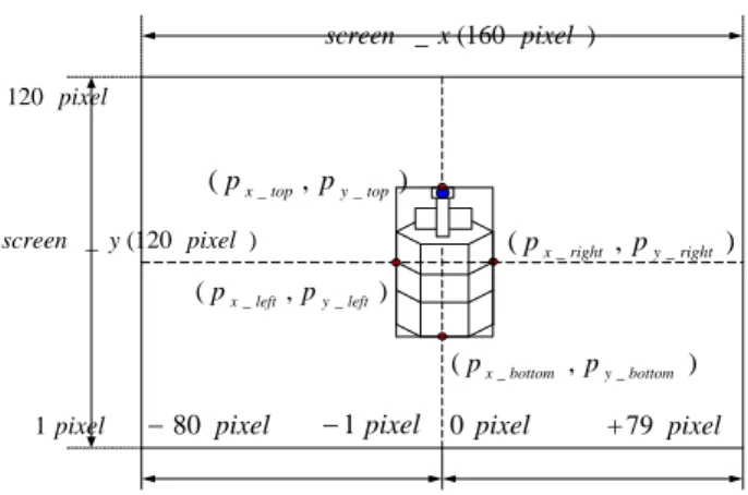
In Fig. 7, we set the screen image as follows. The center is 0 pixel and the furthest left to the furthest right pixel on the screen is from –80 pixel to +79 pixel. screen _x and
y
screen _ are the total number of pixels on each axis.
) 160 ( _x pixel screen ) , (px_top py_top ) , (px_left py_left ) , (px_bottom py_bottom ) , (px_right py_right pixel 0 pixel 80 − +79 pixel pixel 1 pixel 120 pixel 1 − ) 120 ( _y pixel screen
Fig. 7 Main server image
In Fig 7, we obtained real x, y coordinate. If we use these, we can calculate the height, and width of the robot.
Shown in Eq.(10), and (11), we used the proportional relation of geometry. 2 ) 1 2 ( 2 _ L L L z h = length× − (10) 6 ) 5 6 ( 4 ) 3 4 ( 1 _ L L L z L L L z h = length× − = length× − (11)
Using Fig .6,7, and 9, we represented the following formulas. From Eq.(7) )] _ ( ) 90 tan[( _ y screen p z
ytop = length× °−α +γ× y top
(12) O y y_1= bottom− (13) bottom top y y y_2= − (14)
Using Eq.(13), and (14), we can measure the height of the object. length top bottom top length z O y y y z y y y height OBJ × − − = × + = 2 _ 1 _ 2 _ _ (15) Using Eq.(7), yleft and yright are calculated.
) _ 2 ( tan _ x screen p y
xleft = left× β x left (16) ) _ 2 ( tan _ x screen p y
xright= right× β x right (17) From Eq.(18), we can measure the height of the object.
left right x
x width
OBJ_ = − (18)
5. EXPERIMENT AND RESULT
All experiment must be done indoor environment under 700~ 1000lux, because the light is influencing image processing.
Fig 8 Mobile Robot
The state of mobile robot is represented as the vector T
y x, , ]
[ θ
=
Pr , which has the position and the direction like that in Fig. 1. In general, the motion of the mobile robot is modeled in Eq.(19), and (20) which has the translation velocity and the angular velocity.[19]
) ( 2 1 L R v v u= + (19) ) ( 1 L R v v L − = ω (20)
Here, vR , and vL are the right and left velocity.
The L is the distance between two wheels. The velocity P& is represented by Eq.(21) using the Jacobian matrix.
q p J p& = ( )& ⎥ ⎦ ⎤ ⎢ ⎣ ⎡ ⎥ ⎥ ⎥ ⎦ ⎤ ⎢ ⎢ ⎢ ⎣ ⎡ = ⎥ ⎥ ⎥ ⎦ ⎤ ⎢ ⎢ ⎢ ⎣ ⎡ ω θ θ θ u y x 1 0 0 ) sin( 0 ) cos( & & & (21)
The position vector P is the integration form of Eq.(21) like Eq.(22). ⎥ ⎦ ⎤ ⎢ ⎣ ⎡ ⎥ ⎥ ⎥ ⎦ ⎤ ⎢ ⎢ ⎢ ⎣ ⎡ = ⎥ ⎥ ⎥ ⎦ ⎤ ⎢ ⎢ ⎢ ⎣ ⎡ ω θ θ θ u y x 1 0 0 ) sin( 0 ) cos( & & & (22)
From this Kinematics, we calculate the position of the robot by control period.
In this paper, we equipped a wireless LAN card so as to monitor the state of the robot and to control robot. The LAN used is the PC24E-H-FC model from the Lucent Technology. From part2, we accounted for image preprocessing. By using it, we obtained Fig. 9. Most of the images were extracted but several was disturbed by the light.
Fig. 9 Background image
ICCAS2005 June 2-5, KINTEX, Gyeonggi-Do, Korea
(d) (e)
Fig. 10 The result image of the object segmentation
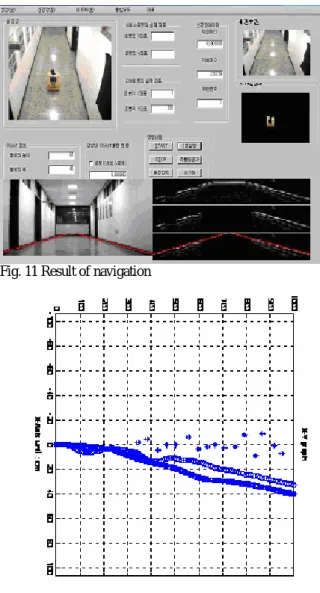
Fig. 11 Result of navigation
Fig. 12. The positions of a robot
Fig. 12 is error of a robot position results from the wheel slippage, a rough surface, and sensor error and so on. And, in Consecutive circles represent the positions that are made by encoder sensor and many star marks represent the positions that are calculated by presented method.
Finalize this paper, a new localization method is proposed, which utilizes the external monitoring camera information under the indoor environment. When the moving object is a mobile robot in the corridor, it helps the localization of robot by estimating the current position through the geometric analysis of the mobile robot image. The exact position of the mobile robot was obtained and proved to be correct by the real
experiments.
Also, it is possible to distinguish between two robots and other objects through the neural network with the data which were acquired by the feature point extraction. This scheme is applied to a number of robots with the new localization method.
REFERENCES
Olson, C.F., “Probabilistic Self-Localization for Mobile Robots” Robotics and Automation, IEEE Transactions Volume: 16 Issue: 1 , Feb. 2000, Page(s): 55 –66
[2] Jetto, L.; Longhi, S.; Venturini, G., “Development and Experimantal Validation of an Adaptive Extended Kalman Filter for the Localizaiton of Mobile Robots”, Robotics and Automation, IEEE Transactions on , Volume: 15 Issue: 2 , April 1999, Page(s): 219 -229
[3] Curran, A.; Kyriakopoulos, K.J., “Sensor-Based Self-Localization for Wheeled Mobile Robots” Robotics and Automation, 1993. Proceedings., 1993 IEEE International Conference on , 1993 , Page(s): 8 -13 vol.1 [4] Ching-Chih Tsai, “A localization system of a mobile robot
by fusing dead-reckoning and ultrasonic easurements”, Instrumentation and Measurement, IEEE Transactions on , Volume: 47 Issue: 5 , Oct. 1998 Page(s): 1399 –1404 [5] Hognbo Wang, Cheolung KANG, Shin-ichirou TANAKA,
Takakazu ISHIMATSU, “Computer Control of Wheel Chair by Using Landmarks”, ’95, KACC(1995. 10.23~25) [6] Mata, M.; Armingol, J.M.; de la Escalera, A.; Salichs,
M.A., “A visual landmark recognition system for topological navigation of mobile robots”, Robotics and Automation, 2001. Proceedings 2001 ICRA. IEEE International Conference on , Volume: 2 , 2001 Page(s): 1124 -1129 vol.2
[7] Atiya, S.; Hager, G.D., “Real-time vision-based robot localization”, Robotics and Automation, IEEE Transactions on , Volume: 9 Issue: 6 , Dec. 1993 Page(s): 785 –800
[8] T. W. Kim, K.H. Lee, “A Study on Approach of Localization Problem Using Landmarks”, KACC, Octobe 1997, Proceedings of the 12th
[9] S. Y. Choi and J. M. Lee, “Lane Recognition and Obstacle Detection Using Moving Windows,” Journal of The
Institute of Electronics Engineers of Korea, vol. 36-S, no.
1, pp. 93-103, Jan. 1999 (in Korean).
[10] S. Y. Choi, T. S. Jin and J. M. Lee, “Optimal Moving Windows for Real-Time Road Image Processing,” Journal
of Robotic Systems, vol. 20, issue 2, pp. 65-77, Feb.
2003on , Volume: 3 , 2001 Page(s): 1619 -1623 vol.3 [11] Rafael G. Gonzalez, Richard E. Woods, “Digital Image
Processing”, Addison-Wesley Publishing company 1993 [12] I. Pitas, “Digital Image Processing Algorithms and
Applications”, JOHN WILEY & SONS, 1999.
[13] Milan Sonka, Vaclav Hlavac and Roger Boyle, ”Image Processing”, Analysis and Machine Vision CHAPMAN & HALL COMPUTING 1993.