• 검색 결과가 없습니다.

Comparison of the Power Consumption between the Ceramic and Wire Bonding Packaging Methods for Solid State Electrochemical Carbon dioxide Sensors

N/A
N/A
Protected

Academic year: 2021

Share "Comparison of the Power Consumption between the Ceramic and Wire Bonding Packaging Methods for Solid State Electrochemical Carbon dioxide Sensors"

Copied!
5
0
0

로드 중.... (전체 텍스트 보기)

전체 글

(1)

Abstract

Tape casting ceramics technology has been adopted for the fabrication of solid state electrochemical CO

2

sensors and the packaging substrates. The fabricated CO
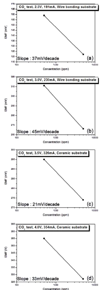
2

sensors exhibit a fast response and a good recovery with the almost theoretical sensitivity of 37 mV/

decade, corresponding to a sensor operating temperature of 373 K. The two packaging methods, the wire bonding package and the sur- face-mounted on the ceramic package, were compared with respect to their power consumption and mass production feasibility. In terms of the ease of fabrication, the surface mount packaging technology is superior to the wire bonding technology but its power consumption is approximately twice that of the wired package.

Keywords: CO

2

sensor, Packaging, Gas sensor, Sensitivity, Power consumption

1. INTRODUCTION

Solid state electrochemical carbon dioxide gas sensors have been used widely in gas sensing applications because of their productivity, durability, and low costs [1,2]. However, the sensors need a high temperature of 400

o

C – 500

o

C for operation. For providing such high temperatures, the sensor is attached to an electric heater. For applications, the combined sensor should be attached to an additional substrate to ensure thermal isolation and prevent heat conduction through the connecting paths to the electronic circuits that are mainly formed on PCB.

The wire bonding package using a metal can is the most popular method for commercial sensors. In this structure, air with a thermal conductivity of 0.024 W/m·K (compared to 35 W/m·K for Al

2

O

3

) is used as a thermal insulator for maximizing the localization of heat [3]. The ceramic substrate is composed of LTCC material that is a thermal insulator with a thermal conductivity of 3.3 W/m·K and is mostly used for high temperature applications because of its stability [4].

The problems reported for these two types of substrates include

the power consumption and the mechanical strength. The wire bonding type is thermally well isolated by air and consuming a low power. However, owing to the limits of the material properties of the Pt or Au wires, frequent failures occur as a result of mechanical shock or creep [5]. In comparison, the ceramic substrate has a high strength and tolerance to hostile conditions but its relatively high thermal conductivity causes a high power consumption.

Therefore, the differences in the stability and power consumption between the two substrates should be analyzed for optimizing these trade-offs. In this study, the power consumption properties are mainly measured by attaching a solid state electrochemical carbon dioxide sensor to both the substrates. The temperature of the sensor is calculated from the slope of the Nernst plot. For example, at the same value of the slope of the sensor, the power consumption can be compared at the same temperature.

2. EXPERIMENTAL

2.1 Preparation of the CO

2

sensor substrate

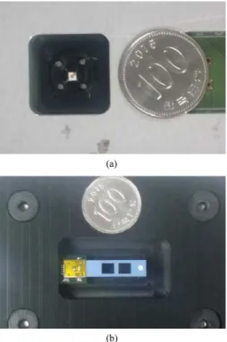
The sensor used in this experiment is a solid state electrochemical carbon dioxide sensor fabricated using the tape casting method from Amotech, Corp. The size of the sensor is 2 x 2 mm with a thickness of 0.8 mm after sintering. It is mounted on wire bonding and ceramic substrates, respectively.

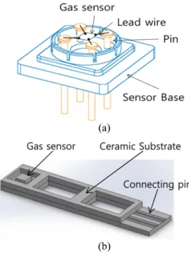
The structures of the two substrates are shown in Fig. 1. The Materials science and Engineering, Korea Advanced Institute of Science and

Technology (KAIST), 291 Daehak-ro, Yuseong-gu, Daejeon 305-338, Korea

+

Corresponding author: [email protected]

(Received: May 20, 2016, Revised: May 27, 2016, Accepted: May 30, 2016)

This is an Open Access article distributed under the terms of the Creative Commons Attribution Non-Commercial License(http://creativecommons.org/

licenses/bync/3.0) which permits unrestricted non-commercial use, distribution,

and reproduction in any medium, provided the original work is properly cited.

(2)

wire bonding substrate has a molded packaging using a polypropylene body and has four titanium (Ti) pins for wire bonding. The pitch between the Ti pins are 6 mm each and size of the substrate is 20 x 20 mm; the height of the Ti pins is 9 mm.

The Pt wires are connected to the sensor and are welded to these pins. Thus, a four electrode hanging structure is formed. This structure uses air that has a thermal conductivity of 0.024 W/m·K, as the thermal insulator. Compared to Al

2

O

3

, it is 1000 times lesser; hence, the power consumption would be significantly less.

Ceramic substrates are composed of LTCC material and are fabricated by a tape casting method from Amotech Corp.

LTCC has a thermal conductivity of 3.3 W/m·K that is ten times lower than that of Al

2

O

3

. Thus, it has an advantage on Al

2

O

3

in terms of the thermal isolation. Its length and width are

30 mm x 7 mm, respectively, and its height is 1.7 mm, for attaching the carbon dioxide sensor. To minimize the power dissipation through the substrate body, the contact area of the sensor on the substrate is designed like a + shaped hole at the head of the substrate, as shown in Fig 2. Thus, the corner of the sensor where the Pt contacts exist is placed only on the silver pad on the substrate using silver paste. The square holes on the body can also reduce heat dissipation for power saving and prevent heat transfer to the tail of the substrate for protecting the connected PCB board that cannot tolerate the high thermal energy from the heater [4].

2.2 Measurement of the CO

2

sensor

Pictures of the sensor products are shown in Fig. 3. The sensors are placed in an appropriate gas testing chamber for the gas test, as shown in Fig. 4. The chamber is connected to the gas testing system constructed for the CO

2

gas test. Schematics of the gas testing system are shown in Fig. 5. It is composed of a gas supplying system, a testing chamber, and power supply units. The testing chamber consists of multiple plates and a PCB board. The multiple plates enable the gas injected into the chamber to be distributed to each sensor. The PCB board supplies voltage to each sensor and delivers the output signals to a data logger. The testing chamber can accommodate 4–16 sensors, separately, for testing various operating conditions.

In this experiment, only one sensor is tested in the chamber for reading the voltage and current displayed on the power supply unit. By passing 500 sccm of 500 ppm and 5000 ppm CO

2

gases, respectively, the EMF values of the sensor at each concentration can be measured precisely by changing its heating power.

The relationship between then EMF value and concentration of the gas contents can be expressed as,

(1) E E

0

2.303RT

--- 2F P

CO

[

2

] log –

= Fig. 1. Substrate design for the experiment: (a) wire bonding type

substrate with the sensor (b) ceramic substrate with a square hole in the body with the sensor

Fig. 2. Structure of the ceramic substrate (a) top and (b) side view

Fig. 3. Pictures of the sensor products: (a) wire bonding substrate (b)

ceramic substrate

(3)

(2) can be expressed as V/decade. It is called the Nernst slope and contains information regarding the temperature. Therefore, from the slope of the differences in the EMF obtained by changing the concentration, the temperature of the sensors can be calculated.

Thus, the power consumption studied previously can be compared based on the temperature of the sensors. As a result, the efficiency of the heating power consumed for increasing the temperature of each substrate can be compared quantitatively.

3. RESULTS AND DISCUSSIONS

3.1 Results

The response behaviors of both the sensors at a typical power are shown in Fig. 6. As the temperature increases, the variation in the EMF value becomes significant. Therefore, the slope will increase. If a plot of the concentration vs the EMF called the Nernst plot is drawn, as shown in Fig. 7, the slope of the plot would contain information regarding the temperature.

Using the slope value, the actual temperature of the sensor can be calculated from Eq. (2). The power consumption according to the slope and temperature is summarized in Table 1.

3.1.1 Comparison of the power consumption and temperature between the two types of substrates

The power consumption for all the sensor conditions along with the calculated temperature is shown in Table 1. According to the data, the wire bonding substrate consumes lesser power than the ceramic substrate, even at higher temperatures. This was predicted previously because the thermal conductivity of air is 100 times Fig. 4. Pictures of the sensor products placed in the testing chamber:

(a) wire bonding type (b) ceramic type.

Fig. 5. Schematics of the gas testing system: (a) gas supplying sys- tem, multiple plate structure and PCB board within the gas chamber: (b) the wire bonding type and (c) ceramic type

Table 1. Power consumption according to the slope and temperature in the wire bonding type and the ceramic type Substrate type Power consumption Slope Temperature Wire bonding 477.5 mW 37 mV/decace 373 K

Wire bonding 690 mW 45 mV/decade 454 K

Ceramic 1141 mW 21 mV/decade 212 K

Ceramic 1416 mW 33 mV/decade 333 K

(4)

Fig. 6. Response behavior of the wire bonding substrate at (a) 477.5 mW and (b) 690 mW, and the ceramic substrate at (c) 1141 mW and (d) 1416 mW.

Fig. 7. Nernst plot of the wire bonding substrate at (a) 477.5 mW and

(b) 690 mW, and the ceramic substrate at (c) 1141 mW and

(d) 1416 mW.

(5)

two other effects reasons remain fixed for similar conditions.

Thus, for decreasing the power consumption, the wire bonding type is recommended and a decrease in the wire bonding point would be beneficial.

4. CONCLUSIONS

A solid state electrochemical carbon dioxide sensor needs a high temperature owing to its operating principle, for ion diffusion through the solid electrolytes. For enabling such conditions, an electrical heater is mostly used for increasing the sensor temperature. A sensor with a considerable tolerance and an efficient substrate is required when electrical heating is used. In this study, two types of substrates, the wire bonding type and the ceramic type, are studied. They have differences in their thermal insulating properties; hence, their power consumption is different.

For decreasing the consumed power, the wire bonding type is recommended compared to the ceramic type. However, the ceramic type is easier to fabricate and convenient for contact with the PCB for supplying power and reading the signals. The ceramic type also exhibits a more stable behavior at high temperatures than the wire bonding type because of the limitations in the material

ACKNOWLEDGMENT

This study was supported by Amotech Corporation for the carbon dioxide sensor project in 2015.

REFERENCES

[1] C. O. Park, S. A. Akbar, and W. Weppner, “Ceramic elec- trolytes and electrochemical sensors”, Journal of Mate-rials Science, Vol. 38, pp. 4639-4660, 2003

[2] C. O. Park and S. A. Akbar, “Chemical sensors for pollution monitoring and control”, Journal of Materials Science, Vol.

38, pp. 4237, 2003

[3] G.S. Chung and J.M. Jeong, “Fabrication of micro heaters on polycrystalline 3C-SiC suspended membranes for gas sensors and their characteristics”, Microelectronic Engi- neering, Vol. 87, pp. 2348-2352, 2010

[4] H. J. Han, T. W. Kim, K. M. Park, and C. O. Park, “Carbon dioxide sensor substrate for surface mounted packaging”, Journal of sensor science and technology, Vol. 24, No. 3, pp. 159-164, 2015

[5] C.O Park, S.A Akbar, and J Hwang, “Selective gas detec-

tion with catalytic filter”, Materials Chemistry and Physics,

Vol. 75, pp. 56-60, 2002

수치

Fig. 2. Structure of the ceramic substrate (a) top and (b) side view
Fig. 5. Schematics of the gas testing system: (a) gas supplying sys- sys-tem, multiple plate structure and PCB board within the gas chamber: (b) the wire bonding type and (c) ceramic type
Fig. 7. Nernst plot of the wire bonding substrate at (a) 477.5 mW and (b) 690 mW, and the ceramic substrate at (c) 1141 mW and (d) 1416 mW.

참조

관련 문서

웹 표준을 지원하는 플랫폼에서 큰 수정없이 실행 가능함 패키징을 통해 다양한 기기를 위한 앱을 작성할 수 있음 네이티브 앱과

The index is calculated with the latest 5-year auction data of 400 selected Classic, Modern, and Contemporary Chinese painting artists from major auction houses..

It considers the energy use of the different components that are involved in the distribution and viewing of video content: data centres and content delivery networks

The “Asset Allocation” portfolio assumes the following weights: 25% in the S&P 500, 10% in the Russell 2000, 15% in the MSCI EAFE, 5% in the MSCI EME, 25% in the

1 John Owen, Justification by Faith Alone, in The Works of John Owen, ed. John Bolt, trans. Scott Clark, "Do This and Live: Christ's Active Obedience as the

In an all-solid-state lithium-sulfur battery manufactured using a composite solid electrolyte, the ratio of carbon, a conductive material added to improve the

In this study, the finite element analysis was used to predict and obtain the material properties of the carbon fibers and the resin even if the carbon fiber laminate and the

The limit is therefore the carbon char as a carrier utilizing only 27% of available hydrogen but sequestering 91kg of carbon dioxide (as measured experimentally) per million