다목적선박의공기조화장치의설계
정 영 록 / (주)신성마린엔지니어링, [email protected]
è æ è / 국방기술품질원 부산국방벤처센터, [email protected]
선박용 공기조화 장치의 설계에 대하여 수순에 의한 방법과 설계사례를 소개 하고자 한다.
서 언
선박은 사용 목적과 그 용도에 따라 여러 종류로 분류 되는데, 이러한 분류의 선박은 선형(船型)과 사용목적에 적합한 냉동 및 공기조화 장치가 설계 되어져야 한다.
따라서 선박 냉동 및 공기조화장치를 잘 설계하기 위해서는 선박의 종류와 사용목적과 구조의 특성을 잘 이해하고 대상선박의 조선 기술적인 사항과 그 에 관련된 Rule과 Regulation 등을 잘 숙지하여야만 설계목적에 부합하는 가장 이상적인 냉동 및 공기 조화장치를 설계 할 수 있을 것이다.
본고에서는 2007년 Singapore에서 건조한 다목적
작업선인“Multi purpose field support vessel”에 적용한 HAVC system의 설계를 위한 조건과 설계 방법을 소개하고자 한다.
공기 조화장치의 설계 선박의 제원
Length over all = 74.87 m Length b.p.p = 67.20 m Bredth = 16.40 m Depth maindeck = 7.45 m Accommodation = 31 persons 설계조건(1) Design condition (표 1)
The main system design is based on 50% fresh
[그림 1] Singapore에서 건조한 다목적 작업선(Multi purpose field support vessel)
air supply, 50% return air. Please see Air Balance Scheme, and 100% fresh air for intermediate season.
Fresh air rate for each person = 30㎥/h fresh air per person.
(2) Power supply : 3 × 440 V, 60 Hz
(3) Control power : 1 × 220 V, 60 Hz (4) Refrigerant : Direct expansion of R 404 A (5) Cooling water : Freshwater 36℃
(6) Heating Medium : Electric heating
(7) Humidification : Drink water spray humidi- fying with compressed air
(8) Classification : DNV (9) Flag : Norway(NMA) (10) Regulations : ISO 7547
SOLAS 1947 with the latest amendments of 2000 & 2002
(11) Motors : Our quotation includes marine motors.
Enclosure IP 55, insulation class F., motor space heater to be supplied.
열부하 계산(Heat Lead Calculation) (1) Design condition
1) Temperature & Humidity condition(표 2)
<표 1> 외기 및 실내온도 조건 <표 2> 설계조건
NO Location Temp(℃)
1 Ambient air 45
2 Deck exposed in sunshine 65
3 Deck exposed in sunshade 55
4 Wall exposed in sunshine 55
5 Wall exposed in sunshade 47
6 Air conditioning space 24
7 Passageway & corridor 27 8 Non air-conditioning space 40
9 Unitary toilet 27
10 Public toilet 27
11 Galley 37
12 Engine Room 50
Cooling Heating
Outside: 40℃ DB, 70% RH -20℃ DB
Inside: 28℃ DB, 50% RH 20℃ DB, approx : 50% RH
Max. Ambient. air 45℃ D.B 95% RH Design out side air 35℃ D.B 75% RH
Inside air 24℃ D.B 50% RH
<표 3> 외기 및 주변온도 조건 <표 4> 열전달율
NO Location kcal/㎡.h℃
1 Ceiling
Non air-cond 4.0
Corridor 2.55
Lav. Bath 2.0
Exposed 0.9
2 Floor
Non. Air-cond 4.0
Corridor 2.55
Eng. Space 1.5
Galley 1.15
3 Bulkhead wall
Shell side(50t insulation) 1.5 ~ 0.9 Shell side(25t insulation) 1.15 ~ 0.9
Divided 1.44 ~ 2.24
<표 5> 환기 횟수
N
O Space Revision
(R/h)
Mech. Vent Supply Exhaust 1 Accommodation cabin room 10 ~ 12
2 Recreation room 15
3 Galley 15 12 40
4 Mess room 15
5 Meeting room 15
6 Wheel house 10
7 Toilet/shower - - 12
8 Sick bay room 12 - 10
Note) For spot cooling area, such as galley, laundry, store, public toilet there has no requirement to maintain above temperature and humidity.
2) Fresh air and return air ratio Fresh air : 50% of total supply air Return air : 50% of total supply air
Note) Requirement of fresh air min 30㎥/h per person
3) Sea water temperature : 32℃
4) Environment temperature condition(표 3) 5) Heat transfer coefficient coefficient (K-
value)(표 4)
6) Air change ratio(표 5)
(2) Air-volume, Distribution(표 6) (3) Necessary air volume (Vt)
Vt = 9,973 ㎥/h (166 ㎥/min) (4) Cooling capacity (QT)
QT = Vt 1 (iM-iF)V
= 9,973 ㎥/h × 1 ㎏/㎥ × (18.7 - 8.2) kcal/g0.83
= 126,164(kcal/h) = 146.7(kW) 기기 선정 및 사양서(Specification) (1) Air handling unit : 1 unit
쪾Refrigerant : R-404a
쪾Cooling capacity : 126,164 (146.7 kW) 쪾Power source : AC 440 V, 3 Ph, 60 Hz
NO Deck Room A(㎡) V(㎥) R(T/h) Q(㎥/h)
1 Main DK
Sick-Bay Galley W/P Mess. Rm Rec. Rm Laundry Store
13.0 18.0 37.5 - 18.9 - -
28.7 39.6 82.5 - 41.6 - -
10 15 15 - 15 - -
287 594 1238 200
624 100 100
Spot. Cool
Spot. Cool Spot. Cool
2 Forecastle DK
4-men(P) 4-men(C) 4-men(S) 2-men(P) 2-men(P) 2-men(S) 2-men(S) 2-men(C) Store W/P
12.9 12.9 12.9 13.1 14.8 14.0 15.7 11.3 - -
28.4 28.4 28.4 28.8 32.6 30.8 34.5 24.9 - -
12 12 12 10 10 10 10 10 - -
341 341 341 288 326 308 345 249
100 100 Spot. Cool Spot. Cool
3 Bri. Dk
1-men(P) 1-men(s) C/E Master Meeting Rm
10.3 10.3 14.1 14.1 13.5
22.7 22.7 31.0 31.0 29.7
10 10 12 12 12
227 227 372 372 356 4 Nav. Bri.
Dk W/H 115.3 253.7 10 2537
Total 359.6 791.3 9,973 ㎥/h
5 Tank top E.C.R 20.6 51.6 40 2,064 ㎥/h
6 Nav. Br.
Dk W/H 115.3 253.7 14 3,600 ㎥/h
<표 6> Air-volume Table
쪾Control power : AC 220 V, 1 Ph, 60 Hz 쪾Dimension : 2750 mmL × 2100 mmW ×
1425 mmH 쪾Weight : 2,500 kg
(2) Refrigeration condensing unit : 2 unit 1) R-404a Compressor : 1 set/unit
쪾Type : Open type, single stage six cylinder reciprocating compressor
쪾Model : Bitzer 6F. 2(Y)
쪾Cooling capacity : 126,164 Tc/Te = 40℃/5℃
쪾Revolution : 1,400 R.P.M.
쪾Motor input power : 36.4 BkW 쪾Starting method : Driven by V-belt 쪾Standard equipment :
- Compressor with suction and discharge shut-off valves
- Oil and insert gas filling - Oil sump heater (140w) - Oil drain valve
- Oil sight glass 쪾Accessories :
- Compressor belt pulley
- Capacity regulation 33 % / 66 % - Thermal protective thermostat - Oil pressure safety switch 2) Motor for compressor : 1 set/unit
쪾Type : Three phase induction motor 쪾Frame No. : 200 L
쪾Enclosure : TE 쪾Cooling method : FC
쪾Power : AC 440 V, 3 Phase, 60 Hz 쪾Output : 60 HP(45 kW)
쪾Insulation class : “F”
쪾Protect grade : IP 54 쪾Pole : 4 P
쪾Full load current : 79 A 쪾Starting current : 575 A
쪾Speed (at full load) : 1,760 R. P. M.
쪾Approximate weight : 315 kg 3) R-22 Air Cooler (Evaporator) : 1 set/unit
쪾Type : Multi-pass crossed fin tube type 쪾Cooling method : R-404a direct expansion
cooling system
쪾Cooling capacity : 126,164 kcal/h (146.7 kW) 쪾Size Fin : 8 R × 38 S × 1000 EL
pitch - 2.5 mm
Pipe pitch - 22 × 25 mm 쪾Material : Tube - Cupper (3/8″)
Fin - Aluminum End plate - G.I. 1.6 t 4) Fan & Motor = 1 set/unit
가) Fan : 1 set/unit 쪾Model : FD - 180
쪾Type : Single suction multi-blade centrifugal type
쪾Air flow rate : 180 ㎥/min 쪾Total pressure : 160 mmAq 쪾Power consumption : 9.8 kW 쪾Revolution : 940 R. P. M.
나) Motor : 1 set/unit
쪾Type : Three phase induction motor 쪾 Frame No. : 160 L
쪾Enclose : TE
쪾Cooling method : FC
쪾Power source : AC 440 V. 3 Ph. 60 Hz 쪾Output : 20 HP(15 kW)
쪾Insulation class : “B”
쪾Protect grade : IP44 쪾Full load current : 27.0 A 쪾Starting current : 161.7 A
쪾Speed (at full load) : 1,750 R. P. M.
쪾Approximate weight : 136 kg 5) R-22 Drier : 1 set/unit
쪾Type : Horizontal and cylindrical
쪾Accessories : stop valve and by-pass valve sight glass
6) Air mixing chamber : 1 set/unit 가) Air filter
쪾Type : Stainless frame with a washable polyamide filter mat.
Removal and washable with clean
air or fresh air
쪾Size : 2,000 mmL × 1,100 mmH 7) Gauge and gauge board & safety device :
1 set/unit
쪾High press. gauge 쪾Low press. gauge 쪾Oil press. gauge 쪾Water press. gauge 쪾Hi/low press. switch 쪾Oil press. switch 쪾Water press. switch
8) Thermostatic expansion valve : 1 set/unit 9) Suction valve panel : 1 set/unit
10) R-404a valve and fittings : 1 set/unit Chemicals
(1) Ref. machine oil - Lot
(2) R-404a gas with bombe - bottle
(3) Thermometer with nipple (I-type 0-100℃) for
condenser - ea
(4) Thermometer (Dial-type 0-100℃) for suction
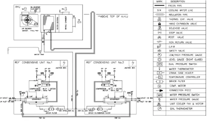
& discharge - ea R404A-Piping Diagram
그림 2 참조 Refrigeration Unit
그림 3 참조 Air Handling Unit
그림 4 참조 Ventilation system
표 6 참조 Air Duct system
(1) Duct의 단면적이 0.02 m2을 초과하는 경우에 는 A구역이나 B구역을 통과하는 Deck나
[그림 2] R 404 A Piping Diagram
[그림 3] Refrigeration Unit
[그림 4] Air Handling Unit
NO Q'ty LOCATION FUNCTION AIR VOLUME MOTOR OutPut m
3/min mmAq
E-1 1 W/P Laundary (Main Dk.) Exhaust 7.5 25 0.6
E-1 1 W/P Toilet(Forecastle Dk.) Exhaust 6.33 25 0.6
E-1 1 Toilet(Bridge&Nav.b.Dk.) Exhaust 5.83 25 0.6
E-2 1 Main Deck Store(Port) Supply 8.67 20 0.6
E-2 1 Deck(Paint) Store(Stbd) Exhaust 5.33 20 0.4
E-3 1 Co2 Room Exhaust 4.17 12 0.6
E-4 1 Dry( Laundary Room) Exhaust 10 20 0.6
E-5 1 Bosun Store Exhaust 12.5 20 0.4
w-6 1 Gallery Exhaust 26.67 15 0.4
w-7 1 Hospital Exhaust 5 40 0.4
S-8 1 Gallery Supply 13.3 20 0.4
S-10 1 Engine Room Supply 750 55 15
S-11 1 Engine Room Supply 750 55 15
S-12 1 Emergency Generator Room Supply 18 20 0.4
S-13 1 Bow Thruster Room Supply 188.67 20 2.2
S-14 1 Dry Bulk Room Supply 45 20 0.4
S-15 1 Steering Gear Room Supply 75 20 0.75
Total 39.35
<표 6> Ventilation Fan(Supply & Exhaust)
Bulkhead에는 3 mm 이상의 steel plate로 제 작 된 관통piece로 제작 취부한다.
(2) Duct의 단면적이 0.075 m2를 초과하는 경우 A- 60구역을 통과하는 Deck나 Bulkhead에는 4.5 mm steel plate로 제작 된 관통piece의 길 이가 900 mm 이상이어야 하며 불연성 방열재 로 방열 마감 후 Fire damper를 설치한다.
(3) Duct의 단면적이 0.02 m2이하인 경우 A구역을 통과하는 Deck나 Bulkhead에는 3 mm 이상의 steel plate로 제작 된 관통 piece의 길이가 200 mm 이상으로 제작 취부한다.
(4) 모든 Duct의 포기치수는 내면 치수를 기준하 며 Duct의 설치높이를 표기하는 H는 원형 Duct의 경우에는 Deck나 Bulkhead로부터 원 형 Duct의 center부분까지의 치수를 말하며 장 방형 Duct의 경우에는 Deck나 Bulkhead로부 터 장방형 Duct의 밑면까지의 치수를 말한다.
(5) 본 Duct 도면에는 장방형Duct의 재질은 Galvanized iron sheet로 선정하고 Galvanized iron sheet의 두께는 0.8 mm ~ 1.2 mm로 선정 한다.
(6) Water tight 구조에 설치되는 Duct는 10 mm 두께의 steel을 사용하고 A-O class의 Duct는 6 mm 두께로 한다. (표 7 참조)
(7) 장방형 Duct의 외부방열은 25 mm 두께의 Thermal insulation재로 방열한 후 Aluminium Foil로 Taping한다.
(8) 장방형 Duct의 연결은 Angle Bar Flange로 한다.(표 8 참조)
(9) Air Terminal의 취출 공기량은 설계 공기량의 90% 이상이어야 한다.
(10) Duct의 support와 Hanger는 steel Angle을 사용한다.(표 9 참조)
(11) 그 외 Duct의 제작 취부 방법 등은 선박용
LONGER SIDE OF DUCT (MM) THICKNESS OF STEEL SHEET (GAUGE)
0 ~ 150 22 (0.8) GALVANIZED STEEL SHEET
151 ~ 300 20 (1.0) GALVANIZED STEEL SHEET
301 ~ 450 18 (1.2) GALVANIZED STEEL SHEET
451 ~ 750 16 (1.5) GALVANIZED STEEL SHEET
751 ~ 900 14 (2.0) GALVANIZED STEEL SHEET
901 ~ 1500 10 (3.0) MILD STEEL PLATE
ABOVE 1501 7 (4.5) MILD STEEL PLATE
<표 7> Duct의 두께
LONGER SIDE OF
DUCT (MM) FLANGE SIZE (ANGLE BAR/FLAT BAR)
0 ~ 300 L20 × 20 × 3t
301 ~ 450
L25 × 25 × 3t451 ~ 750 L25 × 25 × 3t 751 ~ 1200 L38 × 38 × 3t
1201 ~ L50 × 4t
<표 8> Duct Hanger <표 9> Duct Support / Hanger
LONGER SIDE OR
DIA. OF DUCT (MM) DUCTING SUPPORT MATERIAL MAX.
SPACING 0 ~ 300 L20 × 20× 3t C/W TRIANGLE
DOUBLAR PLATE 50× 50× 6t 3000 301 ~ 750 L32× 32× 4t C/W TRIANGLE
DOUBLAR PLATE 75× 75× 6t 2400 751 ~ 1500 L50× 50× 6t C/W TRIANGLE
DOUBLAR PLATE 100× 100× 8t 1800 1501 ~ L75× 75× 6t C/W TRIANGLE
DOUBLAR PLATE 100× 100× 10t 1800
[그림 5] Air Flow Diagram
Duct 표준 설치 방안에 준하여 시행한다.
AIR DUCT DIAGRAM 그림 5 참조 맺음말
이상과 같이 전장(L.O.A) 75 m의 다목적 선박 (Multi purpose field support vessel)의 HVAC System설계를 전반적으로 소개하였다.
선박을 대상으로 하는 HVAC설계 시에는 선급의 규정, SOLAS(해상인명안전규약), ILO 등에서 규정 하는 Rule에 따라야 하며 그 외 항해구역과 선박의 용도 등을 고려한 HVAC설계가 되어야만 한다.
선박은 이동성, 부양성, 적재성 등의 특수상황을 고려하고 선박의 구조와 특성 등을 잘 이해하여야 만 효과적인 선박의 HVAC설계가 이루어진다.
국내 조선산업의 발전과 함께 국내 HVAC업체가 선박용 냉동 공조 시장에 많이 참여하였으면 하는 바람이다.