Packet Utilization 개념을 이용한 저궤도 위성의 데이터 통신 포맷 설계
T이나영P
*
P, 이진호TP
**
P, 석병석P
***
P
Communication Data Format Design for LEO Satellite with Packet Utilization Standard
Na-young Lee*, Jin-ho Lee** and Byong-Suk Suk***
요 약
저궤도위성의 프로그램 운영의 목적에 따라위성의 탑재체를 외부에서 개발하여 위성 버스에 장착하게 된다.
이때 탑재체의 원격텔레메트리 시스템이 위성버스시스템에 설계된 기존 원격텔레메트리 형태에서 벗어난 새로 운 형태를 가질 경우, 기존 원격텔레메트리 시스템에 이를 쉽게 반영하기 힘들었으며, 위성 전체 원격텔레메트 리 운영 구조가 기형적인 형태를 가지게 되었다. 즉, 기존 원격텔레메트리 구조와 변경된 구조가 동식에 존재 하면서 위성 시험 및 관리, 탑재소프트웨어 개발 면에서 여러 가지 어려움이 제기되었다. 따라서 탑재체의 원 격텔레메트리 시스템의 변경에 유연하게 대응할 수 있는 원격텔레메트리 시스템 개발이 필요하다. 또한 저궤도 위성의 성능이 고도화됨에 따라 텔레메트리 데이터가 크게 증가하여기존의 텔레메트리 운용 시스템에서는 이들 을 효과적으로 수용할 수 없었다. 원격텔레메트리를 전송하는 단위가 고정된 그리드 (Grid) 구조인 텔레메트리 전송 체계는 설계상의 오류 발생 가능성이 크며 설계가 진행됨에 따라 새로운 텔레메트리를 전송받기 위해 그 리드 전체를 변경해야 했다. 그리드 방식에서는 Dump 데이터의 운용 역시 많은 제한을 받았다. 이러한 약점을 보완하기위해 최근 유럽에서 인공위성의 텔레메트리 운용에 이용하고 있는PUS (Packet Utilization Standard) 개념을 검토하여 차세대 저궤도위성의 데이터 처리에 이용하고자 한다. 이 개념을 바탕으로 기존 위성 텔레메 트리 시스템에서는 제한적으로 사용되었던 Dump 데이터 전송 및 Event 운용을 위성상태데이터와 별도로 운영 할 수 있게 설계 하였고, 대량의 위성상태데이터를 효율적으로 운영할 수 있도록 Packet 단위의 위성텔레메트 리 시스템을 설계하였다.
Key Words : communication, LEO satellite, packet, telemetry, CADU
ABSTRACT
The conventional telemetry system of Korean low-earth orbiting satellites has certain limitations in accommodating various missions. As the payload becomes complex, it requires very complicated operational concepts in terms of telemetry. With the current design, the telemetry formats have to be rebuilt whenever new payloads or operation concepts are involved, and many constraints in operation shall be produced due to the lacks of its flexibility. As the capability and performance of a satellite have been improved, the communication structure of the satellite should be improved to gather more telemetry data. For the efficiency of data handling, it is necessary to change the grid based telemetry system in which the downlink interval and types for telemetry was limited. Comparing the fixed data map such as grid type, the packet based telemetry system can be operated as flexible and various types of packet can be designed such as the dump packet and the event packet. The sequence of the packets can be modified or newly defined to manage the massive satellite state of health data. In this paper, a new strategy for the telemetry development partially derived from PUS (Packet Utilization Standard) of European Space Agency, which provides enhanced features for the accommodation of payloads & operational requirements, is presented.
** 한국항공우주연구원 [email protected]
** 한국항공우주연구원 [email protected]
*** 한국항공우주연구원 [email protected]
논문번호 : K3-2-3 , 접수일자 : 2008년 11 월 27일, 최종게재논문통보일자 : 2008 년 12 월 26일
1. Introduction
For a geostationary satellite, the communication speed has no issue as the communication is possible always. For a low-earth orbiting satellite, the contact time is limited as several minutes. So the communication speed should be fast such as 1Mbps (bit per second) to downlink massive satellite data. As following CCSDS protocol, telemetry unit is a 256-byte CADU (channel access data unit). More than 1Mbps, hundreds CADUs are downlink. It can be designed more than 2 real-time CADUs downlink. The number of a real time CADU including data collected at the same time can be designed the satellite system. A grid-based telemetry system is defined by a 212- byte telemetry map for one minor frame (1second) and one major frame which is telemetry format period and has 24 minor frames or 32 minor frames. It is not difficult to manage two grids. But as the number of real-time CADU increases, it is not efficient to handle telemetry downlink sequence using several grids. The fixed grid formats have always the drawback that one can not well react on situations where an increase of telemetry reporting would be necessary during the satellite design phase. It is necessary to design the telemetry downlink system to be flexible and to handle large amounts of telemetry data. The packet-based telemetry system allows variable and flexible telemetry design, however a worst case analysis on the peak telemetry downlink is necessary. It is particularly mandatory for packet utilization standard. Various types of packet can be designed such as dump packet and storage only packet. To process big size dump table, an efficient and easy download scheme is required.
For better failure monitoring, detailed event logs is helpful. For easy test and operation, event logs are needed to be processed and displayed in real- time. In this paper, a packet based telemetry downlink scheme is presented.
Ⅱ. Packet management
1. Packet and Packet Group
A packet has fixed length 212byte. XFigure 1X
shows the CADU and packet relationship.
Figure 1: Packet Definition
Packets can be classified as a real-time packet, a dump packet and a storage-only packet. A real- time packet includes the telemetry data gathered at real-time. A dump packet is used for dump operation. A storage-only packet can be designed to store the real-time gathered data and not to downlink at real-time mode. It can downlink at playback mode. For the real-time packet downlink, the packet management design is necessary.
Packets can be designed to monitor the status of some units or to check specified functions. These packets can be grouped. And also several packet groups can be designed as unit purposes or function purposes. So the default packet group for the essential system state of health data, the extended packet group for the long term interval system telemetry, the attitude orbit control packet group for the actuators, star tracker, gyro and position sensors and the payload packet group for the payload telemetry can be designed. The packet sequence for one packet group defines the packet downlink sequence through one CADU downlink position. When the default packet group includes six packets such as {P1.1, P1.2, P1.3, P1.4, P1.5, P1.6}, the default packet sequence can be defined as {P1.1, P1.2, P1.3, P1.4}. Px.y means ‘x’ is a packet group ID and ‘y’ is a packet ID.
2. Packet Management
The packet sequence can be modified by a ground command. To downlink P1.5 and P1.6, the default packet sequence can be modified to {P1.5, P1.6}. This modified sequence is continued before modified to another packet sequence or changed to another packet order. XFigure 2X shows the packet sequence of the default packet sequence from 9 seconds.
TIME Packet of RT CADU
1sec P1.1
2sec P1.2
3sec P1.3
4sec P1.4
5sec P1.1
6sec P1.2
7sec P1.3
8sec P1.4
9sec P1.5
10sec P1.6
11sec P1.5
12sec P1.6
13sec P1.5
14sec P1.6
Figure 2: Packet Sequence Change
The packet sequence change function is very useful to test some specified units or to make the downlink interval of specified packets fast.
The packet order is the downlink order of several packet group every seconds. It can be defined by the ground command which enables or disables one packet sequence table at one CADU downlink position. XFigure 3X shows three packet sequence tables downlink through the second CADU downlink position during 12 seconds. It is assumed the downlink speed is 4096 bps so two real-time packets can be downlink parallel every second. And the default packet table is assumed to downlink at first CADU downlink position. So the packet order #1 is the default PS (packet sequence) for the first CADU downlink position and the extended PS for the second CADU downlink position and the packet order #2 is the default PS and the BUS0 PS and the packet order
#3 is the default PS and the payload PS.
TIME 1st CADU D/L position 2nd CADU D/L position
1sec Default PS Extended PS
2sec Default PS Extended PS
3sec Default PS Extended PS
4sec Default PS Extended PS
5sec Default PS AOCS PS
6sec Default PS AOCS PS
7sec Default PS AOCS PS
8sec Default PS AOCS PS
9sec Default PS Payload PS
10sec Default PS Payload PS
11sec Default PS Payload PS
12sec Default PS Payload PS
Figure 3: Packet Order Selection
When the downlink speed is 1.5M bps (high rate mode), 732 CADUs can downlink every second. Considering memory storage and
downlink capability, the number of RT CADUs can be designed. When 4 RT CADUs downlink per second, 4 packet group can be selected.
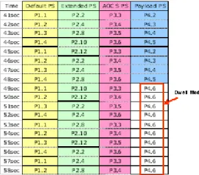
The dwell mode for a single packet is possible by ground command. The dwell mode means one packet downlink during some period defined by a ground command. It is useful to downlink the emergency telemetry or specified purpose telemetry. XFigure 4X shows the P4.6 downlink at 4P
th
P
RT CADU downlink position from 49 sec by the dwell mode command during a high rate mode.
After stopping the dwell mode, the original packet sequence, which was selected at the 4P
th
P CADU downlink position before the dwell command, is started.
Figure 4. Packet Dwell Mode
3. Dump Operation
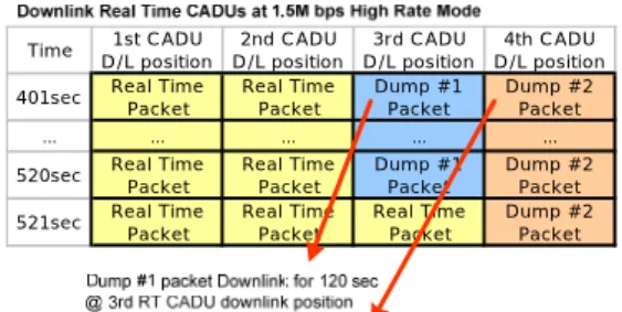
To dump the memory data, a dump packet can be designed. It is necessary to define the dump header for identifying the dump contents and for counting the dump packets. The default packet group, which includes the essential system state of health data, should downlink always so the dump operation is needed to limit. The dump packet can be designed to downlink at the second RT CADU downlink position and the 3P
rd
P or 4P
th
P RT
CADU downlink position. XFigure 5X shows the dump operation when the downlink speed is 1.5M bps. The dump #1 packets downlink during 120 seconds at the 3P
rd
P CADU downlink position and the dump #2 packets downlink during 121
seconds at the 4P
th
P CADU downlink position.
Time 1st CADU D/L position
2nd CADU D/L position
3rd CADU D/L position
4th CADU D/L position 401sec Real Time
Packet Real Time
Packet Dump #1
Packet Dump #2 Packet
… … … … …
520sec Real Time
Packet Real Time
Packet Dump #1
Packet Dump #2 Packet 521sec Real Time
Packet
Real Time Packet
Real Time Packet
Dump #2 Packet
Figure 5: Packet Sequence Change
4. Additional Packet
The additional packet is the packet defined newly on the on-board software by a ground command. It is useful during test phase. The ground station can specify the downlink-cycle of the additional packet. The additional packet ID should be assigned newly. By ground command, the on-board software generates and downlinks the additional packet and then the ground station should decode the raw data in the additional packet as it defined.
5. Event Packet
The purpose of the event logging is to log some events happened during a mission period and a mission upload period. During a mission period, a ground station can contact with satellite or not. In this period, the execution result of a relative time command sequence is needed to log.
The command execution fail information can be defined as one of negative event. During a mission upload period, a ground station can contact with satellite. In this period, the data uploading result and the execution result of uploaded command are needed to log. The format of an event can be defined as an event occurred time, an event ID and an event occurrence counter. The ground station can control the events logging level to record them in the event log table.
When the event level is higher than or same as the logging level, the software logs the event.
When the event level is lower than the logging level, the software does not log the event. The ground station can control the event occurrence level to select how to record the occurrence times.
When the event level is higher than or same as the occurrence level, the software logs the event to another entry. So an event can be logged with the event occurrence counter 1 as it occurring.
When the event level is lower than the occurrence level, the software increments the number of occurrence counter of the event instead of adding another entry for the same event. Events can be designed to downlink every second. The downlink size of event log should be optimized considering the event database. The extended system packet group, in which the long time interval telemetry is assigned, can include the event log area 60byte or less than that size. When the event A occurred continuously 14 times and the event B occurred 2 times, the event A and the event B is logged and downlink through a packet as shown in XFigure 6X. It is assumed the logging level (L.L) is 1 and the occurrence level (O.L) = 3. The level of the event A is less than the O.L so it is logged with the event occurrence counter 14. The level of event B is larger than the O.L so it is logged with the event occurrence counter 1 as it occurring.
Packet Data Data Hex RT Telemetry Data Event 1 Time … Event 1 ID 1111 Event 1 Counter 14 Event 2 Time … Event 2 ID 7777 Event 2 Counter 1 Event 3 Time … Event 3 ID 7777 Event 3 Counter 1 Event ID Level Description
1111 2 Event A
7777 3 Event B
Figure 6: Event Log Downlink
Ⅲ.3. Conclusions
The packet based telemetry system can be operated as flexible and various types of packet can be designed such as the dump packet and the event packet. The sequence of the packets can be modified or newly defined to manage the massive satellite state of health data. In this paper, a new strategy for the telemetry development partially derived from PUS (Packet Utilization Standard) of European Space Agency, which provides enhanced features for the accommodation of payloads & operational requirements, is presented.
참고문헌
[1] Lee N.Y, Lee J.H, Suk B.S, “Design of command and telemetry system for new LEO satellite using PUS concept”, Aerospace Engineering and Technology, Vol.6, no.1, July 2007, pp. 92-96 [2] ESA-ESTEC, PDF, ‘Space Engineering, Ground
Systems and operations – Telemetry and telecommand packet utilization’, pp.1-228.
U저 자 이 나 영(Na-Young Lee)
1999년 2월: 아주대학교 제어계측공학과 졸업 2001년 2월: 한국과학기술원
전기전자 공학부 석사 1996년 3월∼현재: 한국항공
우주연구원
<관심분야> 위성시스템, 위성통신
이 진 호(Jin-Ho Lee)
1990년 2월: 광운대학교 전자 공학과 졸업 1992년 8월: 광운대학교
전기전자공학부 석사 1992년 9월∼현재: 한국항공
우주연구원
<관심분야> 위성시스템, 위성전자
석 병 석(Byong-Suk Suk) 1992년 2월: 경북대학교
전자공학과 졸업 1994년 2월: 경북대학교
전기전자공학부 석사 2006년 2월: 충남대학교
전기전자공학부 박사 1994년∼현재:
한국항공우주연구원
<관심분야> 위성시스템, 위성전자