M
any clinical studies on implant longevity have defined implant success as the attachment of the implant to the osseous tissues and contin- uous support of a prosthesis, sometimes referredto as anchorage function, without regard to per- formance of the completed prosthesis.1,2When the prosthetic components are considered, it is found that considerable maintenance of the compo-
Study of screw loosening in cementation type implant abutment
Bo-Yeon Hwang, DDS, Yung-Soo Kim, DDS, MSD, PhD, MSc(OSU), Chang-Whe Kim, DDS, MSD, PhD
Department of Prosthodontics, College of Dentistry, Seoul National University
The purpose of this study was to compare the screw loosening characteristics of three avail- able cementation type abutments: one-piece cementation type abutment; two-piece cementation type abutment using titanium abutment screw; two-piece cementation type abutment using gold abutment screw.
Two implant supported three-unit superstructures were fabricated using a pair of 3 kinds of abutments for each experimental model.
Cyclic loading was applied on the specimen, and made to stop when the superstructure showed movement over threshold range. The loaded cycle was counted until the machine stopped.
Frequency analysis was done to measure the change of natural frequency before and after the application of cyclic load and to find the effect of screw loosening on the change of natural fre- quency.
The specimen assembly was modeled to perform the finite element analysis to see the distribution of the stress induced by the application of preload over the screw joint and to compare the pat- tern of the distribution of stress induced by the external force with the change of the preload condition.
The following results were obtained:
1. The failure loading cycle of two-piece cementation type abutment using gold screw was sig- nificantly greater than those of the other groups.
2. One-piece cementation type abutment applied to multi-unit restoration case did not show greater resistance to screw loosening compared to two-piece cementation type abutments.
3. Frequency analysis showed decrease in natural frequency when screw loosening occured.
Key Words:
J Korean Acad Prosthodont : Volume 38, Number 6, 2000
nent is necessary to retain their serviceability.
In a 3-year follow-up of 13 patients treated with implant-supported prosthesis, only 6% of implants were lost, but 50% of prostheses became loose and required re-tightening.3In a 1-year recall of 127 free standing fixed prostheses supported by 354 implants, 49% of treated maxillae and 20.8% of treated mandibles exhibited prostheses with loose prosthesis retaining gold screws.4 However, in clinical studies, reports of unretained cement- ed implant prostheses constituted fewer than 5% of the cases.5-8
Considerable advantages can be gained with ce- ment retained restorations, including more pas- sive castings, improved direction of loads, en- hanced esthetics, improved access, progressive loading, reduced crestal bone loss. Possibility of complications, cost, and time are also re- duced.8,9There are two general types of abut- ments for cement retention used in implant pros- thesis: a single unit(or one-piece abutment) and a double unit(or two-piece abutment). The two- piece abutment has one component to engage the antirotational hex of the implant body and another component(abutment screws) to fixate the abut- ment and implant body(or analog) together. The one-piece abutment does not engage the anti- rotational hex but fits flush with the implant platform.
There are two kinds of abutment retaining screw for the two-piece abutment. One is made of titanium and the other of gold alloy. When clin- icians plan to make a cement retained prosthesis, there are total of three kinds of abutment be- tween which they must choose. As of yet, but there have been no scientific study conducted which compares them. Purpose of this study is to com- pare the failure load cycle of screw joints of the three abutments.
MATERIAL AND METHODS
1. Cyclic loading test
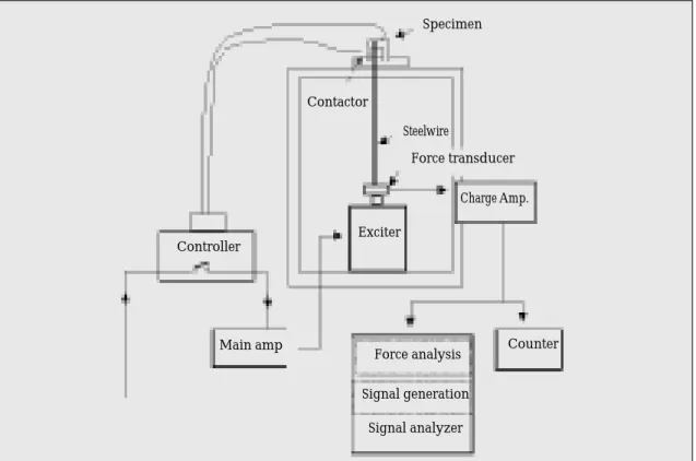
An ‘Exciter’(MB Dynamics, USA), which is mainly used in vibration studies, was used as a cyclic loading instrument. The exciter was lo- cated at the bottom and a steel wire was connected to a sample mounted on a jig for the effect of load- ing only when the wire was under tensile force.
A force transducer(B&K, Denmark) was located between the exciter and the steel wire to measure the quantity of the tensile force placed on the wire.
The signal from the force transducer was trans- mitted into signal analyzer(HP, USA) through a conditioning amplifier(B&K, Denmark). The loading frequency was controlled by the signal an- alyzer and the amplitude by the main amplifier(MB Dynamics, USA). The signal from the force trans- ducer was also imported to the digital counter(Takeda Riken) to count the loading cycle.
An automatic cut-off system was used to de- termine screw failure. Based on the finite element analysis model projections of Sakaguchi and Borgersen,10the asymmetric loading and un- loading cycle would dissipate the screw pre- load. The loss of clamping force would result in movement of the abutment. As the abutment moved, it would contact a metal screw that short- ed out the system and stopped the loading in- strument. The test station was wired to a relay that would trigger the cut-off. The distance between the abutment and the screw tip was set with a gap gauge at the start of the experiment. The screw was then locked in place with a pair of nuts. The 0.26mm distance was selected in the basis of several test runs that indicated predictable screw joint failure at that level of abutment movement.
At failure cut-off, abutment mobility was verified manually by pressing against the abutment. If mo- bility was questionable, the contact screw tip would be recalibrated and the instrument restart- ed until a second failure occurred. This procedure
was repeated until mobility was manually veri- fied.
2. Specimens for cyclic loading tests
The standard 3.75×10 mm external hexagonal Branemark clone implants(ASTM Grade 2 CPT)used in this study were made by AVANA Implant System. Two implants were embedded in a mold with self-curing resin (Vertex) and al- lowed to polymerize overnight.
Because all the abutments were manufactured to the same dimension, an abutment was connected a pair of implants embedded in resin and the whole superstructure was patterned from it repeatedly.
Those patterns were then casted in Ni-Cr al- loy(Verabond). The superstructure has a can- tilever extended perpendicular to the line con- necting centers of the two implants to simulate the effect of buccolingual offset loading. A hole on the cantilever was located horizontally 10mm away from the line connecting centers of two implants and vertically 10 mm above from the platforms of the implants. A steel wire passed through the hole from bottom to top and a small piece of metal plate was attached at the end of wire to generate the loading effect while the wire was under tensile force. While casting the patterns, all the dimension were checked and the fitness between the abut- ment and the superstructure was controlled us- ing a disclosing medium(Fitchecker GC, Japan).
All the abutments were connected to the im- plants and tightened to 10NCm with a mechan- ical torque driver(Tonichi 2FTD, Japan). The abutment-implant complex was then cemented to the superstructure with the Panavia(TC 21) resin cement(KURARAY, Japan). The resin cement was used for its strength and retrievability.
Panavia cement was weak at high temperatures.
Superstructures of two-piece abutments had screw access holes for checking the loosening torque when a sample showed some mobility.
The loading force was set to 100N, and the loading frequency was set to 25Hz.
3. Statistical analysis
A commercial statistical package(SPSS Inc., Chicago, Ill.) was used to determine one-way analysis of variance and to assess statistical dif- ferences in mean values of failure loading cycle among the groups. Two non-parametric test, Kruskal-Wallis and Man-Whitney test were also used because of small sample size.
4. Frequency analysis
Frequency analysis was performed before and after cyclic loading to evaluate the change in natural frequency of a specimen. The exciter generated noise signal and accelerometer(B&K, Denmark) detected acceleration of specimen.
The signal from accelerometer was amplified by conditioning amplifier(B&K, Denmark) and passed into signal analyzer(HP, USA). Two dom- inant natural frequencies were checked and com- pared before and after cyclic loading.
5. FEM study
The I-DEAS(SASI. USA) was the finite ele- ment model designing software used for con- structing the model. During the designing of the models, all these softwares were mounted on Iris Indigo workstations(S.G.I., USA). Models were created to represent the samples used in cyclic loading test. Model 1 represents the sample using one piece cementation type abutment. Model 2 rep- resents the sample using two-piece cementation type abutment with titanium screw, and Model 3 represents the sample using two-piece cemen- tation type abutment with gold screw.
Material properties used in the analysis were based on manufacturer’s specifications and ap- plicable technical data sheets for the specific ma- terials. A modulus of elasticity of 99.3 GPa was
used for the gold-alloy components; 110 GPa was used for the commercially pure(CP) titanium components; 210 GPa for Ni-Cr alloy(super- structure); 1.63 GPa for resin; 1.7 GPa for resin ce- ment. Poisson’s ratio was 0.28 for the metal components and 0.35 for resin and resin cement.
Since the screw was assumed to function within the ealstic range during preload development, yield points and strain hardening curves were not in- cluded.
The preload condition was achieved by speci- fying an initial overlap, or interface, between the contact bodies in the model, taking advantages of several features of the solver(ANSYS, SASI, USA).
Preload was applied to the abutment screw by using a moving rigid surface to displace the api- cal contact surface of the overlapped abutment
screw past the associated bearing surface of the abutment. This placed the abutment screw into a state of axial tension, as the threaded end of the abutment screw is held in place by contact between the abutment screw threads and the mating threads of the implant.
The rigid surface was then released from the screw, which permitted the screw to snap back elas- tically into contact with the abutment. When the bearing surface on the bottom of the abutment screw head contacted the bearing surface on the abutment, the bodies were not allowed to pene- trate, and compression loads developed on the bearing interface, resulting in preloading of the abutment screw.
The same technique was used for one-piece cementation type abutment, but after this, the ti- tanium screw and abutment, initially modeled sep-
Fig. 1.Cyclic loading test system.
Specimen
Force transducer
Force analysis Counter Charge Amp.
Exciter Controller
Main amp
Contactor
Steelwire
Signal generation Signal analyzer
arately, were connected and the gap between them was filled.
An assumed coefficient of friction of 0.4 was in- troduced between all contacting surfaces.
Initial penetration of the screw surface into its seat was established by comparing the re- leased screw length with experimental data(ti- tanium abutment screw: elongation 3.28 ㎛, torque 19.12 Ncm; gold retaining screw: elon- gation 5.6 ㎛, torque 10.22 Ncm).11The penetration distance was adjusted so that the final released screw length matched the experimental results. An
input torque of 10 Ncm, 5 Ncm, 0 Ncm for the re- taining screw was simulated for all the models in order to induce different preload conditions.
After initial preload was applied, compres- sive loading of 100 N force was applied on the same point in each model as was in the cyclic load- ing test.
The maximum principal stress of retaining screw was compared and analysed, taking into ac- count the change of preload conditions of each model. Stress distribution was presented as col- or differences in figures. The separations that occurred between the abutments and implants ac- cording to changes in preload conditions of each model were compared.
RESULTS
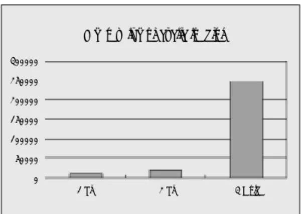
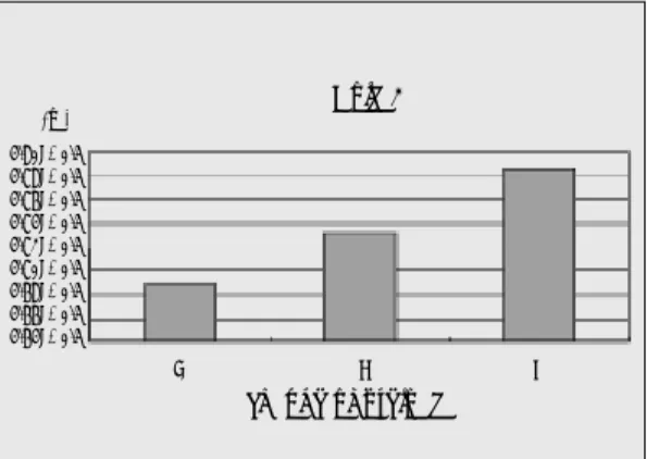
The results of the cyclic loading test are listed in Table Ⅰ. Screw joint failure ranged from 5,792 to over 400,000 cycles.
Screw joint of one piece cementation type abut- ment failed at a mean of 9,612.6 cycles. Screw joint of two piece abutment using titanium screw failed at a mean value of 19,934.4 cycles. When us- ing the gold screw, joint failed at a mean value of 248,967.8
Figure 5 shows the mean value of failure load- ing cycle of each abutment.
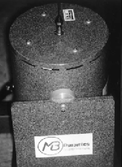
With limited number of samples, and some Fig. 2. Appliances used in cyclic loading test.
Fig. 4.Exciter and force transducer.
Fig. 3.Mounted specimen and connected steel wire.
data apparently not normally distributed, two non- parametric test of differences between means(Kruskal-Wallis test and Mann-Whitney test) and ANOVA were used. Table Ⅱ shows the re- sults of ANOVA, and Table Ⅲ those of Scheffe post-hoc test. Table Ⅳ shows the results of non- parametric tests. All the statistical analysis shows that mean failure cycle of two-piece abutment us- ing gold screw is significantly greater than the oth- er groups.
Fig. 5. Mean value of failure loading cycle.
Mean value of cyclic loading
1 Ti 300000
250000 200000 150000 100000 50000 0
2 Ti 3 Gold
T
Taabbllee ⅢⅢ.. Summary of Scheffe post-hoc comparisons
Scheffe 1 Ti 2 Ti .983
2 Gold* .003
2 Ti 1 Ti .983
2 Gold* .005
2 Gold 1 Ti* .003
2 Ti* .005
T
Taabbllee ⅣⅣ.. Result of Mann-Whitney test
1 Ti - 2 Ti .117
2 Ti - 2 Gold .009
1 Ti - 2 Gold .009
Kruskal Wallis sig: .005 T
Taabbllee ⅠⅠ.. Results of cyclic loading test
Sample 1 9086 17591 50338
Sample 2 9888 35094 205294
Sample 3 9382 21893 189207
Sample 4 10835 5792 400000*
Sample 5 8872 19302 400000*
MEAN 9612.6 19934.4 248967.8
SD 782.48 10482.71 150460.96
(I)group (J)group sig
significance(2-tailed) 1 pc Titanium 2 pc Titanium screw 2 pc Gold screw
T
Taabbllee ⅡⅡ.. Summary of analysis of variance among groups
Between groups 2 1.83E+11 9.15E+10 12.072 .001
Within groups 12 9.10E+10 7.58E+09
Total 14 2.74E+11
Source DF Sum of squres Mean squares F Sig.
T
Taabbllee ⅤⅤ.. Result of natural frequency analysis
loading loading loading loading loading loading
Natural 7.860 7.456 7.488 7.424 7.680 7.296
frequency(Hz) 8.288 8.064 8.096 8.032 8.704 8.032
1 Ti 2 Ti 2 Gold
before after before after before after
T
Taabbllee ⅥⅥ.. Principal stress on node #23324(Pa)
Ti 1 0.35236E+08 0.78080E+09 0.78046E+09 0.78011E+09
Ti 2 0.25217E+08 0.77609E+09 0.77666E+09 0.77674E+09
Gold 2 0.91387E+08 0.94297E+09 0.79193E+09 0.79438E+09
A: preload was applied only
B: external force(100N) was applied under preload C: external force(100N) was applied under 1/2 preload D: external force(100N) only was applied
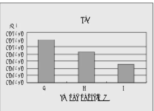
Fig. 6.Graph of principal stress on node #23324 of one piece cementation type abutment when external force was applied with the change of preload.
Fig. 7.Graph of principal stress on node #23324 of two piece cementation type abutment using titanium screw when external force was applied with the change of preload.
Ti 1
change of preload
B (Pa)
7.81E+0.8 7.81E+0.8 7.81E+0.8 7.80E+0.8 7.80E+0.8 7.80E+0.8 7.80E+0.8 7.80E+0.8
(Pa) 7.77E+0.8 7.77E+0.8 7.76E+0.8 7.76E+0.8 7.76E+0.8 7.76E+0.8 7.76E+0.8
C D B C D
change of preload Ti 2
A B C D
1. Frequency analysis
Table Ⅴ shows the result of frequency analysis.
All the specimen tested showed decrease in nat- ural frequency after loading.
2. FEM study
Figure 16 shows the external view of the mod- el generated.
Graphical display of results of the FEM study contained abutment, abutment screw, and implant.
Other components were excluded for the simplicity
of display. The value of tensile stress on node num- ber of #23324(located in the screw neck at the op- posite side of force application just below the screw head) was compared in each model with the change in preload conditions. The distance between the node #3007 and #43007 was measured and compared with the change in preload condi- tions.
Model 1(one-piece cementation type abut- ment)
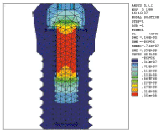
Figure 17 shows the distribution of stress induced solely by preload. Tensile stress was distributed on the area between the head and threads of the screw. Compressive stress was induced between
Fig. 9.Separation between abutment and implant(one- piece titanium abutment).
Fig. 10.Separation between abutment and implant(two- piece cementation type abutment using titanium screw).
T
Taabbllee ⅦⅦ.. Distance between node #3007 and #43007(m)
Ti 1 5.05549E-05 5.05649E-05 5.05649E-05
Ti 2 5.09525E-05 5.10924E-05 5.12835E-05
Gold 2 4.68907E-05 4.7321E-05 4.78617E-05
B: external force(100N) was applied under preload C: external force(100N) was applied under 1/2 preload D: external force(100N) only was applied
Fig. 8.Graph of principal stress on node #23324 of two piece cementation type abutment using gold screw when external force was applied with the change of pre- load.
Gold 2
change of preload
B (Pa)
1.00E+0.9 9.50E+0.8 9.00E+0.8 8.50E+0.8 8.00E+0.8 7.50E+0.8 7.00E+0.8
C D
Ti 1 Ti 2
change of preload
B (m)
5.06E-0.5 5.06E-0.5 5.06E-0.5 5.06E-0.5 5.06E-0.5 5.06E-0.5 5.06E-0.5 5.06E-0.5 5.06E-0.5 5.06E-0.5
(m) 5.14E-0.5 5.13E-0.5 5.12E-0.5 5.11E-0.5 5.10E-0.5 5.09E-0.5 5.08E-0.5 5.07E-0.5
C D
change of preload
B C D
B C D
the bottom of abutment and the top surface of im- plant.
Application of external force (100N) on the cantilever area induced additional tensile stress on the opposite side of screw, and additional compressive force on the abutment and implant interface on the same side (Fig. 18�20).
The distribution of stress with the change in pre- load was similar and the separation occurring be- tween the abutment and fixture can be seen in the pictures. The exact values of induced stress and the displacement of bottom of abutment was different with the change in preload conditions.
Table 6 shows the induced tensile stress on the ref- erence node #23324. The values were compared in Figure 6. The stress decreased slightly as the pre- load decreased. The displacement of abutment was compared in Table Ⅶ.
Model 2(two-piece cementation type abut- ment using titanium screw)
Preload stress is shown in Figure 21 Compressive stress between the bottom of screw head and abutment can be seen. No significant change in dis- tribution of stress induced by external force (100N) could be found (Fig. 22�24). But the val- ue of tensile stress on node #23324 increased as the preload decreased (Table Ⅵ, Fig. 7). The dis-
placement of abutment increased as the preload decreased (Table Ⅶ, Fig. 10).
Model 3(two-piece cementation type abut- ment using gold screw)
Preload stress is shown in Figure 25 Compressive stress between the bottom of screw head and abutment can be seen. No significant change in dis- tribution of stress induced by external force (100N) could be found (Fig. 26�28). Value of tensile stress on node #23324 showed some dif- ference in distribution pattern. The stress under the initial preload condition was the greatest, but the stress without preload was greater than the stress with half of initial preload (Table Ⅵ, Fig.
8). The displacement of abutment increased as the preload decreased (Table Ⅶ, Fig. 11).
DISCUSSION
The primary objective of tightening any screw joint is to generate adquate clamping force to keep the component parts together. This is ac- complished by applying an appropriate amount of tightening torque to the screw to generate the maximum preload(elongation of the screw) below its fatigue limits. When the total load applied to the screw(preload and external load) exceeds the fatigue parameters, the ability to clamp the com- ponents together decreases dramatically. Screw joint failure as described by Bickford12occurs in two stages. The first consists of external functional loading that gradually and effectively erodes the preload. The greater the joint preload, the greater the resistance to loosening, and the more stable the joint. Eventually, the critical load exceeds the screw joint preload and it becomes unsta- ble. In the second stage of screw loosening, the ex- ternal load rapidly erodes the remaining pre- load and results in vibration and micromove- ment that leads to the screw baking out. Other fac- tors, such as the screw’s fatigue characteristics and component misfit, also affect preload and screw Fig. 11.Separation between abutment and implant(two-
piece cementation type abutment using gold screw).
Gold 2
change of preload
B (m)
4.80E+0.5 4.78E+0.5 4.76E+0.5 4.74E+0.5 4.72E+0.5 4.70E+0.5 4.68E+0.5 4.66E+0.5 4.64E+0.5
C D
joint stability.13,14When component parts fit together perfectly, optimal preload can be achieved. When incorrect fit exists or the joint is contaminated by debris, the achievable preload is significantly reduced.15Furthermore, when preload is used to bring the ill-fitting mating together, fatigue pro- tection is lost, because all external loads will in- crease screw tension instead of being dissipated in the component stack.16
Each abutment was tightened to 10 Ncm to produce some preload. Manufacturer recom- mended torque was 20 Ncm for titanium abut- ments, and 32 Ncm for gold abutments. With those tightening torques, mean preload was 468.2 N using gold alloy screws and 318.5N with tita- nium screws.17 Occlusal forces on adult teeth and prosthese have been recorded by numer- ous investigators.18-23Craig reported forces on molar, premolar, and incisor teeth ranging from 390 to 880 N, 453 N, and 222 N, respectively.24 Richter reported maximum vertical bite forces on molar implants of 121.1±69.6 N during func- tion and 53.8±21.9 during clenching activity.25
A 100 N load was arbitrarily selected. In cal- culating the force experienced by abutment re- taining screw, not only the external force exerted on the sample but also the leverage effect should be considered.
10 N force was loaded horizontally and verti- cally 10mm away from the center on the top of im- plants, so a bigger force was expected to be exerted on the retaining screws.
In this experiment, smaller clamping force and larger joint separating force than those found in clinical situations were applied to get the results earlier.
In the cyclic loading test, two-piece abutment with gold screw showed results significantly different from the other two abutments.
This differs from Misch’s opinion.26Misch claimed that when one-piece cementation type abutment was used in multi-unit case, the su-
perstructure splinting the abutments would pre- vent the screw from loosening.
This shows that screw loosening happens not from the turning but from the elongation of screws. In the case of one-piece abutment, after su- perstructure was removed, there was no resistance to loosening the abutment manually.
The possible reasons why one-piece abutment was loosened easily are listed below.
1. The magnitude of preload applied was small- er than those of other groups.
2. There was no structure to distract the external force.
Preload is induced in a screw when torque is ap- plied during tightening. The screw elongates, placing the shank and threads in tension. The elas- tic recovery of the screw creates the clamping force that pulls the prosthesis and implant together.
Tightening torque is also opposed by frictional forces under the head of the screw and in the mat- ing threads.27Resisting torque induced by frictional force against tightening torque is proportional to the distance from the center of screw. There is dif- ference in size of screw head between one piece abutment and two piece abutment, and also in the area of contact under the screw head. Statistically, as the size of screw head increases, so dose the sum of the frictional forces resisting the tightening of the screw. Though, under the same magnitude of compression and coefficient of friction, same amount of frictional force is induced, the one piece abutment contacts the platform of implant far from the center of the screw. Consequently, the resisting torque is increased(Torque=radius×
force).
When an asymmetric external force is applied on the superstructure, stress would be concentrated at the edge of the fixture shoulder on the side where larger force is applied, and a separation would be noted between the abutment and fixture on the side opposite the applied load.11Under large clamping force, negligible amount of gap would
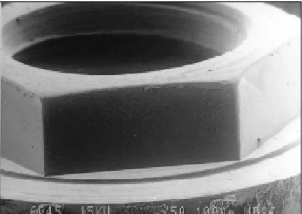
Fig. 12.SEM of edge in the external hex of implant con- nected to the two piece cementation type abutment(×
50).
Fig. 13.SEM of edge in the external hex of implant con- nected to the two piece cementation type abutment(×
200).
Fig. 14.SEM of edge in the external hex of implant con- nected to the one piece cementation type abutment(×
50).
Fig. 15. SEM of edge in the external hex of implant con- nected to the one piece cementation type abutment(×
200).
be present, but as preload is eroded away, the size of gap opening will increase. With some degree of abutment movement, in two-piece abutments, contact occurs between the internal hex in the abut- ment and the external hex on the fixture top.
When there is contact between the mating surfaces, the external force is in part dissipated by these structures. In one-piece abutment, there is no internal hex to engage the external hex. The screw part in one-piece abutment must bear all the offset loading. This is supported by the scan- ning electron microscopic(SEM) views of the
implant external hexagonal (Fig. 12�15). The implant hexagonal flat demonstrates compression of its surface irregularities, evidence of abrasion, and scuffing.
The resistance of two-piece abutment using gold screw to screw loosening was significantly superior. It is supposedly due to the lower frictional coefficient between gold and titanium(Ti-Au μ
=.15/Ti-Ti μ=.5)28leading to greater preload.
The FEM study provides insight into the be- havior of the abutment screw relative to the abutment and fixture during load application. As
the screw is tightened, tensile stress develops in the body of the screw, from the neck imme- diately beneath the head through the threaded ar- eas. This stress is transferred to the threaded portions of the implant. Immediately after tight- ening the abutment screw, there are compressive stress at the screw head-abutment seat inter- face(two piece abutment). In case of the one- piece abutment, there are compressive stress at the bottom of abutment-the top of implant inter- face. As asymmetric loads are applied at the cantilever area, the abutment-superstructure complex displaces in the direction of the load.
Compressive stresses become concentrated at the corner of the abutment interface as the abut- ment and superstructure rotates in a counter- clockwise direction. On the opposite side, there is separation between the abutment and the im- plant on the right side, on both the vertical and hor- izontal surfaces.
When the loads are cycled on the superstructure, there is a counter-clockwise rotation from the load application, followed by a clockwise re- covery as the loads are removed. The asymmet- ric cyclic loading and unloading on the base of the abutment screw head contributes to the loosen- ing of the screw. After screw has loosened, further load application results in increased rotation of abutment. Table Ⅶ shows increased displace-
ment of the abutment with the decrease in preload.
Junker and Wallace29have shown that for ec- centrically loaded threaded joints, the greater the preload applied(up to a maximum of the yield load for the screw), the longer will be the fa- tigue life of that screw. In the Model 2(two-piece cementation type abutment using titanium screw), the tensile stress measured at node #23324 showed increase as the applied preload decreased.
The maximum tensile stress experienced by the screw also showed the same result. Similar pat- tern was also observed in Model 3(two piece ce- mentation type abutment using gold screw); the stress was greater in condition D(without preload) than condition C(with half of the preload).
To ensure the tendancy of tensile stress, addi- tional study was done. The preload was in- creased two times in Model 2, and two and three times in Model 3. The result showed strong ten- dancy of decrease in tensile stress with the increase of preload.
The value of Model 3 in condition B was found to be an erroneous result.
Though the same preload was applied, the screw in the Model 1 experienced higher ten- sile stress than Model 2 when external force was applied. This is supposed to be due to the dif- ference in structure between these abutments.
The result of cyclic loading test showed greater re- T
Taabbllee ⅧⅧ.. Principal stress on node #23324(Pa)
Ti 1 0.78080E+09 0.78046E+09 0.78011E+09
Ti 2 0.77446E+09 0.77609E+09 0.77666E+09 0.77674E+09
Gold 2 0.75639E+09 0.775210E+09 0.94297E+09 0.79193E+09 0.79438E+09 3B : external force(100 N) was applied under 3×preload
2B : external force(100 N) was applied under 2×preload B : external force(100 N) was applied under preload C : external force(100 N) was applied under 1/2 preload D : external force(100 N) only was applied
3B 2B B C D
sistance in the two-piece titanium abutment us- ing titanium screw than in the one-piece titanium abutment. This may be another reason for larger failure loading cycle of two-piece abutment.
The nature of the geometry of dental implant components dictates the need for modeling the be- havior with a nonlinear contact analysis. Previous studies have been limited to linear elastic analy- sis, which do not allow for plastic deformation or for separation of contacting surfaces. The contact analysis demonstrates separations at the abutment- implant interface and abutment-abutment screw interface, which are consistent with those found in an in vitro simulation in a servohydraulic ro- bot testing instrument
Every mechanical system has one or more
“natural frequencies”with which it vibrates in the absence of external forces. The natural frequen- cy is dependent on the stiffness and mass. The ide- alized mathematical model gives the following for- mula for the natural frequency:
stiffness Natural frequncy = ─────
mass
In frequency analysis, some decrease in natural frequency was observed after screw loosening, and it is due to the decrease in stiffness of screw joints. Through this experiment, it was found that natural frequency analysis could be used to detect loss of preload in screw joints, that is to detect loosening in screw joints. In cases of mul- ti-unit restorations, detecting screw loosening in vitro is almost impossible when adequate tightening torque is applied. In the pilot study, the specimen tested showed no screw loosening over 10,000,000 cycles(two-piece abutment using gold screw tightened to 32 Ncm, with loading of 100N and loading frequency of 1 KHz). Further study is needed to know if natural frequency analysis can be applied with adequate sensitivi- ty in such cases.
CONCLUSIONS
1. The failure loading cycle of two-piece ce- mentation type abutment using gold screw was significantly greater than those of the other groups.
2. One-piece cementation type abutment ap- plied to multi-unit restoration case did not show greater resistance to screw loosening compared to two-piece cementation type abut- ments.
3. Frequency analysis showed decreases in nat- ural frequency when screw loosening occured.
REFERENCES
1. Adell R, Lekholm U, Rockler B, Branemark P-I. A 15-year study of osseointegrated implants in the treatment of the edentulous jaw. Int J Oral Surg 1981;10:387-416.
2. Patrick D, Zosky J,Lubar R,Buchs A. The longi- tudinal efficacy of Core-Vent dental implants in par- tially edentulous patients. In: Laney WR, Tolman DE(eds). Tissue Integration in Oral, Orthopedic, and Maxillofacial Reconstruction. Chicago: Quintessence, 1992:341-349.
3. Gregory M, Murphy WM, Scott J, Watson CJ, Reeve PE. A clinical study of the Branemark den- tal implant system. Br Dent J 1990;168:18-23.
4. Jemt T, Linden B, Lekholm U. Failures and com- plications in 127 consecutively placed fixed partial prostheses supported by Branemark implants:
From prosthetic treatment to first annual checkup.
Int J Oral Maxillofac Implants 1992;7:40-44.
5. McKinney RV Jr, editor: Endosteal dental im- plants, St Louis, 1991, Mosby.
6. Misch CE: Implant registry of graduates from the Misch Implant Institute, Dearborn, Mich, 1991.
7. Singer A, Serfaty V: Cement retained implant supported fixed partial dentures-a 6 month to 3 year follow up, Int J Oral Maxillofac Implants 11:645-649, 1996.
8. Misch CE: Screw-retained versus cement retained implant supported prostheses, Pract Perio Aesth Dent 7(9):15-18, 1995.
9. Misch CE: Principles for cement retained fixed implant prosthodontics in contemporary implant dentistry, pp651-668, St Louise, 1993, Mosby.
10. Roland L. Sakaguchi, Svenn E. Borgersen Nonlinear finite element contact analysis of dental implant components Int J Oral Maxillofac Implants 1993;8:655-661.
11. Haak JE, Sakaguchi RL, Sun T, Coffey JP.
Determination of preload stress in dental implant screws. J Dent Res 1994;73(special issue):202.
12. Bickford JH. An introduction to the Design and Behavior of Bolted joints. New York: Marcel Dekker, 1995:515-564.
13. Patterson EA, Johns RB. Theoretical analysis of the fatigue life of fixture screws in osseointegrated den- tal implants. Int J Oral Maxillofac Implants 1992;7:26-33.
14. Burguete RL, Johns RB, King T, Patterson EA.
Tightening characteristics for screw joints in os- seointegrated dental implants. JPD 1994;71:592-599.
15. Carr A, Brunski J, Labishak J, Bagley B. Preload com- parison between as-received and cast-to-implant cylinders. JDR 1993;72(suppl 1);190-195.
16. Juvinall RC. Fundamentals of Machine Component Design. New York: John Wiley&sons, 193:200- 206.
17. James E. Haack, Roland L. Sakaguchim, Ting Sun, James P. Coffey. Elongation and preload stress in dental implant abutment screws. Int J Oral Maxillofac Implants 1995;10:529-36.
18. Meng TR, Rugh JD. Biting force on overdentures and conventional denture patients[abstract 716]. J Dent Res 1983;62:249.
19. Ralph WJ. The effects of dental treatment on biting force. J Prosthet Dent 1979:41:143.
20. Carlsson GE, Haraldson T. Functional response.
In:Branemark P-I, Zarb GA, Albrektsson T(eds).
Tissue-Integrated prostheses. Chicago: Quintessence 1986:156-163.
21. Graf H. Occlusal forces during function.
In:Occlusion:Research on Form and Function.
Ann Arbor, MI: Univ of Michigan Press, 1975:90-
92.
22. Harrison A, Lewis TT. The development of abra- sion testing machine. J Biomed Mater Res 1975;9:341- 344.
23. Blamphin CN, Bradfield TR, Jobbins B, Fisher J, Watson CJ, Redfern EJ. A simple instrument for the measurement of maximum occlusal force in human dentition. Proc Inst Mech Eng 1990;204:129-131.
24. Craig RG. Restorative Dental Materials, ed 6. St Louis: Mosby, 1980:60-61.
25. Richter EJ. In vivo vertical forces on implants.
Int J Oral Maxillofac Implants 1995;10:99-108.
26. Carl E. Misch. Contemporary Implant Dentistry.(2ed) Mosby; 1999.
27. James E. Haak, Roland L. Sakaguchi, Tin Sun, James P. Coffey. Elongation and preload stress in dental implant abutment screws. Int J Oral Maxillofac Implants 1995;10:529-36.
28. Bowden FP, Tabor D. The friction and lubrica- tion of solids. Oxford: Oxford University Press, 1950.
29. Junker GH, Wallace PW: The bolted joint: Economy of design through improved analysis and assem- bly methods. Proc Inst Mech Eng[H] 1984;1988:255- 266.
Reprint request to:
DR. YUNG-SOO KIM
DEPT. OF PROSTHOODNTICS, COLLEGE OF DENTISTRY, SEOUL NATIONAL UNIV.
28-1, YEOMGUN-DONG, CHONGNO-GU, SEOUL , 110-749, KOREA Tel: +82-2-760-2661 Fax: +82-2-760-3860
EXPLANATION OF PHOTOGRAPHY
Fig. 16. External oblique view of the 3D FEM model(Model 1,2,3).
Fig. 17. Maximal principal stress of model 1 with preload.
Fig. 18. Maximal principal stress of model 1 under external force(100N) with preload.
Fig. 19. Maximal principal stress of model 1 under external force(100N) with half of preload.
Fig. 20. Maximal principal stress of model 1 under external force(100N) without preload.
Fig. 21. Maximal principal stress of model 2 with preload.
Fig. 22. Maximal principal stress of model 2 under external force(100N) with preload.
Fig. 23. Maximal principal stress of model 2 under external force(100N) with half of preload.
Fig. 24. Maximal principal stress of model 2 under external force(100N) without preload.
Fig. 25. Maximal principal stress of model 3 with preload.
Fig. 26. Maximal principal stress of model 3 under external force(100N) with preload.
Fig. 27. Maximal principal stress of model 3 under external force(100N) with half of preload.
Fig. 28. Maximal principal stress of model 3 under external force(100N) without preload.
FIGURE ①①
Fig. 16 Fig. 17
Fig. 18 Fig. 19
Fig. 20 Fig. 21
FIGURE ②②
Fig. 22 Fig. 23
Fig. 24 Fig. 25
Fig. 26 Fig. 27
Fig. 28