Se-Il Suk, MD
Seoul Spine Institute, Inje University Sanggye Paik Hospital, Seoul, Korea
Copyright © 2011 by The Korean Orthopaedic Association
This is an Open Access article distributed under the terms of the Creative Commons Attribution Non-Commercial License (http://creativecommons.org/licenses/by-nc/3.0) which permits unrestricted non-commercial use, distribution, and reproduction in any medium, provided the original work is properly cited.
Clinics in Orthopedic Surgery • pISSN 2005-291X eISSN 2005-4408 Received May 6, 2010; Accepted June 10, 2010
Correspondence to: Se-Il Suk, MD
Seoul Spine Institute, Inje University Sanggye Paik Hospital, 761-1 Sanggye-dong, Nowon-gu, Seoul 139-707, Korea
Tel: +82-2-3392-1100, Fax: +82-2-3392-1101 E-mail: [email protected]
The pedicle is a power nucleus of the vertebra and offers a secure grip of all 3 columns. Pedicle screw instrumentation has advan- tages of rigid fixation with improved three-dimensional (3D) correction and it is accepted as a reliable method with a high margin of safety. Accurate placement of the pedicle screws is important to reduce possible irreversible complications. Many methods of screw insertion have been reported. The author has been using the K-wire method coupled with the intraoperative single pos- teroanterior and lateral radiographs, which is the most safe, accurate and fast method. Identification of the curve patterns and determining the fusion levels are very important. The ideal classification of adolescent idiopathic scoli osis should address the all patterns, predict the extent of accurate fusion and have good inter/intraobserver reliability. My classification system matches with the ideal classification system, and it is simple and easy to learn; and my classification system has only 4 structural curve patterns and each curve has 2 types. Scoliosis is a 3D deformity; the coronal and sagittal curves can be corrected with rod rotation, and ro- tational deformity has to be corrected with direct vertebral rotation (DVR). Rod derotation and DVR are true methods of 3D defor- mity correction with shorter fusion and improved correction of both the fused and unfused curves, and this is accomplished using pedicle screw fixation. The direction of DVR is very important and it should be opposite to the direction of the rotational deformity of the vertebra. A rigid rod has to be used to prevent rod bend-out during the derotation and DVR.
Keywords: Adolescent idiopathic scoliosis, Pedicle screw instrumentation, Pedicle screw insertion technique, Fusion level, Di- rect vertebral rotation
The Harrington instrument was one of the earliest forms of spinal instrumentation, and it uses concave distraction and convex compression for the correction of the scolio- sis.1,2) Although considerable coronal plane correction was obtained with the Harrington instrument, it was ineffec- tive for correcting the rotational component and it caused flattening of the sagittal contour.
In the early 1980s, Cotrel et al.3) introduced Cotrel-
Dubousset (CD) segmental spinal instrumentation. This system was designed to address not only the frontal plane deformity, but also the sagittal plane deformity. It was dif- ferent from the conventional segmental fixation in that the correction of the deformity is attempted primarily by derotation of the concave rod, which converts the frontal curvature into a sagittal curvature.4) By addressing the de- formity in three dimensions, CD instrumentation enabled superior correction of the coronal plane Cobb angle com- pared with that obtained by using Harrington instrumen- tation. It also restored the sagittal curvature.5-7) CD hooks have the advantages of easy loading and they minimize the chance of root injuries, but the procedures for proper in- sertion of the hooks are complicated and time consuming, and as the laminar hooks are placed in the spinal canal,
there is the inherent danger of cord injury, especially for the convex apical hook that is pushed inward by the rod.
There are also problems of unloading and the hooks pull- ing out during the introduction of the rod and rotation maneuvers.8)
Pedicle screw fixation in adolescent idiopathic scoli- osis (AIS) offers enhanced correction of three-dimensional (3D) deformity and preservation of the motion segments by reducing the number of levels that are fused.9,10) The au- thor has been using pedicle screws for the management of deformities since 1988. Initially, pedicle screws were used in the thoracolumbar spine where the pedicles were large and easily visualized. With the success in the thoracolum- bar spine, pedicle screws were gradually used in the more proximal levels.11,12) In the earlier period, the screws were not placed segmentally, that is to say, following the stan- dard CD hook pattern.5) The results of nonsegmental ped- icle screw fixation were superior to that of hooks, but there were often complications due to pullout of the screws or breakage of pedicles during the derotation maneuver. This problem was solved by adding more screws to the concave side of the deformity and to disperse the stress among an increased number of screws.13) Nonsegmental pedicle screw fixation does not offer rigid fixation and segmental control of the deformity in rigid and severe curves, yet it can be effectively used in mild and flexible curves.
Pedicle screws in the thoracic spine were not widely used because of the fear of causing permanent neurologi- cal injuries, despite the superb biomechanical advantages of pedicle screws over the other forms of spinal instru- mentation.9) The incidence of misplaced thoracic pedicle screws ranges from 1.5-25.0%. The incidence of screw- related neurological complication is 0-0.9%.10,12,14-16) The most important step to prevent complications is confirma- tion of an accurate pedicle screw starting point within the confines of the pedicle. Many other methods have been reported since this author first started using the K-wire method of pedicle screw insertion.9,16) We believe that the K-wire method is the safest, most accurate and rapid method of pedicle screw insertion. Thoracic pedicle screw instrumentation for AIS is now well accepted as an excel- lent, reliable and safe method of correcting deformity.
THE K-WIRE METHOD OF PEDICLE SCREW INSERTION
9,17)Incision and Exposure
A standard posterior midline incision is made from the upper end of the spinous process two levels above the uppermost instrumented pedicle to the lower end of the
lamina of the lowest instrumented vertebra. The proximal incision should be long enough to allow convergence of the pedicle screws in the uppermost vertebra. The spine is exposed to the tip of the transverse processes bilaterally, with staying strictly subperiosteal to reduce bleeding.
Facetectomy
The facets included in the fusion are destroyed by inferior facetectomy and removal of the articular cartilage to pro- mote intra-articular arthrodesis. Care should be taken not to disturb the adjacent facets that are not in the fusion area to prevent instability and precocious degenerative change.
Determining the Pedicle Entry Points
The presumed pedicle entry points are decorticated with a rongeur to facilitate the insertion of the guide pins. In the thoracic spine, the presumed pedicle entry point is located at the junction of the lateral margin of the facet joint and the upper 1/3 of the transverse process in the upper tho- racic spine, and at the superior margin of the transverse process in the middle thoracic spine and the middle of the transverse process in the lower thoracic spine, like that in the lumbar spine. Then guide pins are inserted at a depth of 1 cm through the exposed cancellous bone at the pre- sumed pedicle entry point. Different sizes of K-wire are used on both sides. To facilitate radiograph interpretation, the guide pins are directed along the axis of the pedicle in the frontal and sagittal planes. After the guide pins are in place at the planned pedicle screw sites, intraopera- tive posteroanterior (PA) and lateral roentgenograms are taken to determine the association between the presumed entry point and the ideal entry point identified on the ra- diograph. This helps determine the ideal direction of the screws. Taking the transverse angle of the pedicles into consideration, the ideal pedicle entry point (IPEP) in a neutrally rotated vertebra is at the junction of 1) a line par- allel to the vertebral end plates and that bisects the pedicle and 2) the lateral margin of the pedicle ring shadow on a PA X-ray. In the rotated vertebrae, the IPEP of the pedicles on the side of the rotation (the convex side of the scoliosis) moves more medially, whereas the IPEP on the opposite side (the concave side) moves more laterally with increas- ing vertebral rotation (Fig. 1).
Hole Preparation
After determining the position of the IPEP and the direc- tion of the ideal pedicle paths relative to the guide pin, the pedicle is entered through the starting point with an awl and then a small drill (60% of the outer pedicle diam- eter)18) or a small curette. It is important to keep in mind
the normal transverse angle of the pedicles for the particu- lar level to prevent inadvertent pedicle perforation. Then the hole is checked with a blunt-ended probe. A safe entry into the pedicle is confirmed when the probe meets bony resistance in all directions and cancellous bone at the tip, meaning that the hole is surrounded by bone.
Screw Insertion
The screw has to be turned with gentle force so that the screw follows the predrilled path. The ideal screw diam- eter is about 80% of the pedicle diameter.19,20) However, in pediatric patients oversized screws up to 115% of the inside pedicle diameter may be inserted without causing a significant decrease in the screw’s holding power because of the plasticity of the pedicular cortex.16,20,21) The ideal screw length is about 70% penetration of the vertebral body, as seen on a lateral radiograph, to avoid complica- tions of screw overpenetration. Screws are inserted on every segment on the correction sides (thoracic concave and lumbar convex) and every second or third on the sup- port sides (thoracic convex and lumbar concave). In severe rigid scoliosis, bilateral segmental insertion can be applied to increase the rigidity of the fixation, and especially in the lumbar levels.
DEFORMITY CORRECTION
17)Correction Side Rod Insertion (Concave in Thoracic and Convex in Lumbar)
After inserting the screws on both the concave and the convex sides is complete, a rod contoured to have a slight exaggeration of the normal sagittal contour of the instru- mented segment is inserted into the correction (concave) side.13) Insertion of the rod may be difficult when there is a large discrepancy between the contour of the vertebral
column and that of the rod. This may be facilitated by us- ing rod introducers or sequentially closing the screw caps while rotating the rod to fit the contour of the vertebral column. Long arm reduction screws may be used effec- tively. For long curves that span both the thoracic and the lumbar region, either a long rod spanning the entire cor- rection side or shorter rods spanning each of the curves may be used. For a double thoracic curve, separate cor- rection of each curve is carried out with short rods on the respective concave sides. When the plan is to perform separate correction of individual structural curves, remove a pedicle screw at the junction of the rods to make room for rod connectors. Following the rod insertion, the eye bolts are loosely inserted over the screws.
Rod Derotation
Using clamps or rod holders, the correction rod is rotated 90 degrees to transform the scoliosis into a kyphosis at the thoracic spine and into a lordosis at lumbar spine and restore the sagittal profile in the corrected position. Cor- rection of the deformity is performed solely by derotation without any additional compression or distraction. As considerable straightening of the contoured rod occurs during the process of derotation, it is advantageous to use large-bore stiff rods with exaggeration of the normal sag- ittal profile.13) When two rods are used on one side, they should be connected by means of a connector prior to the rod rotation maneuver.
Support Side Rod Insertion
As the rod is just supportive, convex in the thoracic and concave in the lumbar, the rod is bent to conform to the shape of the corrected curve and the rod is placed in situ without forceful manipulation. In double thoracic curves using a four-rod correction technique, the support rods Fig. 1. (A) Intraoperative posteroanterior and lateral radiographs after K-wires are inserted. (B) Magnified T8-10. Exact pedicle entry points are marked.
are connected to the correction rods by means of connectors.
Direct Vertebral Rotation (DVR)
After the rod derotation to correct the coronal and sagittal curves, DVR is performed to correct the rotational defor- mity. The surgical procedure of DVR is described at the end of this paper.
Transverse Connection
Two transverse connectors are used in the proximal and the distal parts of the longitudinal members to enhance the torsional stiffness of the pedicle screw construct.
SUK CLASSIFICATION AND THE FUSION LEVELS IN AIS
16,22,23)The location of spinal fusion is the most important single factor that influences the postoperative result of surgical correction for idiopathic scoliosis. Inappropriately choos- ing the extent of fusion may result in under or overcor- rection of the major and compensatory curves, and this may result in failure to stabilize the index curve, it can ag- gravate the unfused curve and cause trunk imbalance and decompensation.24) To minimize such complications, the conventionally accepted guidelines for fusion recommend including all the vertebra in the major curve and extend- ing the fusion down to the “stable” vertebra to place the fusion mass on a stable basis.24,25) The previous guidelines for fusion to the stable vertebra for AIS were established through the Harrington experience and they have now be- came obsolete with the advent of newer segmental spinal instruments.26) Pedicle screw fixation effectively shortens the extent of distal fusion by improved 3D deformity cor- rection with rod derotation and DVR.
In AIS, identifying the curve patterns and determin- ing the fusion levels are very important factors for defor- mity correction, avoiding trunk imbalance and saving motion segments. The ideal classification of AIS should address all patterns, predict accurate limits of the defor- mity and the extent of fusion, and it should have good re- producibility and good inter/intraobserver reliability. The author’s classification matches the ideal classification as it is simple, easy to learn and it can be applied with pedicle screw instrumentation.
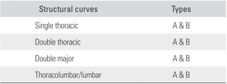
This classification defines four structural curves:
single thoracic, double thoracic, double major and thora- columbar/lumbar. Each structural curve has two types; A and B (Table 1).
Single Thoracic Curve
The thoracic curve is larger than the lumbar curve and the thoracic curve is more than 40o. If the lumbar curve is more than 40o, then the thoracic curve should be 5o greater than the lumbar curve and the apical vertebra ro- tation of the lumbar spine should be less than Nash-Moe grade II. A selective thoracic fusion is appropriate in the single thoracic curve (Fig. 2).9,23) After a selective thoracic fusion, the results, regardless of the rotational status of the lumbar curve, were satisfactory with straightening of the lumbar curves and good balance.25) A selective thoracic fusion means fuse to the proximal neutral vertebra (NV) and to the distal NV. It is important to determine the exact distal fusion level and the NV is an important factor for determining the fusion level. There are two types, A and B, depending on the relation between the end vertebra (EV) and the NV. When the preoperative EV and the NV show no more than a one-level gap difference (type A), the curve could be fused down to the NV. When the NV is the same as the EV, fusion can be stopped at the EV. If the NV is located 2-3 levels more distally than the EV (type B), then fusion has to go down one more level distal than the type A or NV-1. In this way, the motion of one or two seg- ments can be saved, compared to fusion extending to the stable vertebra.
Double Thoracic Curve
It is important to determine the indication for fusing the proximal thoracic curve when correcting double tho- racic scoliosis with segmental instrumentation. Failure to recognize a significant proximal thoracic curve often results in postoperative shoulder asymmetry due to rela- tive overcorrection of the lower thoracic curve.22,27-29) With segmental instrumentation that enhances the correction of the instrumented curve, the double thoracic curve pattern that needs fusion of both the proximal and the distal tho- racic curves is redefined as follows.30) Idiopathic thoracic scoliosis with a proximal thoracic curve of more than 30o and a level or elevated left shoulder should be considered a double thoracic curve pattern and it should be treated
Table 1. Classification of Adolescent Idiopathic Scoli osis
Structural curves Types
Single thoracic A & B
Double thoracic A & B
Double major A & B
Thoracolumbar/lumbar A & B
by fusing both the proximal and distal curves when using segmental instrumentation. The distal fusion levels are same as those in a single thoracic curve, whether it is the type A or B.
Double Major Curve
The double major curve is defined as follows. The lumbar curve is larger than the thoracic curve. The lumbar curve is more than 40o and the thoracic curve is more than 30o, and the thoracic curve is less than 5o larger than the lum- bar curve and the apical vertebra rotation of the lumbar is more than grade II. In these cases, both the thoracic and lumbar curves have to be fused. It is important to save the distal fusion level. There are types A and B, depending on
the findings of the lumbar bending films. A type A curve is when L3 crosses the mid-sacral line in right bending and the L3 rotation is less than grade II in left bending, and this curve can be fused to the EV, which is usually L3, and not L4. When L3 does not cross the mid-sacral line in right bending and the L3 rotation is more than grade II in left bending, then fuse to the EV + 1~2 or EV - 1, which is usually L4 (Fig. 3).
Thoracolumbar and Lumbar Curve
The thoracolumbar and lumbar (TL/L) curve is a curve that is more than 40o and the thoracic curve is less than 30o. In this case, only the TL/L curve needs to be fused.
There are types A and B for the distal fusion levels de- Fig. 2. Single thoracic adolescent idio- pathic scoliosis is defined as a thoracic curve that is more than 40° and is larger than the lumbar curve. A selective thoracic fusion from the proximal neutral vertebra (NV) to the distal NV is recommended. There are two types, A and B, depending on the relation between the distal end vertebra (EV) and the NV. (A) In type A, the NV is located at the EV + 1 or the same level, and can be fused to the NV. (B) In type B, the NV is located at the EV + 3 and must be fused to the NV - 1 or the EV + 2.
Fig. 3. The double major curve is defined as a lumbar curve greater than 40o and larger the thoracic curve. The thoracic cuve is more than 30° and both curves have to be fused. There are two types, A and B. In type A, L3 crosses the mid sacral line and the rotation is less than grade 2 in the bending film. In type B, L3 does not cross the mid sacral line and the rotation is more than grade 2 in the bending film.
pending on the lumbar bending films. This is the same as in a double major curve. The curve can be fused to L3, not L4, saving one distal motion segment, when the preopera- tive L3 rotation is less than grade II and the translation is across the center sacral vertical line (CSVL) on the bend- ing radiographs (type A). If not, fusion has to be extended to L4 (type B) (Fig. 4).
DIRECT VERTEBRAL ROTATION
31)There are two forces induced by rod derotation. First, the vector of “rod derotation” is directed posteriorly and medially. This force corrects both the coronal and sagit- tal plane deformities, but not that in the transverse plane.
Second, the rod is also rotated about 90o on its own axis during rod derotation. This may affect the vertebral rota- tion in scoliosis. In the cases with severe or rigid scoliosis, for example, there is friction between the rod and the pedicle screws during rod derotation. This rotational force tends to increase the rotational deformity. If there is no friction between the rod and the screws, then the screws will glide on the rod. In this situation, the rotational de- formity may be corrected depending on the angle between the pedicle screws and the vector of rod derotation. This might be similar to rod derotation in flexible mild curves.
Derotation in flexible curves is promoted by the posterior force vector by the rod moving posterior during derota- tion, which thus pulls the concave side posterior while the opposite side moves to a lesser distance. The effect of rod
derotation on the rotational correction is negligible be- cause there always exists some amount of friction between the screws and the rod during rod derotation. Clinically, the rotational correction obtained by rod derotation is probably from the translation of the vertebra.
The concept of the DVR is simple. That is to say, it is the correction of vertebral rotation by application of a force directed posteriorly in the direction opposite to that of the deformity. The pedicle screw enters the pedicle pos- teriorly and it traverses to the anterior vertebral body. This makes it possible to transmit the rotational force to the en- tire vertebral body and so correct the rotational deformity.
Other posterior instrumentations such as hooks or wire systems cannot deliver sufficient torque anteriorly to en- able vertebral rotation because the axis of fixation is pos- terior to that of vertebral rotation. The torque is applied to the pedicle screws using long screw derotators on both the concave and convex sides of the curve. The DVR corrects the intervertebral rotation, which means it enables a 3D correction in scoliosis surgery. The direction of the DVR is important and it should be opposite to that of the vertebral rotation. In the right thoracic curve, the apical and juxta- apical vertebrae are rotated clockwise in the transverse plane. The direction of DVR must be opposite to the rota- tional deformity and counterclockwise to the rotation in the transverse plane. The uppermost one or two vertebra have to be derotated opposite the direction of the thoracic DVR. Yet for the lowermost one or two screws, the direc- tion of DVR depends on the rotation of vertebra in the Fig. 4. The thoracolumbar and lumbar (TL/L) curve is defined as a TL/L curve more than 40° with a thoracic curve less than 30°. The TL/L curve only should be fused. The two types, A and B, depend on whether the L3 crosses mid sacral line and the rotation is more or less than grade II, in bending radiographs. This is the same as in the double major curve.
compensatory lumbar curve.
DVR Procedure
1. Insert the pedicle screws at each segment on the correc- tion sides (thoracic concave) and every second or third segment on the support side (thoracic convex) of the curves.
2. Rotate the precontoured rod on the correction side (counter-clockwise) without any compression or dis- traction.
3. Insert the screw derotators (2-3 derotators) onto the pedicle screws of the juxta-apical vertebrae on the con- cave side, or both the concave and the convex sides.
4. After the rod derotation and maintaining the rod dero- tation, rotate the screw derotators to the opposite direc- tion (clockwise) of the rod derotation.
5. Rotate the uppermost pedicle screws to the opposite di- rection of the thoracic DVR.
6. Rotate the lowermost pedicle screws depending on the unfused lumbar curve.
7. After locking the concave rod in the corrected position, a rod contoured to the corrected curve is placed on the convex side and it is locked in situ.
The transverse rotation can be easily corrected using long lever-arm screw derotators, 2-3 screws at the same time. This will distribute the rotational torque among several pedicles to help prevent pedicle breakage. There is little chance of canal intrusion due to pedicle breakage
during the DVR when the screws are inserted correctly because the medial wall of the pedicle is three times stron- ger than the lateral wall.
Direction of DVR Single thoracic curve
The direction of DVR on the juxta-apical vertebrae is op- posite to the rotation of the vertebrae in the transverse plane. During or after the rod is derotated 90o counter- clockwise, the DVR on the juxta-apical screws should be rotated clockwise. The direction of the DVR of the proxi- mal 1 or 2 vertebrae has to be opposite to the direction of the thoracic DVR for obtaining correct shoulder balance.
For the lowermost one or two screws, there are two op- tions depending on the distal uninstrumented lumbar curve. These screws have an important role in regulating the compensatory lumbar curve. In a thoracic concave, whether single or double concave, when the preoperative compensatory lumbar curve crosses the CSVL with a rota- tion (type A), the two lowermost screws should be rotated opposite to the direction of the thoracic DVR, that is, in the direction of lessening the lumbar rotation (Fig. 5).
One reason for this is that the remnant thoracic rotational deformity inhibits the ultimate rotational correction in the lumbar curve, even though a significant amount of lumbar rotation is spontaneously corrected. In this situation, the lumbar rotation is improved by rotating the lowermost screws to the opposite direction of the thoracic DVR. On Fig. 5. (A) A 15-year-old girl with a single thoracic adolescent idiopathic scoliosis, type A, in which the neutral vertebra (NV) is the same as the end vertebra (EV). The distal fusion level is T12 (NV) and the direction of the direct vertebral rotation (DVR) of the distal NV is the opposite direction compared with the thoracic DVR. (B) The patient is treated with the rod derotation and DVR, and the postoperative radiographs show a well-balanced spine.
the other hand, when the distal vertebrae are rotated in the same direction as that of the thoracic rotation, like in a type B thoracic curve, the DVR has to be rotated the same direction of the thoracic DVR, and with more forceful DVR when the lumbar rotation is more severe (Fig. 6).
Double thoracic curve
The DVR direction of both the proximal and the distal thoracic curves in the double thoracic curves are the same
as that in a single thoracic curve. The distal fusion levels are also the same as that in the single thoracic curve, type A and B (Fig. 7).
Double major curve
The DVR direction of the thoracic curve is the same as that in a single thoracic curve and the lumbar curve is ro- tated toward the opposite direction of the thoracic DVR.
The distal fusion levels are at L3 in type A and L4 in type B
Fig. 6. (A) A 14-year-old girl with a single thoracic adolescent idiopathic scoliosis, type B, in which the neutral vertebra (NV) is located at the end vertebra (EV) + 3. The distal fusion level is the NV - 1 (L3) and the direction of the direct vertebral rotation (DVR) of the distal NV is the same direction compared with the thoracic DVR. (B) The patient is treated with the rod derotation and the DVR method.
Fig. 7. (A) A 13-year-old girl with a double thoracic adolescent idiopathic scoliosis. The distal fusion level is the neutral vertebra (NV), which is L1, and the direction of the direct vertebral rotation (DVR) is the opposite direction compared to the thoracic DVR. (B) Both thoracic curves are fused with four rods, rod derotation and DVR. (C) The preoperative unequal shoulder height is well corrected postoperatively. EV: end vertebra.
double major curve (Figs. 10 and 11). With this principle, the TL/L curve can be fused short, like in the anterior in- strumentation.
ity to restore the thoracic kyphosis. Many methods have been reported for pedicle screw insertion. Since 1988 we have found that the safest and most effective pedicle screw insertion to be the K-wire method coupled with using the
Fig. 8. (A) A 13-year-old girl with a double major curve of adolescent idiopathic scoliosis. The direct vertebral rotation (DVR) direction of the lumbar curve is the opposite to the direction of the thoracic DVR. (B) Bending radiographs show that L3 crosses the mid sacral line and L3 rotation is less than grade II (type A). This is fused to the neutral vertebra (NV) - 1 (L3). (C) Both thoracic and lumbar curves are treated with two rods, translation and DVR.
EV: end vertebra.
Fig. 9. (A) A 17-year-old girl with a double major curve, type B. The direct vertebral rotation (DVR) direction of the lumbar curve is opposite to the direction of the thoracic DVR. (B) Bending radiographs show that L3 does not cross the mid sacral line and L3 rotation is more than grade II (type B), which is fused to the neutral vertebra (NV; L4). (C) The patient is treated with two rods, rod derotation and DVR. EV: end vertebra.
intraoperative single PA and lateral radiographs.
It is imperative to understand each of the curve patterns and the fusion level of the AIS to obtain satisfac- tory curve correction. The Suk classification of the AIS has four structural curves and each has two types (A and B) that define the distal fusion levels. This classification is straight forward, it predicts accurate limits of the defor- mity and the extent of fusion, it is reproducible and it has good inter/intraobserver reliability. Idiopathic scoliosis is a complex 3D deformity in the coronal, sagittal and rota-
tional planes. Rod derotation can correct the coronal and sagittal curves well, but it has little effect on the rotational correction (Table 2). DVR corrects the vertebral rotational deformity, which is accomplished by using the pedicle screw fixation, because it is the only instrumentation sys- tem that effectively uses the pedicle and the vertebral body as the anchors for the fixation. The direction of DVR is very important, and this should be opposite the rotational deformity of the vertebra.
Fig. 10. (A) A 13-year-old girl with a thoracolumbar curve with fusion of the thoracolumbar curve only. The direction of direct vertebral rotation (DVR) is the same in both the thoracic and the lumbar curve. (B) Bending radiographs show L3 crosses the mid sacral line and L3 rotation is less than grade II (type A) on bending film. (C) The patient is fused to the neutral vertebra (NV)-1 (L3) with rod derotation (S bended rod) and DVR. EV: end vertebra.
Fig. 11. (A) A 15-year-old girl with a thoracolumbar curve. (B) Bending radiographs show that L3 does not cross the mid sacral line and L3 rotation is more than grade II (type B). (C) The patient is fused to the neutral vertebra (NV; L4) with rod derotation (S bended rod) and direct vertebral rotation. EV:
end vertebra.
Lumbar DM TL/L
A B
Bending L3: cross CSL Rotation < grade II Bending L3: not cross CSL Rotation > grade II
L3 L4
DVR: direct vertebral rotation, AIS: adolescent idiopathic scoliosis, NV: neutral vertebra, EV: end vertebra, OD: opposite direction, SD: same direction, DM:
double major, TL/L: thoracolumbar and lumbar, CSL: center sacral line.
ACKNOWLEDGEMENTS
The author thanks William P. Haake, MD who reviewed the article and polished the English writing.
REFERENCES
1. Harrington PR. Treatment of scoliosis: correction and inter- nal fixation by spine instrumentation. J Bone Joint Surg Am.
1962;44(4):591-610.
2. Goldstein LA. Treatment of idiopathic scoliosis by Har- rington instrumentation and fusion with fresh autogenous iliac bone grafts. J Bone Joint Surg Am. 1969;51(2):209-22.
3. Cotrel Y, Dubousset J, Guillaumat M. New universal in- strumentation in spinal surgery. Clin Orthop Relat Res.
1988;227:10-23.
4. Bridwell KH, McAllister JW, Betz RR, Huss G, Clancy M, Schoenecker PL. Coronal decompensation produced by Co- trel-Dubousset “derotation” maneuver for idiopathic right thoracic scoliosis. Spine (Phila Pa 1976). 1991;16(7):769-77.
5. Shufflebarger HL, Clark CE. Fusion levels and hook patterns in thoracic scoliosis with Cotrel-Dubousset instrumenta- tion. Spine (Phila Pa 1976). 1990;15(9):916-20.
6. Suk SI, Lee CK, Chung SS. Comparison of Zielke ventral derotation system and Cotrel-Dubousset instrumentation in the treatment of idiopathic lumbar and thoracolumbar scoliosis. Spine (Phila Pa 1976). 1994;19(4):419-29.
7. Labelle H, Dansereau J, Bellefleur C, de Guise J, Rivard CH, Poitras B. Peroperative three-dimensional correction of idiopathic scoliosis with the Cotrel-Dubousset procedure.
Spine (Phila Pa 1976). 1995;20(12):1406-9.
8. Suk SI, Lee CK, Min HJ, Cho KH, Oh JH. Comparison of Cotrel-Dubousset pedicle screws and hooks in the treat- ment of idiopathic scoliosis. Int Orthop. 1994;18(6):341-6.
9. Suk SI, Lee CK, Kim WJ, Chung YJ, Park YB. Segmental pedicle screw fixation in the treatment of thoracic idiopathic scoliosis. Spine (Phila Pa 1976). 1995;20(12):1399-405.
10. Liljenqvist UR, Halm HF, Link TM. Pedicle screw instru-
mentation of the thoracic spine in idiopathic scoliosis. Spine (Phila Pa 1976). 1997;22(19):2239-45.
11. Roy-Camille R, Saillant G, Mazel C. Internal fixation of the lumbar spine with pedicle screw plating. Clin Orthop Relat Res. 1986;(203):7-17.
12. Brown CA, Lenke LG, Bridwell KH, Geideman WM, Hasan SA, Blanke K. Complications of pediatric thoraco- lumbar and lumbar pedicle screws. Spine (Phila Pa 1976).
1998;23(14):1566-71.
13. Suk SI, Kim WJ, Kim JH, Lee SM. Restoration of thoracic kyphosis in the hypokyphotic spine: a comparison between multiple-hook and segmental pedicle screw fixation in ado- lescent idiopathic scoliosis. J Spinal Disord. 1999;12(6):489- 95.
14. Esses SI, Sachs BL, Dreyzin V. Complications associated with the technique of pedicle screw fixation: a selected survey of ABS members. Spine (Phila Pa 1976). 1993;18(15):2231-8.
15. Lonstein JE, Denis F, Perra JH, Pinto MR, Smith MD, Win- ter RB. Complications associated with pedicle screws. J Bone Joint Surg Am. 1999;81(11):1519-28.
16. Suk SI, Kim WJ, Lee SM, Kim JH, Chung ER. Thoracic pedicle screw fixation in spinal deformities: are they really safe? Spine (Phila Pa 1976). 2001;26(18):2049-57.
17. Brown CW, ed. Spinal instrumentation techniques. Rose- mont, IL: Scoliosis Research Society; 1998.
18. Suk SI, Cha SI, Lee CK, et al. A study on the pullout strength of pedicle screws in relation to the size of the drill holes and inserted screws. Paper presented at: The 30th Annual Meet- ing of the Scoliosis Research Society; 1995 Sep 13-16; Ashe- ville, NC, USA.
19. Zindrick MR, Wiltse LL, Doornik A, et al. Analysis of the
morphometric characteristics of the thoracic and lumbar pedicles. Spine (Phila Pa 1976). 1987;12(2):160-6.
20. Misenhimer GR, Peek RD, Wiltse LL, Rothman SL, Widell EH Jr. Anatomic analysis of pedicle cortical and cancellous diameter as related to screw size. Spine (Phila Pa 1976).
1989;14(4):367-72.
21. Suk SI, Lee JH. A study of the diameter and change of the vertebral pedicle after screw insertion. Paper presented at:
Third International Meeting SIROT; 1994 Oct; Boston, MA, USA.
22. Suk SI, Kim WJ, Lee CS, et al. Indications of proximal tho- racic curve fusion in thoracic adolescent idiopathic scoliosis:
recognition and treatment of double thoracic curve pattern in adolescent idiopathic scoliosis treated with segmental in- strumentation. Spine (Phila Pa 1976). 2000;25(18):2342-9.
23. Suk SI, Lee SM, Chung ER, Kim JH, Kim WJ, Sohn HM.
Determination of distal fusion level with segmental pedicle screw fixation in single thoracic idiopathic scoliosis. Spine (Phila Pa 1976). 2003;28(5):484-91.
24. Margulies JY, Floman Y, Robin GC, et al. An algorithm for selection of instrumentation levels in scoliosis. Eur Spine J.
1998;7(2):88-94.
25. King HA, Moe JH, Bradford DS, Winter RB. The selection of fusion levels in thoracic idiopathic scoliosis. J Bone Joint Surg Am. 1983;65(9):1302-13.
26. Lenke LG, Betz RR, Bridwell KH, Harms J, Clements DH, Lowe TG. Spontaneous lumbar curve coronal correc- tion after selective anterior or posterior thoracic fusion in adolescent idiopathic scoliosis. Spine (Phila Pa 1976).
1999;24(16):1663-71.
27. Lee CK, Denis F, Winter RB, Lonstein JE. Analysis of the upper thoracic curve in surgically treated idiopathic sco- liosis: a new concept of the double thoracic curve pattern.
Spine (Phila Pa 1976). 1993;18(12):1599-608.
28. Lenke LG, Bridwell KH, O’Brien MF, Baldus C, Blanke K. Recognition and treatment of the proximal thoracic curve in adolescent idiopathic scoliosis treated with Cotrel-Dubousset instrumentation. Spine (Phila Pa 1976).
1994;19(14):1589-97.
29. Winter RB, Denis F. The King V curve pattern: its analy- sis and surgical treatment. Orthop Clin North Am.
1994;25(2):353-62.
30. Arlet V, Marchesi D, Papin P, Aebi M. Decompensation fol- lowing scoliosis surgery: treatment by decreasing the cor- rection of the main thoracic curve or “letting the spine go”.
Eur Spine J. 2000;9(2):156-60.
31. Lee SM, Suk SI, Chung ER. Direct vertebral rotation: a new technique of three-dimensional deformity correction with segmental pedicle screw fixation in adolescent idiopathic scoliosis. Spine (Phila Pa 1976). 2004;29(3):343-9.