Recent Issues in
Musculoskeletal Anatomy Research and Correlation with MRI
근골격 해부학의 최신 지견 및 자기공명영상 소견
Hyerim Park, MD , Joon-Yong Jung, MD*
Department of Radiology, Seoul St. Mary’s Hospital, College of Medicine, The Catholic University of Korea, Seoul, Korea
MRI is a valuable imaging technique for the evaluation of intraarticular diseases. Accurate inter- pretation of joint MRI necessitates sound knowledge of anatomy. In the field of joint anatomy, in addition to the discovery of new structures, previously reported joint components of unex- plained function are also detected. In this review, joint anatomy researched actively over the last decade is discussed. Joint components including the rotator cable and the superior capsule of the shoulder, posterolateral corner and the anterolateral ligament complex of the knee, and the distal tibiofibular syndesmosis of the ankle joint are introduced and correlated with their MRI features.
Index terms Anatomy; Knee; Shoulder; Ankle; Magnetic Resonance Imaging
서론
3 Tesla 이상의 고자장 MRI 기기의 보급과 다채널 코일의 발전으로 예전에는 확인하기 어 려웠던 관절의 작은 해부학적 구조물들을 확인할 수 있게 되었다. 또한 삼차원 고속스핀에코 영상은 원하는 단면으로 재구성이 가능하여, 복잡한 주행을 가진 구조에 대한 영상의학적 이 해가 더욱 높아지고 있다. 본 종설에서는 MRI 영상으로 확인 가능한 관절의 구조물들 중 최 근 십여 년간 연구가 이루어지고, 임상적으로도 관심이 증가하고 있는 해부학에 대한 연구 결과를 소개하고, MRI 영상에서 이를 확인해 보고자 한다. 여기서 소개하는 구조물들의 대 부분은 새로이 발견되거나 정립된 것들로 해부학적 용어의 한글화가 이루어지지 않아 가급 적 영문 명칭을 그대로 사용하였다.
Received September 10, 2019 Revised December 18, 2019 Accepted January 7, 2020
*Corresponding author Joon-Yong Jung, MD Department of Radiology, Seoul St. Mary’s Hospital, College of Medicine,
The Catholic University of Korea, 222 Banpo-daero, Seocho-gu, Seoul 06591, Korea.
Tel 82-2-2258-6254 Fax 82-2-599-6771
E-mail jjdragon112@gmail.com This is an Open Access article distributed under the terms of the Creative Commons Attribu- tion Non-Commercial License (https://creativecommons.org/
licenses/by-nc/4.0) which permits unrestricted non-commercial use, distribution, and reproduc- tion in any medium, provided the original work is properly cited.
ORCID iDs Hyerim Park https://
orcid.org/0000-0002-1879-8802 Joon-Yong Jung
https://
orcid.org/0000-0002-6909-0919
Posterolateral Corner of the Knee
Posterolateral corner (이하 PLC)는 복잡한 해부학적 구조로 인해 영상에서 확인이 어려운 구 조물이었으나, 최근 고자장 영상기기의 보급과 해부학-영상의학 연관성 연구들의 뒷받침으로, MRI 영상에서 각각의 구조물들을 확인할 수 있게 되었다. PLC의 주된 역할은 슬관절의 후외측에 서의 안정화이며, 부수적으로 내반변형(varus angulation), 후방전위(posterior translation), 외 전(external rotation)을 제한하는 역할을 한다(1).
PLC는 posterolateral ligamentous complex 또는 arcuate ligament complex 등으로 다양하 게 불려왔다(2, 3). 하지만 arcuate ligament complex는 arcuate ligament, fabellofibular liga- ment (이하 FFL), 그리고 popliteofibular ligament (이하 PFL)만을 포함하는 개념이다(4). 많은 연구에서 PLC는 외측측부인대(lateral collateral ligament; 이하 LCL), popliteus tendon, PFL 그 리고 arcuate ligament와 FFL을 포함한 후외측 관절막(posterolateral capsule) 까지를 아우르는 개념으로 정의하고 있다(5, 6).
외측측부인대
외측측부인대(LCL)는 외측 대퇴과(lateral femoral condyle)에서 비골두(fibular head)를 향하 여 주행하게 된다. 근위 부착부는 다양하나 대개는 관절선에서부터 상방 2 cm 정도에서 외측 상과 (lateral epicondyle)의 뒤쪽에 부착하게 된다(7). 거기에서부터 비골두까지 후하방으로 주행하게 된다. 원위 부착부인 비골두에서는 FFL과 arcuate ligament보다 바깥쪽에 붙는다(Fig. 1A) (7, 8).
외측측부인대와 대퇴 이두건(biceps femoris tendon)은 공통건(conjoined tendon)을 형성하 게 되며 이 두 구조물 사이에 LCL-biceps femoris bursa가 존재하는데, MRI 영상에서는 잘 보이 지 않는다(7).
외측측부인대의 길이는 무릎 신전시에 대략 60 mm로 측정되며 평균 너비는 3~5 mm 정도이다(9, 10). 정상 외측측부인대는 균일한 저신호강도로 보이며 직선으로 주행한다(Fig. 2). 외측측부인대은 다른 PLC 구조물들 중에서 내반변형(varus angulation)을 막는데 있어 가장 주된 역할을 한다(10).
Popliteus Muscle-Tendon-Ligament Complex
Popliteus muscle-tendon-ligament complex는 popliteus tendon과 PFL, popliteomeniscal
fascicle로 구성되어 있다(11). Popliteus tendon은 외측 대퇴과(lateral femoral condyle)에서 부
착하며, arcuate ligament, FFL의 안쪽으로 주행하며 popliteal hiatus를 통하여 관절 내부에서 외
부로 빠져나가 근위부 경골의 후내측에 근조직의 형태로 기시하게 된다(Fig. 2) (9). Popliteus ten-
don은 모든 MR 시퀀스에서 저신호강도로 보이나, 에코시간(echo time)이 짧은 시퀀스에서는 마
쪽에 부착하게 된다(Figs. 1A, 3A, 3B) (12). PFL은 PLC의 손상이 없는 대부분의 슬관절 MRI 영상 에서 확인이 가능하며, 짧은 저신호강도의 띠로 보이게 된다. 시상영상에서 확인이 용이하며, 경우 에 따라 축상영상에서도 확인할 수 있다.
Popliteomeniscal fascicle은 popliteus tendon과 관절낭(joint capsule), 외측 반월연골(later- al meniscus)의 후각을 연결하는 섬유띠로 슬관절 신전시에 외측 반월연골의 과도한 움직임을 제 한하는 역할을 한다(13). Popliteomeniscal fascicle의 정확한 개수에는 논란이 있지만 시상영상 에서 posterosuperior popliteomeniscal fascicle과 anteroinferior popliteomeniscal fascicle은 비교적 일관되게 확인이 가능하다(Fig. 3C). Posterosuperior popliteomeniscal fascicle의 손상 은 외측 반월연골의 후각부 열상을 예측하는데 도움을 줄 수 있는데, 약 79~100%의 양성예측도를 보인다고 알려져 있다(14).
Arcuate and Fabellofibular Ligaments
Arcuate ligament의 정의는 문헌마다 다른 의미로 사용되어 혼란을 가져왔는데, 일부 저자들 은 FFL 및 PFL을 기술하는데 arcuate ligament라는 용어를 사용하였으나, 현재는 독립된 인대라 기보다는 부분적으로 두꺼워진 후외측 관절막으로 보는 것이 일반적이다(7, 15). Y자 형태를 이루 는 두 개의 분지로 구성되는데, 외측 분지는 관절막을 따라 상방으로 진행하게 되며, arcuate limb 이라고도 불리는 내측 분지는 상내측으로 진행하여 popliteus tendon의 뒤쪽을 지나 후방 관절막 과 합쳐지게 된다(16). PFL보다는 약간 위쪽에서 보다 표층에 위치하며, 비골 경상돌기에서는 PFL
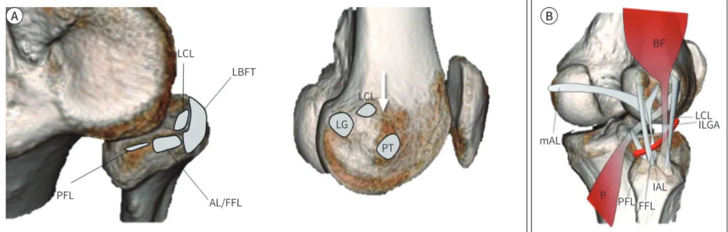
Fig. 1. Illustration demonstrating the normal anatomy of the posterolateral corner.
A. Origins and insertion of posterolateral corner components. The LCL attaches centrally on the fibular head and is surrounded by the LBFT footprint. The AL and FFL attach to the fibular styloid process posteriorly and the PFL attaches medial to the attachment of the AL and FFL (left image). On the lateral surface of the lateral femoral condyle, the LCL originates posterior to the lateral femoral epicondyle (arrow) and anterior to the lateral head of gastrocnemius tendon (LG). Whereas the PT originates inferior and slightly anterior to the lateral epicondyle (right image).
B. Courses of posterolateral corner components. The ‘P’ begins at the lateral surface of the lateral femoral condyle and passes deep to the LCL and the BF. Subsequently, the popliteus tendon passes under the mAL and lAL, and the FFL. The PFL is attached to the myotendinous junc- tion of popliteus tendon and anchors it onto the tip of the fibular styloid process. The ILGA passes between the AL and the FFL and is a land- mark used to distinguish between them.
AL = arcuate ligament, BF = biceps femoris tendon, FFL = fabellofibular ligament, lAL = lateral limbs of the arcuate ligaments, ILGA = inferior lat- eral genicular artery, LBFT = long head of biceps femoris tendon, LCL = lateral collateral ligament, LG = lateral head of gastrocnemius tendon, mAL = medial, P = popliteus tendon, PFL = popliteofibular ligament, PT = popliteus tendon
LCL
LCL
LG PT LBFT
AL/FFL PFL
LCLILGA mAL
P PFL FFLIAL
A B
BF BF
의 바로 바깥쪽에 부착한다(Fig. 1) (12). Arcuate ligament는 표준 시상영상 및 경사시상영상에서 얇은 저신호 띠로 나타나며, 약 10~46% 에서 확인되는 것으로 알려져 있다(Fig. 4) (5).
FFL는 fabella의 외측면에서, 그리고 fabella가 없는 경우에는 대퇴골의 과상 융기(supracondy- lar process)의 뒤쪽 면에서 부착하여 수직으로 아래로 내려와 비골 경상돌기 끝에 부착한다(7, 16).
MRI 영상에서는 약 33~48% 정도에서 확인된다(5). FFL은 시상 및 관상영상에서 arcuate ligament 와 아래 무릎혈관(inferior lateral genicular vessel)의 뒤쪽에서 보이게 되며, 축상영상에서는 외 측 비복건(lateral gastrocnemius tendon)의 앞쪽에서 보이게 된다(Fig. 4) (1).
Posterolateral Corner Injury
PLC의 손상은 단독 손상으로서 나타나기보다는 대부분 십자인대의 손상, 반월연골 열상, 또는
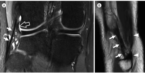
Fig. 3. Popliteofibular ligament and popliteomeniscal fascicle.
A, B. Coronal fat-suppressed intermediate-weighted and sagittal T2-weighted images show the popliteofibular ligament (arrows) which at- taches to the myotendinous junction of popliteus tendon (arrowheads).
C. Sagittal fat-suppressed intermediate-weighted image shows the anteroinferior (arrow) and the posterosuperior (arrowhead) popliteo- meniscal fascicles which connect the posterior horn of the lateral meniscus, the popliteus tendon, and the joint capsule.
A B C
Fig. 2. Lateral collateral ligament.
A. Coronal fat-suppressed intermediate-weighted image shows the entire course of the lateral collateral lig- ament (arrows) starting from the lateral femoral condyle to the fibular head. The intraarticular portion of the popliteus tendon (open arrow) located inner to lateral collateral ligament is also seen.
B. Sagittal T2-weighted image of the lateral aspect of fibular head shows the lateral collateral ligament (ar- rows) and the biceps femoris tendon (arrowheads) which insert on the fibular head.
A B
BF
내측측부인대의 손상과 동반되어 나타난다(5). 간과된 PLC 손상은 십자인대의 재건 이후에 지속되 는 슬관절의 만성 불안정성이나 만성 통증의 원인이 되고, 궁극적으로는 골관절염을 일으키는 등 나쁜 예후와 연관이 있다(17). LaPrade 등(18)은, 슬관절의 굴곡상태에서 내반력과 내회전력이 가 해졌을 때 재건된 전방십자인대 이식편에 가해지는 부하가, PLC를 제거한 슬관절에서 의미 있게 증가하므로 전방십자인대 재건시에 PLC의 재건이 동시에 이루어져야 한다는 것을 강조하였다. 최 근 연구에 의하면 PLC 재건이 필요한 후외측 불안정성을 예측하는데 있어 가장 중요한 예측 변수 는 PLC의 구성요소 중 외측측부인대의 완전 열상이며, 각각의 PLC 구조물들 하나하나를 평가하는 것이 환자의 치료 방향 설정에 크게 영향을 미치지는 않는다고 하였다(15).
Anterolateral Ligament Complex of the Knee
Dr. Segond (19)가 외측 경골의 견열골절(avulsion fracture)의 원인이 되는 섬유띠를 기술하였 고 슬관절의 바깥쪽에서 앞쪽으로 비스듬한 경로로 주행하는 인대와 같은 구조가 있다는 것이 알 려져 왔다(19). 이 구조물은 anterior band of LCL, lateral capsular ligament, anterior oblique band 등의 다양한 명칭으로 불려오다, 2007년 Vieira 등(20)에 의해 anterolateral ligament (이하 ALL)라는 명칭이 사용되기 시작하였다(20, 21). ALL의 기능은 최근에 주목받기 시작했는데, 슬관 절의 내회전을 제한하는 역할을 하는 것으로 알려져 있으며, PLC와 마찬가지로 전방십자인대 손 상 시 동반 손상의 빈도가 높아 수술적 재건에 대한 관심이 높아지고 있다(22).
그러나 가장 최근 연구들에 의하면, ALL이라는 독립된 구조물은 존재하지 않으며, 이를 슬관절 의 전외측 관절막과 연결성을 가지고 있는 iliotibial band (이하 ITB)의 성분으로 보는데, 이를 ITB 의 capsulo-osseous layer라 부른다(23). ALL은 외측 대퇴과(lateral femoral epicondyle)의 외측 측부인대 기시부 근처에서 부착하여, 아래쪽으로 비스듬하게 주행하여 ITB가 붙는 Gerdy’s tuber- cle 바로 뒤쪽의 경골 테두리에 부착한다(24). ALL의 원위 부착부 부근에서 ITB의 뒤쪽 경계와 연 결성이 있다(23). MRI 관상영상에서는 ITB가 마지막으로 확인되는 단면의 바로 뒤쪽 단면에서, 아
Fig. 4. Arcuate and fabellofibular ligament.A, B. Sagittal T2-weighted and axial fat suppressed intermediate weighted images show the lateral limb of arcuate ligament (arrows) and fa- bellofibular ligament (arrowheads). The inferior lateral genicular vessels (open arrows) pass between the arcuate ligament and the fabellofib- ular ligament (arrowheads).
C. Coronal fat-suppressed intermediate-weighted image shows the fabellofibular ligament (arrowheads) which originates from the fabella and inserts onto the fibular styloid process immediately lateral to the popliteofibular ligament.
A B C
래 무릎혈관(inferior lateral genicular vessel)의 바깥쪽에 위치하는, 지방조직에 의해 둘러싸인, 1~3 mm 두께의 얇은 선상의 띠 형태로 나타난다(Fig. 5). 축상영상에서는 슬관절의 외측면에서 ITB와 외측측부인대 사이에서 작은 타원형의 구조물로 보이게 된다(25) (Fig. 5). ALL이 경골에 붙 는 원위부착부는 거의 대부분 MRI 영상에서 비교적 일관되게 확인할 수 있지만, 근위부착부는 매 우 근접하여 위치하는 외측측부인대나 ITB, 관절막 등과 구별하기가 쉽지 않다(23).
최근 연구에 따르면 ALL 손상은 전방십자인대 파열의 79% 정도에서 동반되며, ALL 손상은 거 의 대부분 전방십자인대 파열에 동반되어 발생하는 것으로 알려져 있다(26). 하지만 전방십자인대 가 없는 슬관절에서 ALL의 역할에 대한 논쟁이 지속되고 있으며, ALL의 재건은 전방십자인대 재 건술 시 항상 권장되는 것은 아니다(24). 그러나 pivot-shift 기전으로 전방십자인대가 끊어진 슬관 절에서는 ALL 재건이 수술 후 나타날 수 있는 회전 불안정성(rotatory instability)을 감소시키는 것으로 알려져 있다(27).
ALL보다 근위부에서는 ITB를 대퇴골과 연결해주는 두 개의 섬유성 띠가 있다. 그중 더 원위부 대퇴골에 부착하는 섬유띠는 Kaplan (28)이 처음으로 외측 대퇴과 (lateral femoral condyle)의 septal insertion으로 기술하였기 때문에, Kaplan fiber라고 불린다. 이는 ITB에서 기시하여 원위 부로 비스듬하게 주행하여 외측 대퇴과에 부착하게 되므로, epicondylar band라고도 한다(29).
Epicondylar band의 경우 슬관절의 외측함요(lateral recess)에 굽어져 있는 띠의 형태로 나타나 며, 슬관절에 삼출액이 있는 경우 더욱 쉽게 확인이 가능하다(Fig. 6). ITB의 근위부 대퇴골 부착 섬 유띠는 역시 Kaplan에 의해 intermuscular septum inserting onto the lateral edge of the linea aspera로 기술되었고, Kaplan fiber와 구별하기 위해 proximal Kaplan fiber, 또는 proximal band of ITB로 부른다(23). 이 구조물은 위 무릎혈관(superior lateral geniculate vessel)의 위쪽으로 수 평으로 주행하여 외측 광근(vastus lateralis muscle)의 뒤쪽을 지나 대퇴골의 linea aspera에 부착 한다(Fig. 6) (29). 이 proximal band of ITB는 epicondylar band에 비하여 아래위로 긴 형태이다.
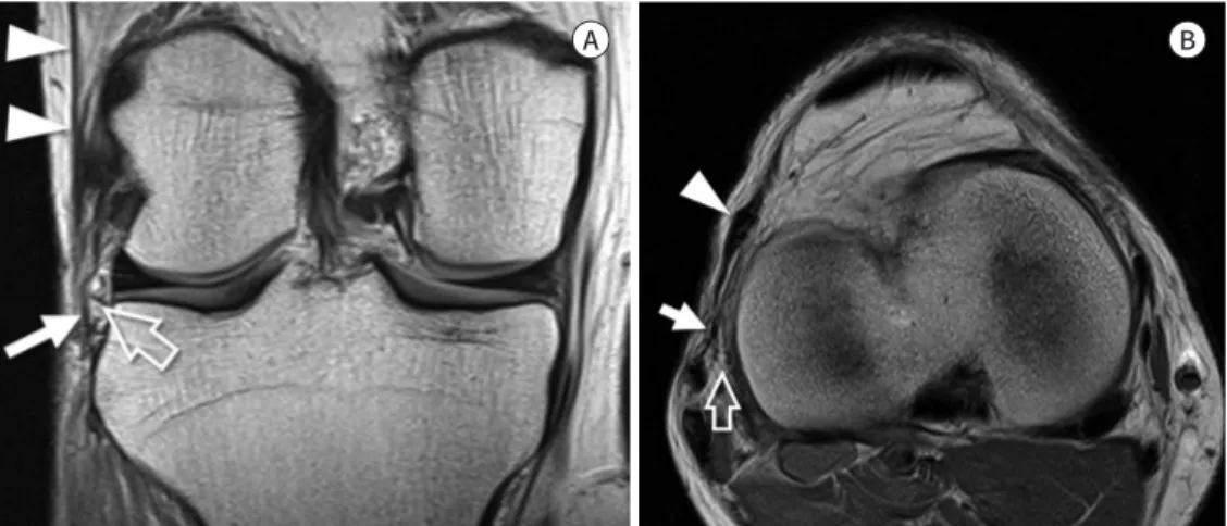
Fig. 5. Anterolateral ligament.
A, B. Coronal and axial proton density weighted images demonstrate the capsulo-osseous layer of iliotibial band, also known as the anterolateral ligament (arrows), which courses lateral to the inferior lateral genicu- lar vessel (open arrows) and finally inserts on the anterolateral tibial rim. The iliotibial band (arrowheads) courses anterior to the caspulo-osseous layer at the level of the joint and has a more anterior insertion on Gerdy’s tubercle.
A B
Rotator Cable of Shoulder
회전근개는 각각의 회전근개를 구성하는 건들과 관절막, 그리고 주변의 인대 등이 서로 만나면 서 복잡한 미세구조를 가지는 회전근개-관절막 복합체(cuff-capsule complex)를 이루고 있으며, 이의 구조와 기능에 대한 많은 연구가 이루어지고 있다.
Clark과 Harryman (30)은 이러한 회전근개-관절막 복합체를 조직학적으로 5층으로 구분하였 고 이는 이후 회전근개의 미세구조 연구에서 기본이 되는 내용이다. 가장 표층인 layer 1은 coraco- humeral ligament로 보았으며, layer 2는 내측에서 외측으로 주행하는, 평행하게 배열하고 있는 closely packed tendon bundle로 구성되어 있는 층이고, layer 3은 layer 2와 비슷한 조직이지만 좀 더 작은 직경의, 다소 비균질한 배열을 보이는 tendon bundle로 구성되어 있는 층이며, layer 4 는 coracohumeal ligament에서 나온 일부 섬유성분 및 layer 2의 bundle과 수직의 배열을 보이 는 bundle로 구성된 층이며, 마지막으로 가장 깊은 층인 layer 5는 관절막으로 이루어져 있다고 하 였다(Fig. 7).
Rotator cable은 극상근(supraspinatus)과 극하근(infraspinatus)의 밑면에서 앞뒤 방향으로 주 행하는, 섬유화 다발이다. 관절경 상에서는 반원형으로 보이는 회전근개 건의 무혈성 부위(avascu- lar zone)를 감싸고 있는 띠의 형태로 보인다(Fig. 8). 이 rotator cable이 감싸고 있는 반원형태의 무혈성 공간은 이와 구분하여 rotator crescent라고 부른다. Clark의 5 layer 중 layer 4가 바로 ro- tator cable에 해당하며, 이를 transverse band라고 하였다(30).
Burkhart 등(31)은 최초로 이 구조물을 rotator cable이라고 명명하였는데, 극상근과 극하근이 받는 장력을 rotator cable의 앞쪽 및 뒤쪽의 골 부착부로 전달함으로써, 취약한 회전근개의 무혈
Fig. 6. Anterolateral ligament complex.A. Coronal proton density weighted image shows the epicondylar band (arrows) anchoring the iliotibial band (arrowheads) to the femur.
B. Sagittal T2-weighted image demonstrates the proximal Kaplan fiber (arrows) of the iliotibial band attached to the linear aspera of the fem- oral shaft.
C. Illustration depicting the anterolateral ligament complex. Sagittal diagram shows the ITB, the EB, the PB, the SGA, the IGA, the JC, the LCL, and the ALL. The epicondylar band and the proximal band of the ITB run from the ITB and insert on the lateral femoral condyle and the linear aspera, respectively. The ALL originates near the origin of the LCL. It passes above the inferior lateral genicular artery, connects to the joint capsule, and inserts on the tibia.
ALL = anterolateral ligament, EB = epicondylar band, IGA = inferior lateral genicular artery, ITB = iliotibial band, JC = joint capsule, LCL = lateral collateral ligament, PB = proximal band of ITB, SGA = superior lateral genicular artery
A B C
ITB
PB EB SGA
IGA
LCL JC
ALL
성 부위에 가해지는 힘을 차단하는 stress-shielding의 역할을 한다고 추정하였다. 하지만 당시에 rotator cable의 두께를 극상건과 극하건을 포함하여 설명하였으나 현재는 앞서 말한 것과 같이 별
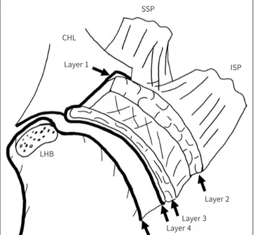
Fig. 7. Schematic diagram of a cross section through the SSP and theISP tendons, parallel to the surface of the glenoid.
Layer 1 is the most superficial, composed of fibers of the CHL extend- ing from the coracoid process to the greater tuberosity and overlies the cuff tendons. Layer 2 is composed of packed parallel tendon fibers ex- tending from the muscle belly of SSP and ISP to the humerus. Layer 3 has a tendinous structure with smaller fascicles compared to layer 2.
The fibers of SSP in layer 3 are intermingled with fibers from the adja- cent subscapularis and the ISP. Layer 4 is composed of loose connec- tive tissue having thick bands of collagen. Layer 5 is the deepest of all and forms the true joint capsule of the shoulder.
CHL = coracohumeral ligament, ISP = infraspinatus, LHB = long head of biceps tendon, SSP = supraspinatus
SSP CHL
LHB Layer 1
Layer 2 Layer 3 Layer 4 Layer 5
ISP
Fig. 8. Angled arthroscopic view of the humeral footprint of the supraspi- natus shows the RC (arrows) and the Cr. Long head of the ‘B’ slides through the bicipital groove behind humeral
‘H.’
B = biceps tendon, Cr = crescent, H = head, RC = rotator cable
RC
Cr
H B
망가진 경우, 그렇지 않은 경우보다 빨리 수술하는 것이 유리한 것으로 알려져 있다(33). 또한 Bur- khart (32)는 rotator cable과 rotator crescent의 상대적인 두께에 따라서, cable-dominant와 crescent-dominant인 개체로 나누었는데, cable-dominant는 상대적으로 노년층에 많고, cres- cent- dominant는 상대적으로 젊은 층에 많다고 설명하였다. 그러나 최근 초음파나 MRI를 이용 한 연구들에 의하면, crescent가 두꺼울수록 cable도 오히려 두꺼운 경향을 보이며, cable과 cres- cent의 상대적인 두께는 나이와는 크게 관련성이 없는 것으로 밝혀져, cable-dominant와 cres- cent-dominant에 대한 가설은 설득력을 잃고 있다(34, 35).
Rotator cable은 앞쪽에서는 coracohumeral ligament에서 유래한 섬유다발의 연속으로, 앞쪽 에서는 극상건의 앞쪽 경계에서 greater tuberosity에 부착하며, 뒤쪽에서는 극하건이나 소원건과 합쳐지면서 greater tuberosity에 부착한다.
MRI 영상에서는 극상건과 극하건의 밑면에 두드러져 보이는 저신호강도 띠의 형태로 나타나 며, 극상건의 섬유다발과 수직으로 주행하는 모양도 확인이 가능하다. MRI에서는 관상 및 시상면 에서 잘 보인다(Fig. 10). 앞에서는 극상건의 앞쪽 경계 부위와 합쳐지는 것을 확인할 수 있지만, 뒤 쪽의 건과의 부착부를 확인하기는 어렵다(36). Rotator cable이 다소 두꺼운 경우에 열상으로 인 해 수축된 회전근개의 건으로 오인하지 않도록 주의해야 한다.
한 사체 연구에 의하면 rotator cable의 너비는 정상 환자에서 mid portion의 경우에 8.95 ± 1.54 mm, 길이는 56.42 ± 10.13 mm, 두께는 1.56 ± 0.70 mm로 확인되었다(37).
Superior Capsule of Shoulder
견관절은 우리 몸에서 가장 가동성이 큰 관절로, 이로 인해 안정성을 유지하는 것이 중요하다.
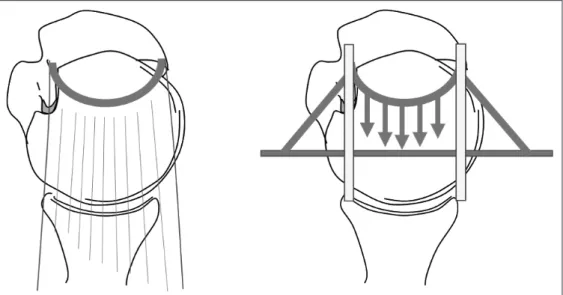
Fig. 9. “Suspension bridge model”.
Osseous attachment of the rotator cable is analogous to the pillars of a suspension bridge, and the rotator cable is analogous to the cable connecting the pillars. The tension generated by the rotator cuff tendon me- dial to the cable is transferred to the osseous attachment, thereby preserving the function of the tendon as well as limiting the progression of a tear (Reference 31).
관절을 가장 안쪽에서 감싸고 있는 관절순-인대 복합체(labroligamentous complex)는 정적인 안 정성을 유지하는데 있어 가장 주된 구조이다. 그동안 대부분의 견관절 불안정성 연구에서는 an- teroinferior 및 posterior capsuloligamentous structure에 대한 중요성이 강조되어 왔지만, 최 근에는 견관절이 생체역학적으로 정상적인 기능을 유지하는데 있어서 superior capsule의 중요성 이 강조되고 있다. Superior capsule은 Clark의 5번째 layer에 해당하며, 회전근개의 건에 밀착되 어 있어 회전근개와 해부학적, 생체역학적으로 밀접하게 연관되어 있다.
최근에 superior capsule이 견관절의 상방 이동을 막아주는 중요한 구조물이라는 것이 밝혀졌 으며, rotator cable 역시 과도한 힘이 가해졌을 때 superior capsule을 보호하는 stress-shielding 의 역할을 하는 것으로 알려져, 기능적으로 superior capsule의 일부로 받아들여지고 있다(38). 실 제로 superior capsule이 정상적으로 유지되고 있는 활액낭측 부분 파열(bursal-sided partial- thickness tear)이 관절측 부분파열(articular-sided partial-thickness tear)에서보다 기능적인 손 실이 덜하다는 점이 이를 뒷받침한다. 또한 완전 수복이 어려운 커다란 회전근개 파열이 있는 환자 에서 superior capsule을 재건하였을때, 결과가 더 좋다는 연구들이 계속 발표되고 있다(39, 40).
하지만 이러한 술식이 장기적으로 도움이 되는지에 대한 근거가 아직은 부족하다.
Superior capsule은 극상건의 밑면에 얇은 저신호강도의 구조물로 나타나며 극상건의 greater tuberosity 부착부의 안쪽에서부터 상부 관절순까지 연결되어 있다(41). 외측의 건 부위에서 더 견
Fig. 10. Rotator cable.A. Oblique coronal T2-weighted image demonstrates the prominent rotator cable (arrows) on the articular side of the supraspinatus tendon, also referred to as the “cable-dominant rotator cuff.”
B. Oblique coronal T2-weighted image demonstrates the superior capsule (arrows) on the articular side of the supraspinatus tendon devoid of a cable-like structure.
A B
경계 부위와 극하건의 뒤쪽 경계 부위에서 가장 두꺼웠는데, 이 부위에서 rotator cable과 만나 greater tuberosity에 부착하기 때문으로 생각된다.
Supraspintus Tendon Slip
MRI의 축상영상에서 이두근 고랑(bicipital groove)을 따라 내려가는 이두근 장두(long head of biceps tendon)의 앞쪽을 따라서 수직으로 주행하는 건과 같은 구조물이 보이는 경우가 있다.
Gheno 등(44)은 이 구조물을 부 이두근건(accessory biceps tendon)으로 기술하였다. 그러나 이 전의 많은 해부학 연구에서 밝혀진 이두근 고랑을 따라서 주행하는 구조물인, 극상건의 accessory slip 또는 aponeurotic expansion도 이와 비슷한 주행을 가진다(30, 45).
Moser 등(46)은 150개의 견관절 MRI 영상을 분석하였을 때 약 반 정도에서 이두근 고랑 주변에 서 이러한 구조물을 확인할 수 있었다. 이 구조물은 MRI에서 저신호강도를 보였으며, 얇고 납작한 형태에서부터 좀 더 크고 타원형의 형태까지 다양하게 나타났다. 이 연구에서는 약 35%가 납작한 형태를 보였으며 21%에서는 타원형의 건과 비슷한 구조물의 형태로 보인다고 하였다(Fig. 12) (46).
극상건의 가장 앞쪽에 위치한 표층의 섬유질에서 기시하여, 대흉근(pectoralis major) 건의 위쪽 경계 부위로 부착하는 것으로 보아 부 이두근건(accessory biceps tendon)으로 보는 것보다는 극 상건의 aponeurotic expansion 혹은 accessory slip으로 보는 것이 더 적절하다. 조직학적으로 건 을 구성하는 collagen fascicle들로 구성되어 있었으며 근조직은 확인되지 않았다(44, 46). MRI 영 상에서에서 이두근 장두의 분열 파열(split tear)로 오인할 수 있어 주의가 필요하다.
Distal Tibiofibular Syndesmosis of Ankle
원위부 경비골 인대결합(distal tibiofibular syndesmosis)은 발목관절의 안정성에 있어서 중요
Fig. 11. Superior capsule of shoulder.A. Oblique coronal T2-weighted MR arthrography shows the superior capsule (arrows) and its footprint (ar- rowhead) on the greater tuberosity.
B. Oblique sagittal T2-weighted MR arthrography shows the superior capsule (arrows) in continuum with the coracohumeral ligament (arrowhead).
A B
한 역할을 한다. 원위부 인대결합의 가장 아래쪽에는 경골과 비골이 직접 접하는 관절이 존재하며 사이에는 0.5 mm 정도의 얇은 유리연골이 덮고 있다. 주변으로 anteroinferior tibiofibular liga- ment (이하 AITFL), posteroinferior tibiofibular ligament (이하 PITFL), 그리고 interosseous tibiofibular ligament (이하 IOL)가 경골과 비골을 단단하게 결합시켜 관절을 안정화 시킨다. 이러 한 인대의 손상이 있는 경우에 경골-거골 관절(tibiotalar joint)의 접촉면적을 감소시켜 발목관절 불안정성을 초래한다(47-49).
생체역학 연구에 따르면 원위부 경비골에서 인대결합을 이루는 각각의 인대들이 관절 안정성에 기여하는 정도는 AITFL이 35%, IOL가 22%, 그리고 PITFL이 42% 정도라고 한다(50).
Anteroinferior Tibiofibular Ligament
AITFL은 거골과 비골의 외회전을 막아주는 역할을 한다(51). AITFL은 사다리꼴 형태를 가지고 있으며, 원위부 경골의 전방결절(anterior tubercle, chaput tubercle)과 원위부 비골의 전방결절 에 부착한다. 이 사이에서 거골의 전외측 모서리를 가로지르며, 외측 방향으로 비스듬하게 주행한 다. AITFL은 4개의 인대결합을 이루는 인대중에 가장 약한 것으로 알려져 있다(52). AITFL은 3~4 개의 다발로 구성되어 있으며 사이에 지방조직이 끼어있다(49). 중간 부분이 가장 강하며, 이 중간 부분은 3~4개의 더 작은 인대로 나누어지기도 한다(49). 각각의 다발은 관상영상에서 볼 때 2 mm
Fig. 12. Supraspinatus tendon slip.A. Axial T2-weighted MR arthrography shows the supraspinatus tendon slip (arrow) in the bicipital groove lateral to the long head of the biceps tendon (arrowhead).
B. Oblique sagittal T2-weighted MR arthrography shows the course of the supraspinatus tendon slip (ar- rows) which originates from anterior margin of the supraspinatus and attaches to the humerus adjacent to the pectoralis major tendon.
A B
에서 확인되는 것으로 알려져 있다(54, 55). Bassett’s ligament는 해부학적으로 경골의 AITFL의 부착부 가장 아래쪽에서 전외측으로 비스듬하게 주행하여 비골의 anterior talofibular ligament 근위부에 부착하게 된다. 다른 AITFL보다는 약간 더 수평으로 주행한다(56). AITFL과는 섬유지방 조직에 의해서 분명하게 구분되며, 경우에 따라 2~3개 혹은 그 이상의 띠로 구분되어 보인다.
Bassett’s ligament는 MRI 축상, 관상, 그리고 시상 단면에서 모두 잘 확인할 수 있고, 특히 비스 듬한 관상면으로 재구성하였을 때 인대 주행 전체를 한 영상에서 확인할 수 있다(Fig. 13B) (55).
Bassett’s ligament는 발목에서 전외측 충돌 증후군(anterolateral impingement)의 원인이 될 수 있다고 알려져 왔는데, anterior talofibular ligament의 부상으로 불안정성이 초래되고, 이로 인 해 발등의 굴곡시에 거골이 앞으로 나오게 되면, Bassett’s ligament가 거골의 전외측 반구와 접촉 하게 되어 증상을 일으키는 것으로 추정하고 있다. MRI 상에서는 발목관절의 전외측 고랑(antero- lateral gutter)에 활액막염 및 섬유화 반흔 등의 소견이 동반된다. 보존적 치료를 시행할 수 있는 데, 반응이 없는 경우 이를 절제하여 좋은 결과를 보였다고 보고되어 있다(57). Bassett’s ligament 를 수술적으로 제거한 군과 무증상의 대조군을 비교한 연구에 따르면, 축상영상에서 인대의 두께 는 수술적 제거군에서 평균 2.37 mm, 대조군에서 평균 1.87 mm로 의미 있는 차이를 보였다(55).
Posteroinferior Tibiofibular Ligament Complex
PITFL은 원위부 경비골 인대결합에서 가장 강한 인대로 비골이 뒤쪽으로 전위되는 것을 막는 역할을 한다. PITFL은 사각형 형태를 가지고 있으며, AITFL과 마찬가지로 여러 개의 다발로 구성 되어 있다. 경골의 후방 복사(posterior tibial malleolus)의 Volkmann’s tubercle과 비골의 후방 결절(posterior tubercle)에 부착한다.
PITFL은 superficial PITFL과 deep PITFL로 나눌 수 있으며 이 중 superficial PITFL은 경골의
Fig. 13. Anteroinferior tibiofibular ligament.A. Consecutive axial T2-weighted images show obliquely oriented anteroinferior tibiofibular ligament (arrows) with origin at the tibia (left) and a fibular insertion (right).
B. Oblique coronal reformatted three-dimensional fast spin-echo T2-weighted image shows the entire course of the anteroinferior fibular liga- ment (arrows) which is composed of multiple bundles. The inferior most bundle is the Basset’s ligament (arrowheads).
A B
후방에서 비교적 넓은 부위에서 부착하여, 비스듬하게 아래 바깥쪽 방향으로 주행하여 비골의 후 방결절에 부착한다(58). MRI의 축상영상에서 보면 superficial PITFL의 경골 부착 부위는 비골근 이 주행하는 바로 내측에서 확인할 수 있다. 이 인대는 AITFL과 함께 비골을 경골의 비골 고랑(fib- ular groove)에 고정시키는 역할을 하게 된다(59).
Deep PITFL은 superficial PITFL에 비해 경골의 내측 원위부에 부착하며, 더 심층에 위치한다 (Fig. 14). Superficial PITFL보다 다소 수평으로 주행하여 비골의 후방결절에 superficial PITFL 과 함께 부착한다(53). Deep PITFL을 독립적으로 inferior transverse ligament라고도 부르기도
sPITFL dPITFL
IML PTFL
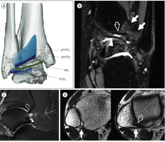
Fig. 14. Posteroinferior tibiofibular ligament complex.
A. PITFL complex. The wide sPITFL originates from the posterior tubercle of the tibia and inserts on the pos- terior tubercle of the fibula. The dPITFL originates immediately inferior to the sPITFL and inserts on the posterior tubercle, deeper to the sPTIFL. The IML connects the inner surface of the medial malleolus and the lateral malleolus where the PTFL originates.
B. Coronal fat-suppressed three-dimensional fast-spin echo sequence demonstrates the superficial PITFL (arrows), the dPITFL (open arrow), and the IML (arrowhead).
C. Sagittal fat-suppressed intermediate-weighted image demonstrates the dPITFL (open arrow) which ap- pears like a “labrum” of the tibial rim, and the IML (arrowhead) which restricts the expansion of the posteri- or recess of the ankle.
D. Axial T2-weighted images demonstrate the sPITFL (arrows) that originates from the posterior tubercle of tibia and inserts into posterior tubercle of fibula. The dPITFL (arrowhead) inserts deeper than the sPITFL into the posterior tubercle of the fibula.
dPITFL = deep PITFL, IML = intermalleolar ligament, PITFL = posterior inferior tibiofibular ligament, PTFL = posterior talofibular ligament, sPITFL = superficial PITFL
A B
C D
한다. 많은 연구자들은 deep PITFL은 경골의 관절면을 깊게 만들어주는, 마치 견관절의 관절순과 비슷한 역할을 한다고 생각하고 있다(60).
PITFL은 두껍고 강한 인대이고 경골이 매우 넓게 붙기 때문에, 과도한 외력이 가해졌을 때 인대 자체가 끊어지기보다는 경골 후방 복사(posterior malleolus)의 maisonneuve fracture와 같은 견 열골절이 더 흔하게 발생하는 것으로 알려져 있다(49).
Intermalleolar ligament는 tibial slip이라고도 부르며, deep PITFL 보다 아래쪽에 위치하여, 외측 복사(lateral malleolus)의 아래쪽, posterior talofibular ligament가 붙는 위치에서 부착하 여 내측복사(medial malleolus)에 다양한 형태로 부착하는, PITFL과는 분리된 인대로 발목관절 의 후방 공간을 지난다(Fig. 14). MRI에서 얇은 섬유화 띠 혹은 두꺼운 끈의 형태 등 다양하게 나타 나며, 일부에서는 두세 가닥으로 분리되어 보이는 경우도 있다(61). 약 80%에서 관찰되는 것으로 보고되고 있다.
Interosseous Membrane and Interosseous Ligament
Interosseous membrane은 경골과 비골의 사이를 연결하는 두꺼운 근막과 비슷한 구조물로 경 골 외측 모서리 골막에서 기시하여 비골에 부착한다. Interosseous membrane의 가장 아래쪽 부 분은 두꺼워져서 피라미드 형태의 인대와 같은 구조를 형성하는데 이를 interosseous ligament라 부른다(49). Interosseous ligament는 경골에서 비골로 비스듬하게 주행하는데, 경골의 근위부에 서는 좀 더 앞뒤로 넓게 앞쪽에 부착하고, 원위부에서는 얇게 뒤쪽에 부착한다(61). Interosseous ligament는 경골의 관절면에서 약 1~2 cm 상방에 위치한다.
Interosseous ligament는 기본적으로 비골의 외측 전위를 막아주는 역할을 하지만, 이외에도 발등의 굴곡시에 발생하는 생리적인 경비골 간의 분리를 가능하게 하고, 발이 땅에 닿을 때 발생 하는 힘을 수용하기 위하여 일종의 스프링처럼 작용하는 것으로 알려져 있다(Fig. 15) (49).
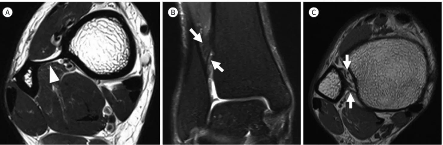
Fig. 15. Interosseous membrane and interosseous ligament.
A. Axial T2-weighted image shows the interosseous membrane (arrowhead) that connects the lateral margin of the tibia and the medial mar- gin of the fibula.
B, C. Coronal fat-suppressed T2-weighted and axial T2-weighted images show obliquely oriented interosseous ligament (arrows) composed of proximal and distal bands.
A B C
결론
본 종설에서는 관절의 안정성과 관련된 해부학으로, 최근 많은 연구가 이루어지고 있는 슬관절 의 후외측 및 전외측 복합체, 견관절의 회전근개 케이블 및 상관절막, 마지막으로 발목관절의 원 위부 경비골 인대결합(distal tibiofibular syndesmosis)에 대해 알아보았다. 각각의 기시부와 부 착부, 인접 구조물과의 위치관계를 통해 MRI에서 대부분 확인이 가능하였다. 기술된 해부학적 구 조물들은 수술적 복원이나 재건의 필요성에 대해 활발하게 논의되고 있는 것들로, 이들의 MRI 영 상소견에 대해 친숙해짐으로써 해부학적인 이해의 폭을 넓히고 임상의들과의 원활한 소통에도 도 움을 줄 수 있을 것이다.
Author Contributions
Conceptualization, all authors; project administration, all authors; resources, J.J.; supervision, J.J.;
visualization, P.H.; and writing—original draft, all authors.
Conflicts of Interest
The authors have no potential conflicts of interest to disclose.
REFERENCES
1. Rosas HG. Unraveling the posterolateral corner of the knee. Radiographics 2016;36:1776-1791
2. DeLee JC, Riley MB, Rockwood CA Jr. Acute posterolateral rotatory instability of the knee. Am J Sports Med 1983;11:199-207
3. Hughston JC, Jacobson KE. Chronic posterolateral rotatory instability of the knee. J Bone Joint Surg Am 1985;67:351-359
4. Seebacher JR, Inglis AE, Marshall JL, Warren RF. The structure of the posterolateral aspect of the knee. J Bone Joint Surg Am 1982;64:536-541
5. Bolog N, Hodler J. MR imaging of the posterolateral corner of the knee. Skeletal Radiol 2007;36:715-728 6. Vinson EN, Major NM, Helms CA. The posterolateral corner of the knee. AJR Am J Roentgenol 2008;190:449-458 7. Munshi M, Pretterklieber ML, Kwak S, Antonio GE, Trudell DJ, Resnick D. MR imaging, MR arthrography, and
specimen correlation of the posterolateral corner of the knee: an anatomic study. AJR Am J Roentgenol 2003;180:1095-1101
8. Brinkman JM, Schwering PJ, Blankevoort L, Kooloos JG, Luites J, Wymenga AB. The insertion geometry of the posterolateral corner of the knee. J Bone Joint Surg Br 2005;87:1364-1368
9. De Maeseneer M, Shahabpour M, Vanderdood K, De Ridder F, Van Roy F, Osteaux M. Posterolateral support- ing structures of the knee: findings on anatomic dissection, anatomic slices and MR images. Eur Radiol 2001;11:2170-2177
10. Davies H, Unwin A, Aichroth P. The posterolateral corner of the knee. Anatomy, biomechanics and manage- ment of injuries. Injury 2004;35:68-75
11. Gollehon DL, Torzilli PA, Warren RF. The role of the posterolateral and cruciate ligaments in the stability of the human knee. A biomechanical study. J Bone Joint Surg Am 1987;69:233-242
12. Lee J, Papakonstantinou O, Brookenthal KR, Trudell D, Resnick DL. Arcuate sign of posterolateral knee injuries:
anatomic, radiographic, and MR imaging data related to patterns of injury. Skeletal Radiol 2003;32:619-627
16. Diamantopoulos A, Tokis A, Tzurbakis M, Patsopoulos I, Georgoulis A. The posterolateral corner of the knee:
evaluation under microsurgical dissection. Arthroscopy 2005;21:826-833
17. Covey DC. Injuries of the posterolateral corner of the knee. J Bone Joint Surg Am 2001;83:106-118
18. LaPrade RF, Resig S, Wentorf F, Lewis JL. The effects of grade III posterolateral knee complex injuries on an- terior cruciate ligament graft force. A biomechanical analysis. Am J Sports Med 1999;27:469-475
19. Segond P. Recherches cliniques et expérimentales sur les épanchements sanguins du genou par entorse.
Paris: Aux Bureaux du Progrès médical 1879:297-299
20. Vieira EL, Vieira EA, Da Silva RT, Berlfein PA, Abdalla RJ, Cohen M. An anatomic study of the iliotibial tract. Ar- throscopy 2007;23:269-274
21. Hughston JC, Andrews JR, Cross MJ, Moschi A. Classification of knee ligament instabilities. Part II. The lateral compartment. J Bone Joint Surg Am 1976;58:173-179
22. Van der Watt L, Khan M, Rothrauff BB, Ayeni OR, Musahl V, Getgood A, et al. The structure and function of the anterolateral ligament of the knee: a systematic review. Arthroscopy 2015;31:569-582.e3
23. Herbst E, Albers M, Burnham JM, Fu FH, Musahl V. The anterolateral complex of the knee. Orthop J Sports Med 2017;5:2325967117730805
24. Coquart B, Le Corroller T, Laurent PE, Ollivier M, Pradel V, Champsaur P, et al. Anterolateral ligament of the knee: myth or reality? Surg Radiol Anat 2016;38:955-962
25. Helito CP, Helito PV, Costa HP, Bordalo-Rodrigues M, Pecora JR, Camanho GL, et al. MRI evaluation of the anterolateral ligament of the knee: assessment in routine 1.5-T scans. Skeletal Radiol 2014;43:1421-1427 26. Claes S, Bartholomeeusen S, Bellemans J. High prevalence of anterolateral ligament abnormalities in mag-
netic resonance images of anterior cruciate ligament-injured knees. Acta Orthop Belg 2014;80:45-49 27. Levy BA, Sabbag OD. Editorial commentary: is anterolateral ligament reconstruction of the knee needed?
The debate rages on. Arthroscopy 2017;33:1584-1586
28. Kaplan EB. The iliotibial tract; clinical and morphological significance. J Bone Joint Surg Am 1958;40:817-832 29. Khanna M, Gupte C, Dodds A, Williams A, Walker M. Magnetic resonance imaging appearances of the capsu- lo-osseous layer of the iliotibial band and femoral attachments of the iliotibial band in the normal and piv- ot-shift ACL injured knee. Skeletal Radiol 2019;48:729-740
30. Clark JM, Harryman DT 2nd. Tendons, ligaments, and capsule of the rotator cuff. Gross and microscopic anatomy. J Bone Joint Surg Am 1992;74:713-725
31. Burkhart SS, Esch JC, Jolson RS. The rotator crescent and rotator cable: an anatomic description of the shoulder’s “suspension bridge.” Arthroscopy 1993;9:611-616
32. Burkhart SS. Fluoroscopic comparison of kinematic patterns in massive rotator cuff tears. A suspension bridge model. Clin Orthop Relat Res 1992;284:144-152
33. Mesiha MM, Derwin KA, Sibole SC, Erdemir A, McCarron JA. The biomechanical relevance of anterior rotator cuff cable tears in a cadaveric shoulder model. J Bone Joint Surg Am 2013;95:1817-1824
34. Morag Y, Jacobson JA, Lucas D, Miller B, Brigido MK, Jamadar DA. US appearance of the rotator cable with histologic correlation: preliminary results. Radiology 2006;241:485-491
35. Choo HJ, Lee SJ, Kim DW, Park YM, Kim JH. Assessment of the rotator cable in various rotator cuff condi- tions using indirect MR arthrography. Acta Radiol 2014;55:1104-1111
36. Gyftopoulos S, Bencardino J, Nevsky G, Hall G, Soofi Y, Desai P, et al. Rotator cable: MRI study of its appear- ance in the intact rotator cuff with anatomic and histologic correlation. AJR Am J Roentgenol 2013;200:
1101-1105
37. Podgórski MT, Olewnik L, Grzelak P, Polguj M, Topol M. Rotator cable in pathological shoulders: comparison with normal anatomy in a cadaveric study. Anat Sci Int 2019;94:53-57
38. Adams CR, DeMartino AM, Rego G, Denard PJ, Burkhart SS. The rotator cuff and the superior capsule: why we need both. Arthroscopy 2016;32:2628-2637
39. Mihata T, Lee TQ, Watanabe C, Fukunishi K, Ohue M, Tsujimura T, et al. Clinical results of arthroscopic superi- or capsule reconstruction for irreparable rotator cuff tears. Arthroscopy 2013;29:459-470
40. Adams CR, Denard PJ, Brady PC, Hartzler RU, Burkhart SS. The arthroscopic superior capsular reconstruc- tion. Am J Orthop (Belle Mead NJ) 2016;45:320-324
41. Clark J, Sidles JA, Matsen FA. The relationship of the glenohumeral joint capsule to the rotator cuff. Clin Or- thop Relat Res 1990;254:29-34
42. Yuri T, Kobayashi H, Takano Y, Yoshida S, Naito A, Fujii H, et al. Capsular attachment of the subregions of ro-
tator cuff muscles. Surg Radiol Anat 2019;41:1351-1359
43. Nimura A, Kato A, Yamaguchi K, Mochizuki T, Okawa A, Sugaya H, et al. The superior capsule of the shoulder joint complements the insertion of the rotator cuff. J Shoulder Elbow Surg 2012;21:867-872
44. Gheno R, Zoner CS, Buck FM, Nico MA, Haghighi P, Trudell DJ, et al. Accessory head of biceps brachii muscle:
anatomy, histology, and MRI in cadavers. AJR Am J Roentgenol 2010;194:W80-W83
45. Brodie CG. Note on the transverse-humeral, coraco-acromial, and coraco-humeral ligaments, &c. J Anat Physiol 1890;24:247-252
46. Moser TP, Cardinal É, Bureau NJ, Guillin R, Lanneville P, Grabs D. The aponeurotic expansion of the supra- spinatus tendon: anatomy and prevalence in a series of 150 shoulder MRIs. Skeletal Radiol 2015;44:223-231 47. Ramsey PL, Hamilton W. Changes in tibiotalar area of contact caused by lateral talar shift. J Bone Joint Surg
Am 1976;58:356-357
48. Harris J, Fallat L. Effects of isolated Weber B fibular fractures on the tibiotalar contact area. J Foot Ankle Surg 2004;43:3-9
49. Hermans JJ, Beumer A, De Jong TA, Kleinrensink GJ. Anatomy of the distal tibiofibular syndesmosis in adults: a pictorial essay with a multimodality approach. J Anat 2010;217:633-645
50. Ogilvie-Harris DJ, Reed SC, Hedman TP. Disruption of the ankle syndesmosis: biomechanical study of the ligamentous restraints. Arthroscopy 1994;10:558-560
51. Sarsam IM, Hughes SP. The role of the anterior tibio-fibular ligament in talar rotation: an anatomical study.
Injury 1988;19:62-64
52. Kelikian H, Kelikian AS. Disorders of the ankle. Philadelphia: WB Saunders Company 1985:4-8
53. Bartonícek J. Anatomy of the tibiofibular syndesmosis and its clinical relevance. Surg Radiol Anat 2003;25:
379-386
54. Bassett FH 3rd, Gates HS 3rd, Billys JB, Morris HB, Nikolaou PK. Talar impingement by the anteroinferior tib- iofibular ligament. A cause of chronic pain in the ankle after inversion sprain. J Bone Joint Surg Am 1990;72:
55-59
55. Subhas N, Vinson EN, Cothran RL, Santangelo JR, Nunley JA 2nd, Helms CA. MRI appearance of surgically proven abnormal accessory anterior-inferior tibiofibular ligament (Bassett’s ligament). Skeletal Radiol 2008;
37:27-33
56. Akseki D, Pinar H, Yaldiz K, Akseki N, Arman C. The anterior inferior tibiofibular ligament and talar impinge- ment: a cadaveric study. Knee Surg Sports Traumatol Arthrosc 2002;10:321-326
57. Akseki D, Pinar H, Bozkurt M, Yaldiz K, Araç S. The distal fascicle of the anterior inferior tibio-fibular ligament as a cause of anterolateral ankle impingement: results of arthroscopic resection. Acta Orthop Scand 1999;
70:478-482
58. Jayatilaka MLT, Philpott MDG, Fisher A, Fisher L, Molloy A, Mason L. Anatomy of the insertion of the posterior inferior tibiofibular ligament and the posterior malleolar fracture. Foot Ankle Int 2019;40:1319-1324 59. Norkus SA, Floyd RT. The anatomy and mechanisms of syndesmotic ankle sprains. J Athl Train 2001;36:68-73 60. Grath GB. Widening of the ankle mortise: a clinical and experimental study. Acta Chir Scand Suppl
1960;Suppl 263:1-88
61. Boonthathip M, Chen L, Trudell DJ, Resnick DL. Tibiofibular syndesmotic ligaments: MR arthrography in ca- davers with anatomic correlation. Radiology 2010;254:827-836
근골격 해부학의 최신 지견 및 자기공명영상 소견
박혜림 · 정준용*
MRI 영상은 관절 내 질환의 평가에 중요한 검사기법이며, 관절 MRI 영상의 해석을 위해선 견 고한 해부학적 지식이 바탕이 되어야 한다. 관절의 해부학 분야에서는, 새로운 구조물이 발견 되기도 하며, 과거에 보고되었으나 기능을 알지 못하던 구조물이 새롭게 주목을 받기도 한다.
본 종설에서는 최근 십여 년간 활발하게 연구되어온 견관절 회전근개 케이블(rotator cable) 및 상관절막(superior capsule), 슬관절의 후외측(posterolateral corner) 및 전외측 인대 복 합(anterolateral ligament complex), 발목관절의 원위부 경비골 인대결합(distal tibiofibu- lar syndesmosis) 등의 최근 연구 결과를 소개하고, 이를 MRI 영상을 통해 확인해 보았다.
가톨릭대학교 의과대학 서울성모병원 영상의학과