Powder Injection Molding of Translucent Alumina using Supercritical Fluid Debinding
Hyung Soo Kim, Jong Min Byun, Myung Jin Suka, and Young Do Kim*
Department of Materials Science and Engineering, Hanyang University, Seoul 133-791, Korea
aDepartment of Materials and Metallurgical Engineering, Kangwon National University, Samchok 245-711, Korea (Received October 7, 2014; Revised October 27, 2014; Accepted November 26, 2014)
···
Abstract The powder injection molding process having advantages in manufacturing three-dimensional precision parts essentially requires a debinding process before sintering to remove the binders used for preparing feedstock. In this study, powder injection molding of translucent alumina was performed, and carbon dioxide (CO2) is used as a super- critical fluid that makes it possible to remove a large amount of binder, which is paraffin wax. The relationship between the optical property of translucent alumina and the debinding condition (temperature and pressure) of supercritical CO2 was investigated. As temperature and pressure increased, extraction rate of the binder showed rising tendency and aver- age grain size after sintering process was relatively fine. On the other hand, optical transmittance was reduced. As a result, the debinding condition at 50oC and 20 MPa that represents the lowest extraction rate, 8.19× 10⁻³ m2/sec, cor- responds to the largest grain size of 14.7 µm and the highest optical transmittance of 45.2%.
Keywords: Powder injection molding (PIM), Translucent alumina, Carbon dioxide supercritical fluid, Debinding
···
1. Introduction
As there is a tendency that core precision parts, which are made of ceramics and metals, used in IT have increasingly been changed as thin and light and require various designs, these parts are determined as precise and complicate designs. Because complicate parts represent difficulties in fabricating it using an average molding method and need high processing cost, a powder injec- tion molding (PIM) technology that can implement mold- ing with low cost has been largely used[1]. As the PIM technology has a large advantage in performing low cost mass productions of metal and ceramic parts, which show difficulties in its processing, without applying sec- ondary processing processes, applications of this technol- ogy have largely been increased in these days[2-3].
However, PIM requires many hours for removing organic binders in a green body before applying a sintering pro- cess because PIM represents a very high rate of organic binders versus powder compared to that of powder metal- lurgy (PM). In addition, there is a significant environ-
mental issue of causing various hazardous substances, which are generated during the burning of organic mate- rials[4]. Therefore, the PIM technology needs a high cost pollution protection system including sintering equipments and molding expenses and has been limitedly applied to some special high price products even though it has a prominent advantage in fabricating practical molds. A debinding process in the PIM process requires longest hours technically compared to molding and sintering pro- cesses and becomes a most difficult process because it causes many defects in a green body during the dissolv- ing and removing of binders[5].
Ceramic injection modeling (CIM) consists of feed- stock, which is a mixture of powder and binder, fabrica- tion, injection, dewaxing, and sintering processes. Regarding the particle size of the alumina powder applied to develop transparent ceramic it represents a sub-micron scale and requires many hours for a dewaxing process that uses a conventional method based on heat or an organic sol- vent. Also, the process increases reprocessing expenses for preventing environmental pollutions caused by the
*Corresponding Author : Young Do Kim, TEL: +82-2-2220-0408, FAX: +82-2-2220-4231, E-mail: [email protected]
<PM리뷰>
use of toxic materials and solvents in its debinding pro- cess and that represents economic disadvantages[6-7].
In particular, a limitation of the process is the chal- lenge of removing binders between small alumina parti- cles that affect the production of high quality parts. In this study powder injection molding of translucent alu- mina was carried out with the debinding process using supercritical fluids[8-9]. A supercritical fluid is a type of fluid that exists above the critical point in temperature and pressure of the liquid-vapor equilibrium. Above the critical point, there is no physical distinction between the liquid and gaseous states. Debinding based on a super- critical-fluid technology does not produce pollutants and makes it possible to recycle the binders. The supercriti- cal fluid has high diffusivity that leads to a significant reduction in extraction time and is suitable for energy sav- ing processes[10]. In addition, it allows the production of high quality translucent alumina parts without physical damage to the debound part. This study shows the relation- ship between the extraction rate of the binder and the debinding condition of supercritical CO2 (temperature and pressure). The effect of the grain size on the optical prop- erty of translucent alumina was also examined.
A critical point represents the temperature and vapor pressure at a critical state in which two different state of liquid and gas cannot be identified for each other. A
supercritical fluid shows a state in which both the tem- perature and pressure are higher than a critical point.
As shown in Fig. 1, as the temperature presented in a pressure-temperature phase diagram increases and approaches to a level over a critical point, the phases of liquid and gas cannot be identified for each other and approach to a critical state in which the temperature and vapor pres- sure represent a critical point. A supercritical fluid that is presented at a level over its critical point shows a physi- cal characteristic that shows a middle state between liq- uid and gas[7, 11-12]. The supercritical fluid represents a unique characteristic that shows large changes in physi- cal characteristics including density according to a small change in pressure at around a critical point compared to that of the conventional solvent5]. As shown in Table 1, it shows viscosity and diffusion coefficients that approach to gas with excellent fluidity and represents density as similar to liquid. A physical characteristic in solvents is deter- mined by the interaction between molecules that can be presented by the type of molecules and the distance between molecules. Thus, as a liquid solvent shows an incompressible characteristic, the distance between mole- cules is not mostly changed and that makes a difficulty in expecting large changes in physical characteristics[14].
However, as the supercritical fluid can change a density level from a lean state, which is close to an ideal gas, to Fig. 1. Phase(pressure-temperature) diagram for CO2.
Table 1. Comparative physical properties of gas, supercritical fluid, liquid [13]
Property Phase
Gas Supercritical fluid Liquid
Density (g/cm3) (0.6-2.0) × 10−3 0.2-0.9 0.6-1.6
Dynamic Viscosity (cP) (1-3) × 10−3 (1.0-9.0) × 10−2 0.2-2.0
Diffusion Coefficient (cm2/sec) 0.1-0.4 (0.2-0.7) × 10−3 (0.2-2.0) × 10−5
a high density state, which is close to liquid, continu- ously, it can control not only both the parallel physical characteristics (solubility and Entrainer effect) and the transmission physical characteristics (viscosity, diffusion characteristic, and thermal conductivity) but also both the salvation and the molecule cluster state.
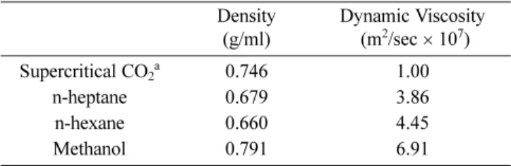
As shown in Table 2, although the supercritical CO2 and methanol show similar density levels, the dynamic viscosity of the supercritical CO2 is lower than the meth- anol about seven times. Because the solvation capability in a solvent is closely related to the density of the sol- vent, a supercritical fluid that has a similar density level to liquid represents a high solubility as similar to a liq- uid solvent. This characteristic allows an effective dew- axing process that shows fast penetration into fine pores between particles. In the dewaxing process using a super- critical fluid, it is possible to perform an effective dewax- ing process that dissolves included binders and is able to control the solubility and diffusivity according to included binders. That is, it makes possible to obtain more effec- tive dewaxing rates as a proper condition is maintained by calculating the solubility parameter and diffusivity of binders, which are well dissolved in a supercritical fluid,
in advance[1]. In the case of the dewaxing process using the supercritical CO2, it becomes a new technology that shows advantages in mass production, recycling of dew- axed binders, reducing processing time more than 10 times compared to that of heating dewaxing methods, reducing deformations in a green body and etc. even though it requires early expanding.
2. Experimental Procedure
2.1. Fabrication and injection molding of the feedstock The binder used in this study consists of two different components; a main binder and a sub-binder. Paraffin wax was used as the main binder and low-density poly- ethylene (LDPE: molecular weight of 50,000-100,000) and ethylvinylacetate (EVA) were used as the sub-bind- ers. Stearic acid (SA) was used as the additive. Feed- stock for injection molding was prepared by mixing the alumina (α-Al2O3)powder (AKP 3000, Sumitomo Chem- ical, 0.8 µm) and binder using a mixer (Toshin, 3L) at 160oC for 2 hours. The mixing ratio of the alumina pow- der and binder is 50:50 by volume and the main binder was 55% of the entire binder. Then, the mixture was formed as pellets after cooling. The injection molding was carried out using an injection molder (Woo Jin, NA55), which has a mold clamping force of 55 tons, to fabricate a disk type specimen (1 mm thick and 10 mm diameter).
2.2. Debinding process using a supercritical CO2 The specimen fabricated using the injection-molding machine was stored in an extractor (Fig. 2) and the inlet Table 2. Comparison of physical properties of supercritical
CO2 with liquid solvent at 25oC [15]
Density (g/ml)
Dynamic Viscosity (m2/sec × 107)
Supercritical CO2a 0.746 1.00
n-heptane 0.679 3.86
n-hexane 0.660 4.45
Methanol 0.791 6.91
a20 MPa, 55oC
Fig. 2. Schematic diagram of the experimental apparatus for debinding.
of the extractor was fully closed. The temperatures of the reservoir and extractor were set at a specified level using a heating bath and heating pad. CO2 was then charged into a reservoir tank. As the internal pressure of the reser- voir tank approached a specified level, the extractor was pressurized at a desired pressure level using a high-pres- sure pump. In this study, test temperatures were set at 35, 50, and 65oC and the pressure levels were varied by 15, 20, 25, and 30 MPa. The gas flow rate was controlled by the stroke of a pump and the internal pressure of the extractor was controlled using a back pressure regulator.
The flow rate was controlled to 1 L/min. As the tempera- ture and pressure approached the specific level, the pres- sure was maintained at a constant level through a back- pressure regulator. Debinding was then conducted to remove paraffin wax and the waste fluid was discharged to a separator. The fluid in the separator, which includes the binder, lost the debinding ability due to decreases in its pressure, and it was separated into CO2 gas and paraf- fin wax. The CO2 was recycled into the reservoir tank and the paraffin wax was discharged to the outside. The amount of the binder removed was measured by the change in speci- men weight.
2.3. Residual binder removal process using a ther- mal debinding process
In the first debinding process using a supercritical CO2, only the paraffin wax, which is the main binder, was extracted and the sub-binders (LDPE and EVA) were not removed. The sub-binders should remain in the injected body to maintain the shape after removing the main binder. The sub-binders were removed through a thermal decomposition process.
Thermal decomposition of LDPE and EVA was per- formed at 500oC for 5 hours. The samples were heated to 500oC at a rate of 1oC/min, and cooled to room tempera- ture by furnace cooling.
2.4. Vacuum sintering
After completing the debinding process, vacuum sinter- ing was performed in a tungsten sintering furnace (Ther- monik) at 1750oC (heating rate of 5oC/min) for 3 hours under a vacuum of 4× 10⁻⁷ Pa. After the sintering pro- cess, the specimen was further processed to a thickness of 0.8 mm to measure the optical transmittance at a visi-
ble light region of 380-780 nm using an UV-IR spec- trometer (Scinco, S-4100, Korea). Thermal etching was conducted at approximately 1500oC after polishing the fractured surface of the specimen. A scanning electron microscope (SEM, Hitachi: X-4200) was used to exam- ine the grain structure.
3. Results and Discussion
3.1. The binder removal rate as temperature and pressure of supercritical CO2
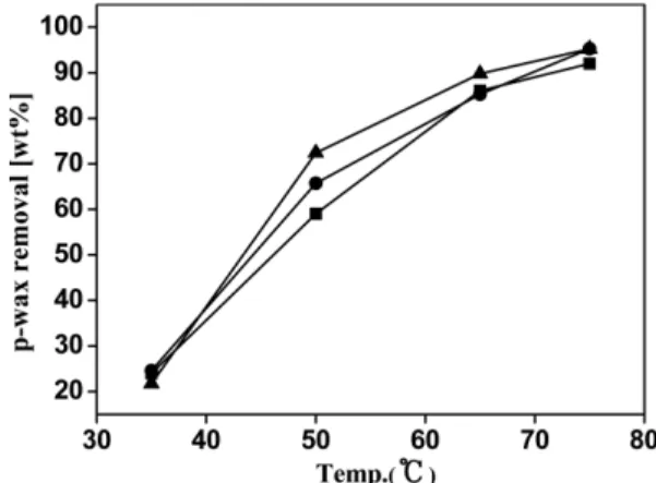
In a binder removal method using supercritical CO2, the main factor affecting the binder removal rate is the solubility between the binder and supercritical CO2. Supercritical CO2 can dissolve organic materials selec- tively via changes in its temperature and pressure, and the binder removal rate varies greatly depending on the changes in the conditions[16]. In this study, the binder removal rate of paraffin was calculated by changing the temperature and pressure of supercritical CO2. When the pressure was set to 15 MPa, the wax debinding rate was approximately 20 wt.%, regardless of temperature. This means that the solubility decreased, because the density needed to remove the paraffin was insufficient, even though the supercritical CO2 had characteristics of a supercritical fluid. However, Fig. 3 shows the pressure of the supercritical CO2 was 25 MPa, the binder removal rates were 65.7 wt.% and 95.2 wt% at temperatures of 50 and 75, respectively, showing that the rate depends on the temperature. The above results indicate that the large dif- ference of binder removal rates occurred because the
Fig. 3. Paraffin wax removal in dependence of temperature and pressure : (holding time at 2hr, ■: 20 Mpa, ●: 25 MPa, ▲: 30 MPa).
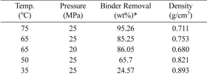
supercritical CO2, solvent could not easily dissolve the paraffin wax, which is not in a complete liquid state [17, 18]. Table 3 shows that the density and debinding rate of supercritical CO2 at each condition of the experi- ment, it was found that under the same pressure (25 MPa), when the temperature was low (35), the density was high; however, the binder removal rate was actually lower than when the temperature was high (75). This phenomenon seems to have occurred because it is diffi- cult to dissolve paraffin wax that is not completely liq- uid, even when the density of the solvent is high, since
the experiment was carried out at temperatures lower than the melting point of paraffin wax, as mentioned ear- lier. At or above the melting point, the binder removal rate tended to increase with increasing temperature.
3.2. Debinding process using thermal decomposition The injection molded object fabricated in this study was debinding a second time by thermal decomposition, in which the remaining binder was removed by capillary action at high temperature after removal of the paraffin wax, which is a low-molecular-weight binder, using supercritical CO2. In the microstructural analysis after supercritical CO2 debinding, no unusual observations were found as a result of the remaining high-molecular- weight binder. Subsequently, the microstructure was observed after removing all the remaining binder through thermal decomposition; pores were found between the aggregates inside the degreased object after thermal degreasing, as shown in Fig. 4(a). However, when degreas- ing with the supercritical CO2, pores between the aggre- gates were not found, as shown in Fig. 4(b). In this case, Table 3 Comparison of the binder removal with density of
supercritical CO2 [19]
Temp.
(oC)
Pressure (MPa)
Binder Removal (wt%)*
Density (g/cm3)
75 25 95.26 0.711
65 25 85.25 0.753
65 20 86.05 0.680
50 25 65.7 0.821
35 25 24.57 0.893
*Debinding time for 2hr
Fig. 4. The fracture surface morphologies of the brown part at 600oC & heat treatment (1700oC) PIMed SCF CO2 condition_20 MPa/65oC/2hr: (a) brown part, (c) heat treatment part SCF CO2 condition_20 MPa/50oC/2hr, (b) brown part, (d) heat treatment part.
the wax removal rate was relatively low, and only nano- sized pores between the powder particles inside an aggre- gate were observed. This was determined to be pore expansion caused by the inflation that occurs during wax debinding because the removal speed increases as a func- tion of the amount of wax removed. Based on this result, thermal treatment was performed for 10 min at 1700°C, which is below the sintering temperature (1750°C), to check how the pores present before sintering changed during the sintering densification process. As a result, many pores and defects were found after thermal debind- ing, as shown in Fig. 4(c); the pores between the aggre- gates are relatively large. This trend is expected to have a large influence on the optical transmittance rate since pores and defects remain in the final sintered object. In other words, if the removal rate of wax with a low- molecular-weight binder is fast, abnormally large pores are produced because the surrounding binders become more concentrated owing to capillary action as the pres- sure increases in the releasing direction of the wax.
Therefore, in this study, by adjusting the pressure and
temperature of supercritical CO2 when removing the wax, the debinding speed of initial binder was controlled to obtain the optimal debinding condition.
4.3 Analysis of shape and optical transmittance of polycrystalline alumina-sintered object
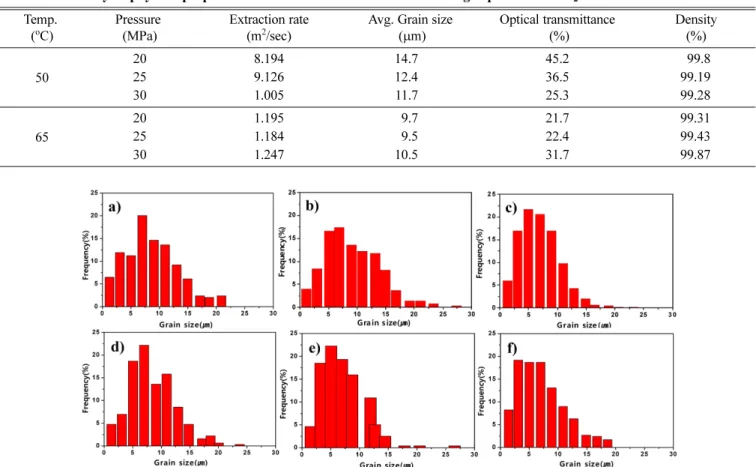
Table 4 shows the properties of the sintered object°Øs microstructure, grain size, and optical transmittance rate, which were measured by using a scanning electron microscope. In almost all the sintered objects, the den- sity was close to more than 99% of the theoretical den- sity. In the specimens that were debinding by applying respective pressures at a temperature of 65°C, which gave a uniform wax removal rate of 1.20 × 10⁻⁵ m2/s on average, no clear trend was found in the average grain size, the size distribution, or the optical transmittance rate of the sintered objects (Fig. 5). However, at a tempera- ture of 50°C, as the debinding rate of the wax removal, the average grain size and optical transmittance showed simultaneously increasing trends. At a temperature of 50°C and pressure of 30 MPa, where the binder removal
Table 4. Summary of physical properties at various extraction conditions using supercritical-CO2 Temp.
(oC)
Pressure (MPa)
Extraction rate (m2/sec)
Avg. Grain size (µm)
Optical transmittance (%)
Density (%)
50
20 8.194 14.7 45.2 99.8
25 9.126 12.4 36.5 99.19
30 1.005 11.7 25.3 99.28
65
20 1.195 9.7 21.7 99.31
25 1.184 9.5 22.4 99.43
30 1.247 10.5 31.7 99.87
Fig. 5. Comparison of grain-size distribution of high vacuum sintered specimen with Carbon dioxide(CO2) under various extraction;
flowed by temperature at 50oC: a) 20, b) 25, c) 30 MPa, and 65oC, d) 20, e) 25, f) 30 MPa.
rate was the fastest at 1.00 × 10⁻⁵ m2/s, the average grain size was 11.7 µm and the optical transmittance rate was 25.3%. At a temperature of 50°C and pressure of 20 MPa, where the binder removal rate was the lowest at 8.19 × 10⁻⁶ m2/s, the largest average grain size and opti- cal transmittance rate of14.7 µm and 45.2%, respec- tively, were confirmed. These results can be interpreted to have occurred because the densified sintered object, i.e., the degreased object subjected to thermal debinding, was formed without pores when sintered at high tempera- ture. Furthermore, the existence of many large grains having a maximum average size of 18.3 µm (+3.6 µm) can be viewed as a reason for the improvement of the optical transmittance rate. In Fig. 6(a), where the highest optical transmittance rate of 45% is shown, the grain sizes were small or evenly formed without defects. In Fig. 6(d), which shows optical transmittance rate of 21.7% due to the micro-pores inside the sintered object and defects around the grains, grains with small diame- ters were found, which caused the light scattering and diffraction that led to the optical transmittance rate.
5. Conclusions
1) In the powder injection-molding process, where the supercritical debinding process is applied, the following conclusions were derived from the experiment results and the discussion of the research on the correlation of the grain diameter and the optical transmittance rate of the translucent alumina-sintered object.
2) By changing the pressure and temperature of the supercritical CO2, the removal rate of the wax, which is the initial binder, was controlled. When the pressure was increased, the removal rate increased in the releasing direction of the wax, and it became more concentrated owing to the capillary action of the surrounding binder.
This produced abnormally large pores in the molded object, and it was confirmed that the expansion of pores occurred simultaneously owing to degreasing. Based on these results, it was found that presence of micro-pores before sintering lead to pores and defects in the final sin- tered object, thereby affecting the optical transmittance.
3) In the powder injection molding process using supercritical CO2 debinding, the analysis results of opti- cal transmittance as a function of the grains in the sin- tered translucent alumina object confirmed that the abnormally large pores produced by the fast removal of the initial binder also remained in the final sintered object. In addition, the transmittance rate decreased con- siderably because of defects and micro pores produced in the grains. In other words, with respect to the grain fac- tor that has the most important influence on the optical transmittance of translucent alumina, priority should be given to the removal of pores and defects, as well as the impurities around the grains, rather than to the size of the polycrystalline grains.
Acknowledgements
This work was carried out using the PIM equipment Fig. 6. Grain size distribution of sintered specimens debound at 50oC at: a) 20, b) 25, and c) 30 MPa, and 65oC at d) 20, e) 25, f) 30 MPa.
including supercritical fluid extraction from KINORI Co., Ltd.
References
[1] J. Y. Roh, J. Kwon, C. S. Lee and J. S. Choi: Ceram. Int., 37 (2011) 321.
[2] D. S. Kim, J. H. Lee, R. J. Sung, S. W. Kim, H. S. Kim and J. S. Park: J. Eur. Ceram. Soc., 27 (2007) 3629.
[3] T. Chartier, M. Ferrato and J. B. Baumard: J. Eur. Ceram.
Soc., 15 (1995) 899.
[4] J. Crank: Oxford University Press, Oxford, 44 (1977).
[5] T. Shimizu and S. Mochizuki: Mechanical Engineering Laboratory, 51 (1997) 41.
[6] M. Rei, E. C. Milke, R. M. Gomes, L. Schaeffer and J. K.
Souza: Mater. Lett., 52 (2002) 360.
[7] Y. H. Kim, J. S. Lim, Y. W. Lee and S. N. Kim: J. Korean Powder Metall. Inst., 8 (2001) 91.
[8] O. Kajimoto: Chem. Rev., 99 (1999) 355.
[9] S. C. Tucker: Chem. Rev., 99 (1999) 391.
[10] M. D. Lugue de Castro and M. Valcarcel M. T. Tena:
Spinger-verlag, 31 (1994) 150.
[11] P. G. Shewmon: Diffusion in Solids, McGraw-Hill, 18 (1963).
[12] Y. Sato, T. Takikawa, S. Takishima and H. Masuoka: J.
Supercrit. Fluids, 19 (2001) 187.
[13] M. L. Lee and K. E. Markides: Chromatography conf.
Inc. Provo, UT (1990).
[14] A. Ferri, M. Banchero, L. Manna and S. Sicardi: J. of Supercrit. Fluids, 31 (2004) 133.
[15] Q. Li, Z. Zhang and C. Zhong: J. of Chem. Eng. Data, 48 (2003) 61.
[16] D. E. Knox: Int. Res. J. Pure Appl. Chem., 46 (2011) 1255.
[17] E. Nishikawa, N. Wakao and N. Nakashima: J. of Super- crit. Fluids, 4 (1991) 265.
[18] D. E. Knox: Int. Res. J. Pure. Appl. Chem., 46 (2011) 1255.
[19] S. Angus, A. Armstrong and K. M. de Reuk: Pergamon, Oxford (1976) 3.
![Table 1. Comparative physical properties of gas, supercritical fluid, liquid [13]](https://thumb-ap.123doks.com/thumbv2/123dokinfo/4916660.536972/2.892.163.726.125.350/table-comparative-physical-properties-gas-supercritical-fluid-liquid.webp)