Chan-Bae Park·Hyung-Woo Lee· Byung-Song Lee
1. 서 론
회전형전동기를 이용하여기계적인추진력을기어와바 퀴로전달하여레일위를달리는기존의철도시스템에서발 생하는여러 가지문제점들을개선하기 위하여동력변환장 치없이직선 추진력을직접얻을수 있는선형유도전동기
(Linear Induction Motor, LIM)
를 이용한 철도응용 분야에관심을두고지속적인연구및상용화가진행되고있다
. LIM
을추진시스템으로채택한 대표적철도응용분야는 자기부
상열차와리니어지하철및경전철분야이며
, Fig. 1
은국내용인에건설중인용인경전철의
LIM
추진시스템과일본리 니어메트로차량의대차하부에부착된LIM
추진시스템을 보여준다.
철도차량 추진시스템용LIM
에있어서,
일반적으로
, LIM
의1
차측은차량의대차, 2
차측은선로구축물에취부되는구조를가진다
. LIM
은 구조상으로1
차측길이방향이 유한하여입
,
출구단에서의자속이불균형하게되는종 방향 단부효과와1
차측이동자계에의해2
차측에유기되는 와전류성분중추력를발생시키지못하는성분이존재하기 때문에유효공극 길이의증가와자속의왜곡등을유발시 키는 횡방향단부효과가발생하게되며,
또한1
차측과2
차측사이에서수직력도발생하게된다
[1].
그러므로LIM
을정확히해석하기위해서는 이들현상들이모두명확하게고려 되어야 하는 어려움이 있다
.
일반적으로
LIM
의 설계결과를검증하기 위하여FEM
을 이용한수치해석기법및등가회로법을이용한수학적방법 이 주로이용된다.
본연구에서는 철도차량용LIM
축소-
회 전형 모델의기본설계결과를검증하기위하여LIM
의등 가회로법을이용한특성계산을수행하고자한다. LIM
의경우
,
등가회로상의 파라미터는LIM
의전기자코어와2
차측 도체판의형상및 공극에대한함수로써표현이가능하다.
즉 전기자코어와
2
차측도체판의형상및 공극 변경에의 해선형유도전동기의특성이크게달라질수있다는것을의 AbstractAuthors conducted a deduction and characteristic calculation of the some parameters using a magnetic equiva- lent circuit method to verify a basic design result of a rotary-typed small-scaled linear induction motor for a railway transit.
In a LIM, it is possible to express the parameters of the magnetic equivalent circuit into a function of the shape of the sec- ondary aluminium plate and the airgap between the LIM primary core and the secondary aluminium plate. It means that the LIM properties can be changed considerably by the shape of the secondary aluminium plate and the airgap between the LIM primary core and the secondary aluminium plate. So, authors analyzed a tendency of changes of the magnetic equivalent circuit parameters and the LIM characteristics by changing of the airgap, the thickness of the secondary aluminium plate and the overhang length and shape of a rotary-typed small-scaled LIM, and accomplished a basic research to develop a real- scaled LIM for a railway transit.
Keywords
: Linear-metro, Linear induction motor, Rotary-typed small-scaled model, Magnetic equivalent circuit
초 록 철도차량용 선형유도전동기
(Linear Induction Motor, LIM)
축소-
회전형 모델의 기본설계 결과를 검증하 기 위하여LIM
의 자기등가회로법을 이용한 파라미터도출 및 특성계산을 수행하였다. LIM
의 경우,
자기등가회 로상의 파라미터는LIM
의 전기자 코어와2
차측알루미늄 도체판의 형상 및 공극에 대한 함수로써 표현이 가능 하다.
즉 전기자 코어와2
차측 알루미늄 도체판의 형상 및 공극 변경에 의해LIM
의 특성이 크게 달라질 수 있 다는 것을 의미한다.
따라서 본 연구에서는 철도차량용LIM
축소-
회전형 모델의 공극, 2
차측AL-Plate
의 두께,
오버행 길이
,
형상 변경에 따른LIM
축소-
회전형 모델의 자기등가회로 파라미터 및 특성의 변화 추세를 분석하여
,
철도차량용 실모델LIM
개발을 위한 기초 연구를 수행하였다.
주요어 : 리니어메트로
,
선형유도전동기,
축소-
회전형모델,
자기등가회로†교신저자 : 한국철도기술연구원주행추진연구실
E-mail : [email protected]
1한국철도기술연구원주행추진연구실
미한다
.
따라서 본논문에서는 철도차량용LIM
축소-
회전 형 모델의 공극, 2
차측Al Plate
의 두께,
오버행 길이,
형 상 변경에따른LIM
의 등가회로 파라미터및 특성의 변화 추세를분석하고,
제어시뮬레이션S/W
를이용하여LIM
의 도출된등가회로파라미터의 신뢰도검증을수행하고자 한 다.
2. LIM 축소모델의 설계
철도차량추진시스템용실모델
LIM
제작에앞서서회전형축소모델
LIM
및 성능시험기를이론적방법에의해 설계하였다
.
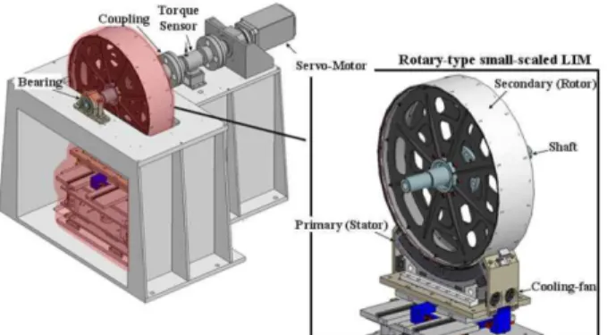
그림2
는 회전형축소모델LIM
및성능시험기개념도와제작중인시제품을보여준다
.
그림에서와같이LIM
의편측식
Short Primary
를 정지형타입으로, 2
차측 벡요크및리액션플레이트를지름
1m
의회전형타입으로설계하였으며
, LIM
의 공극은5mm
로 산정하였다. LIM
의 정격용량은
10kW
이고,
극수는실모델의경우단부효과영향도를고려하여
8
극을선정하였지만본논문의대상인축소모델LIM
의 경우
Primary Unit
의길이(678mm)
를고려하여4
극으로 설계하였다. 2
차측리액션플레이트의형상은비용대비성능을 고려하여
1.2
오버행을갖는Semi-cap
방식으로 선정하였으며
,
두께는5mm
로선정하였다.
도표1
은회전형축소모델
LIM
및 성능시험기의 설계 결과를 보여준다.
3. 등가회로 파라미터 및 특성 계산 기법
일반적으로선형유도전동기의기본설계결과를검증하기 위하여등가회로법을이용한수학적방법이주로이용된다
.
철도차량용 선형유도전동기의축소
-
회전형모델의 기본설 계 결과를검증하기위하여 본연구에서는선형유도전동기 의 등가회로법을이용한특성계산을수행하였다[4,5].
선형 유도전동기의전기회로와 자기회로의 결합도를나타내는Goodness factor
는 식(1)
과 같이나타낼 수 있으며, 2
차측 의 도체폭을 고려한등가도전율및Russell Norsworthy
계수는 식
(2), (3)
과 같이 나타낼 수 있다.
(1) (2) (3)
G 2µ0fτ2σed πgmag ---
= σe=kRNσ kRN1 tanh πh 2τ( ⁄ )
πh 2τ⁄
--- 1 tanh πh 2τ{ – ( ⁄ )tanh πc τ( ⁄ )}
= Fig. 1
Configuration Linear induction motor [2,3]
Table 1
Design results of the rotary-typed small-scaled LIM
Item Specification
Continuous Rated Output Power 10kW
DC-link Voltage 362V
Rated Frequency 37Hz
Rated Slip 0.2
Rated Speed 8.5m/s
Phase / Poles 3 / 4
Slots/Pole/Phase 4
Air-gap 5mm
Pole Pitch / Slot Pitch 144 / 12mm Series Turns per Phase 112 Primary Core Length / Stack Width 678 / 200mm
Primary Unit Weight 78kg
Al Plate Thickness 5mm
Fig. 2
Details of the rotary-typed small-scaled LIM and its
performance tester
Fig. 3
은선형유도전동기의정상상태등가회로를나타내며,
등가회로를통하여고정자 전류가얼마만큼의자속 전류와 토크전류
(2
차측전류)
로분배되는가는주로슬립(S)
에의해결정됨을알수있다
[1].
선형유도전동기의등가회로파라미터는식
(4) ~
식(11)
을이용하여계산할수있으며, Table 1
에설계된 선형유도전동기의등가회로파라미터계산결과 를정리하였다.
여기서리액턴스는인던턴스로변환하였다.
Fig. 3
Equivalent circuit of the LIM
(4)
(5)
(6)
(7)
(8)
앞서계산한등가회로파라미터를이용하여
1
차측전류I
1계산이 가능하며
,
식(12), (13)
을 이용하여 설계된 선형유도전동기의 추진력 및 수직력 특성을 살펴보았다
. (12)
(13)
4. 등가회로 파라미터의 특성 분석
선형유도전동기의경우
,
등가회로상의파라미터는선형유 도전동기의 전기자코어와2
차측 도체판의형상및공극에 Table 1Calculation results of parameters of the equivalent circuit
LIM Parameters Value
Primary Resistance 0.18Ω
Primary Leakage Inductance 6.19mH Excitation Inductance 9.47mH Secondary Resistance 0.333Ω Secondary Leakage Inductance 0.48mH
R1 1
σc ---2 h 1( + ce)
Iph ---JcNph
=
X1 8πµofwNph2
--- λp s⎝⎛1 3+p---⎠⎞ λ+ d h q--- λ+ elce
⎩ ⎭
⎨ ⎬
⎧ ⎫
=
λs 1
12--- hs ws --- 1 3k( + p)
=
λd
5 gmag ws ---
⎝ ⎠
⎛ ⎞
5 4 gmag ws ---
⎝ ⎠
⎛ ⎞
+ ---
=
λe=0.3 3k( p–1)
여기서
,
R1: 1
차측저항lce
:
전기자코일의End connection
길이 σc:
전기자코일의도전율Jc
:
전기자코일의전류밀도Nph
: 1
상의직렬턴수X1
: 1
차측누설리액턴스p
:
극수hs
:
슬롯깊이ws
:
슬롯폭kp
:
슬롯피치Factor
kw
:
권선계수g
:
기계적 공극Xm
:
자화리액턴스R2
: 2
차측저항X2
: 2
차측누설리액턴스여기서
,
Fx:
선형유도전동기의 추진력I1
: 1
차 전류S
:
슬립Fn
:
선형유도전동기의 수직력Jm
: 1
차측 코일의 등가 선전류밀도 Fx 3I12R22τ f S 1
SG---
⎝ ⎠
⎛ ⎞2+1
⎩ ⎭
⎨ ⎬
⎧ ⎫
---
=
Fn pτ2 π2
--- µ0Jm2(h g d+ + ) gmag2 (1 S+ 2G2)
--- 1 π–⎝⎛---gτ magSG⎠⎞2
⎩ ⎭
⎨ ⎬
⎧ ⎫
⋅
=
: 2
차측도체판의 오버행대한함수로써표현이가능하다
.
즉전기자코어와2
차측도 체판의형상및 공극변경에의해선형유도전동기의특성이 크게달라질수 있다는것을의미하며,
본 연구에서는앞에 서 설계된선형유도전동기의공극, 2
차측Al Plate
의 두께,
오버행길이
,
형상변경에따른선형유도전동기의등가회로 파라미터 및 특성의 변경 추이를 분석하였다.
4.1. 공극에 따른 파라미터 특성 분석
일반적으로철도차량에적용이가능한선형유도전동기의 경우기계적공극이회전형유도전동기에비해상대적으로크 기 때문에공극의변화에따른특성변화분석이중요하다
. Fig. 4
와Fig. 5
는공극이3mm, 5mm, 7mm
일 때의등가회 로파라미터분석결과를보여준다.
선형유도전동기의2
차측누설리액턴스와자화리액턴스가공극의변화에따라크
게 변함을알 수 있다
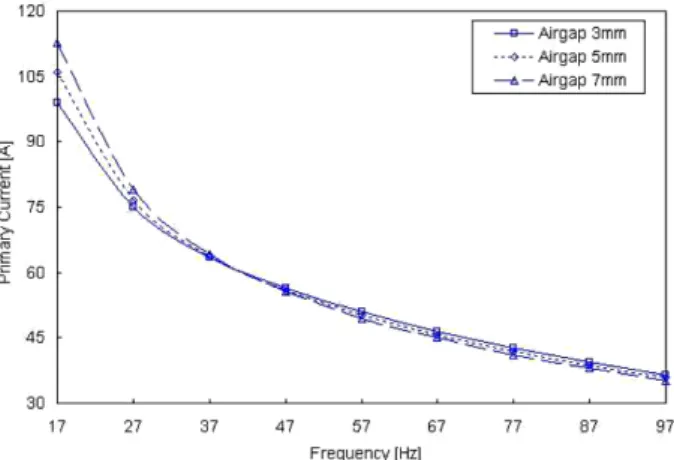
. Fig. 6
은선형유도전동기의 공극변화에따른입력전류의변화특성을보여주며
, Fig. 7
은추진력과수직력의변화특성을보여준다
. Fig. 10
에서알수 있듯이
,
추진력과수직력특성은저속영역에서공극변화에 대해 더욱 민감해짐을 알 수 있다.
4.2. 2차측 Al Plate 두께에 따른 파라미터 특성 분석 일반적으로철도차량용선형유도전동기의
2
차측도체판은Back-Iron
위에경계면을이루며장착된다.
리니어전철에적용할 경우
,
선형유도전동기의2
차측도체판의재질은역구 내에서는 효율을향상시키기 위하여때때로 구리(Cu)
를사용하며
,
일반구간에서는알루미늄(Al)
을사용한다.
이러한 선형유도전동기의2
차측Al Plate
의 두께가변하면선형유도전동기의전기회로와자기회로의결합도를나타내는
Good-
ness factor
가변하기때문에결과적으로등가회로상의각각의 파라미터가변하여특성을영향을 주게된다
[6]. Fig. 8
은
2
차측Al Plate
의 두께가4mm, 5mm, 6mm
일때의등가회로파라미터분석결과를보여준다
.
그림에서보듯선형 유도전동기의2
차측저항및 누설리액턴스와 자화리액턴스가크게 변함을알수있다
. Fig. 9
는 선형유도전동기의2
차측
Al Plate
의두께변화에따른입력전류의변화특성을보여주며
, Fig. 10
은추진력과수직력의변화특성을보여준다.
4.3. Al Plate 오버행 길이에 따른 파라미터 특성 분석 철도차량용선형유도전동기에서효율을향상시키기위해 서보통
1
차측코어의폭보다2
차측도체폭이넓게설계,
제 Fig. 4Characteristic transitions of R1, R2, X2 due to the change
the air-gap(3mm, 5mm, 7mm)
Fig. 5
Characteristic transitions of X1, Xm due to the change of the air-gap(3mm, 5mm, 7mm)
Fig. 6
Characteristic transitions of the primary input current due to the change of the air-gap(3mm, 5mm, 7mm)
Fig. 7
Characteristic transitions of the thrust and normal forces due
the change of the air-gap(3mm, 5mm, 7mm)
작되는데
,
이때 생기는2
차측도체판의여유부분을오버행 이라한다.
일반적으로선형유도전동기에서오버행을증가 시키면선형유도전동기진행방향으로의와전류성분을줄일수는 있으나와전류 경로가길어져서
2
차 저항을증가시키 므로 어느정도 오버행길이이상에서는횡방향효과저감 을 기대할수없고,
재료비만증가되므로적당한오버행길이의 산출이중요하다
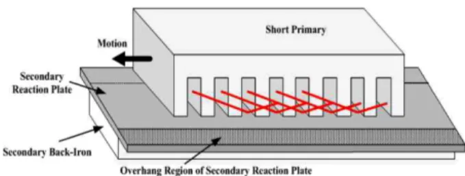
[7]. Fig. 11
은선형유도전동기에서의2
차측Al Plate
의 오버행을보여주며, Fig. 12
는Al Plate
오 버행길이의변화에따른선형유도전동기의횡방향효과저 감 추이 특성을보여준다.
그림을통하여알수 있듯이,
오 버행 길이가늘어날수록횡방향특성개선폭이 점점떨어지는경향을 보임을알 수 있다
. Fig. 13
은오버행 비가1,
1.1, 1.2, 1.3
일 때의등가회로 파라미터중2
차측저항분석 결과를보여준다
.
그림에서보듯 오버행비가변함에따 Fig. 8Characteristic transitions of X1, Xm due to the change of
the thickness of the secondary Al Plate(4mm, 5mm, 6mm)
Fig. 9
Characteristic transitions of the primary current due to the change of the thickness of the secondary Al Plate(4mm, 5mm, 6mm)
Fig. 10
Characteristic transitions of the thrust and normal forces due to the change of the thickness of the secondary Al Plate(4mm, 5mm, 6mm)
Fig. 12
Improvment of the transverse edge effect due to the change of the overhang length of the secondary Al Plate
Fig. 13
Characteristic transitions of R2 due to the change of the
overhang length of the secondary Al Plate
라 선형유도전동기의
2
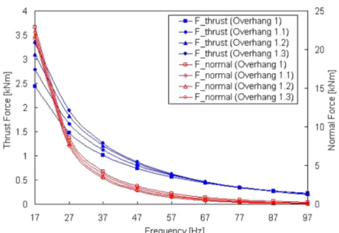
차측저항이크게변함을 알 수 있 다. Fig. 14
는선형유도전동기의2
차측Al Plate
의오버행비 변화에따른입력전류의변화특성을보여주며, Fig. 15
는추 진력과 수직력의 변화 특성을 보여준다.
4.4. Al Plate 오버행 형상에 따른 파라미터 특성 분석 일반적으로선형유도전동기의횡방향효과는
2
차측 도체판의형상에따라결정되는데
, 2
차측도체판의오버행형상 에따라2
차측도체판에서의등가도전율이크게달라진다.
즉
,
횡방향효과의영향으로다른형상의도체판을 가지고 있는선형유도전동기는그성능특성 또한다르게된다.
본연구에서는
3
가지형태(Flat-plate type, Semi-cap type, Full-
cap type)
의오버행 형상을 고려하였으며, Fig. 16
은 본 연구에서고려된
2
차측Al Plate
다양한오버행형상을보여준다
. Fig. 17
은오버행형상에따른등가회로파라미터중2
차측저항의분석결과를보여준다.
그림에서보듯Flat Plat
형상에비해
Semi-cap, Full-cap
형상의2
차측저항이더 작아짐을 알 수 있다
. Full-cap
형상을 적용할 경우Flat-cap,
Semi-cap
에 비해서LIM
운행시2
차측에더큰유기전압을얻을수 있으며
,
결국더큰 추진력을얻는 것이가능해진 Fig. 14Characteristic transitions of the primary current due to the
change of the overhang length of the secondary Al Plate
Fig. 15
Characteristic transitions of the thrust and normal forces due to the change of the overhang length of the secondary Al Plate
Fig. 16
Secondary Al reaction plate of the various type on the LIM
Fig. 17
Characteristic transitions of R2 due to the change of the overhang shape of the secondary Al Plate
Fig. 18
Characteristic transitions of the primary current due to the change of the overhang shape of the secondary Al Plate
Fig. 19
Characteristic transitions of the thrust and normal forces
due to the change of the overhang shape of the secondary
Al Plate
다
. Fig. 18
은선형유도전동기의2
차측Al Plate
의오버행형 상변화에따른입력전류의변화 특성을보여주며, Fig. 19
는 추진력과 수직력의 변화 특성을 보여준다
.
5. 등가회로 파라미터의 신뢰도 검증본연구에서도출된
LIM
의 등가회로파라미터및특성해 석 결과의 신뢰도 검증을 위하여 제어 시뮬레이션S/
W(Simplorer)
를이용하여LIM
모델링및특성분석을수행하였다
.
그림20
은슬립주파수제어알고리즘을적용한LIM
제어모델을보여준다
[8,9]. LIM
은 기본적으로공극5mm,
Semi-cap
타입의AL Plate
두께5mm,
오버행1.2
로모델링 하였으며,
기준전류는65A
까지적용된알고리즘을통해 서 서히증가하고일정 속도이후에전류지령을낮추어고속 영역에서의알고리즘안정도를확보했다.
그림21
은시뮬레이션에의한
LIM
모델의기준전류및 실제전류,
추진력,
속도결과파형을보여준다
.
그림21
에서 알수 있듯이,
전류 지령에대해전류제어가잘 되고있으며,
추진력역시전 류제어결과와유사한 경향을보임을알 수있다.
또한발생추진력은
65A
전류에서약1,000N
으로설계에의한 추진력
1,125N
과약11%
정도의오차가발생하였다.
결론적으로본 연구에서도출된
LIM
의 등가회로파라미터및 특성해석기법을통하여
LIM
축소-
회전형시험모델의정확한성능예측이가능할것으로판단되며
,
향후제작된LIM
축 소-
회전형시제품에서의실시험을통하여LIM
의정확한특성 파라미터 도출 및 검증 연구를 수행할 계획이다
.
6. 결 론도시철도차량에 적용하기위한대용량
LIM
설계/
분석하 는데있어서,
구조적으로발생하는종방향,
횡방향단부효과 및수직력등을모두명확하게고려하는것은쉽지않다.
일 반적으로LIM
의 설계결과를검증하기 위하여FEM
을 이 용한수치해석기법및 등가회로법을이용한수학적방법이 주로이용된다.
본 연구에서는철도차량용LIM
축소-
회전 형 모델의기본설계결과를검증하기위하여LIM
의 등가 회로법을이용한특성 계산을수행하였다. LIM
의경우,
등 가회로상의파라미터는LIM
의전기자코어와2
차측도체판 의 형상및공극에대한 함수로써표현이가능하며,
전기자 코어와2
차측도체판의형상및 공극변경에의해 선형유 도전동기의특성이크게 달라질수있다.
따라서본논문에 서는철도차량용LIM
축소-
회전형모델의공극, 2
차측Al
Plate
의 두께,
오버행 길이,
형상변경에따른LIM
의 등가회로파라미터및 입력전류
,
추력,
수직력특성의 변화추 세를분석하였으며,
도출된등가회로파라미터및 특성해석결과의신뢰도검증을위하여제어시뮬레이션
S/W
를이용하여
LIM
모델링및 특성분석을수행하였다.
전체적으로LIM
의등가회로파라미터변화에대해저속영역에서민감하게반응하는 것을본연구결과를 통해알 수 있었다
.
향후
LIM
축소-
회전형시제품에서의실 시험에통하여LIM
의 정확한 특성파라미터도출 및 검증연구를수행할 계 획이며
,
실제철도차량추진용LIM
을개발 시본연구결과 를 활용할 수 있을 것으로 기대된다.
참고문헌
[1] C.B. Park, B.S. Lee, J. Lee (2009) Dynamic Characteristics Analysis Considering the Effect of the Vortexes of Flux in a LIM for Railway Propulsion System, Journal of the Korean Society for Railway, 12(3), pp. 437-442.
[2] H.-W. Lee, S. Lee, C. Park, J. Lee, et al. (2008) Characteristic Analysis of a Linear Induction Motor for a Lightweight Train according to Various Secondary Schemes, International Jour- nal of Railway, 1(1), pp. 6-11.
[3] Japan Subway Association (2004) Linear Metro System, Japan Subway Association, pp. 1-28.
[4] I. Boldea, S.A. Nasar (2001) Linear motion electromagnetic Fig. 21
The reference current vs. real current, thrust force and
speed characteristics of the LIM model
devices, Taylor&Francis, NY, pp. 44-72.
[5] Jacek F. Gieras (1994) Linear induction drives, Clarendon, Oxford, pp. 12-16.
[6] D.J. de Groot (1993) Dimensional analysis of the linear induc- tion motor, IEE Proceedings-B, 140(4), pp. 273-280.
[7] R.M. Pai, Ion Boldea, S.A. Nasar (1988) A Complete Equiva- lent Circuit of a Linear Induction Motor with Sheet Second- ary, IEEE Trans. on Magnetics, 24(1), pp. 639-654.
[8] C.-B. Park, B.-S. Lee, H.-W. Lee, S.-Y. Kwon, et al. (2008)
Air-gap Control System of a Linear Induction Motor for a Railway Transit, Proceedings of the 2008 International Con- ference on Electrical Machines, Portugal, pp. 1-4.
[9] H.-J. Park, S.-Y. Kwon, B.-S. Lee, H.-W. Lee, et al. (2008) Development of the 750V Linear propulsion system for the urban railway application, Korea Railroad Research institute, KRRI Research 08-027.
접수일(2009년 11월 25일), 수정일(2010년 7월 28일), 게재확정일(2010년 8월 5일)
![Fig. 3 은 선형유도전동기의 정상상태 등가회로를 나타내며 , 등가회로를 통하여 고정자 전류가 얼마만큼의 자속 전류와 토크 전류 (2 차측 전류 ) 로 분배되는가는 주로 슬립 (S) 에 의해 결정됨을 알 수 있다 [1]](https://thumb-ap.123doks.com/thumbv2/123dokinfo/5372163.406572/3.892.463.807.177.692/선형유도전동기의-정상상태-등가회로를-나타내며-등가회로를-얼마만큼의-분배되는가는-결정됨을.webp)