Effect of the Blade Leading Edge on the Performance of a Centrifugal Compressor
Chu Leizhe, Du Jianyi, Zhao Xiaolu, Xu Jianzhong
Institute of Engineering Thermophysics, Chinese Academy of Science No.12B Zhongguancun Road, Beijing 100080, P. R. China
Email: [email protected]
Keywords: leading edge, centrifugal compressor, numerical simulation
Abstract
Three different geometry shapes of the blade leading edge in a centrifugal compressor were investigated in this paper. Numerical simulation was done to analyze the effect of the leading edge shape on the performance of the centrifugal compressor. The result shows that compared to the blunt leading edge, the circular leading edge will raise the chocking mass flow. The pressure ratio and efficiency will increase obviously. Using elliptical leading edge will get a further improvement on the performance than circular leading edge. The analysis of the flow field shows that the leading edge often causes flow separation near the inlet; using circular leading edge and elliptical leading edge will reduce the separation. What’s more, using circular and elliptical leading edge will also reduce the wake loss near the outlet of the impeller. In a centrifugal compressor, using circular or elliptical leading edge on the splitter will improve the pressure loading distribution of main blade near the position of the splitter leading, which will increase the pressure ratio.
Introduction
The leading edge of the compressor blade is an important factor in the design of compressor blade.
When the incident angle changes, different kinds of leading edge will cause different affects on the flow near the leading edge, which will affects the performance of the compressor significantly. So to investigate the effect of leading edge geometry shape on the performance and flow field will be helpful to the compressor design. The leading edge geometry of blade has been paid a lot of attention. Valraevens and Cumpsty(1993)investigated the effect of circular and elliptical leading edge on the flow, and pointed out that the elliptical leading edge can restrain the development of boundary layer, increase the incident angle range. Lu Hongzhi and Xu Liping designed a circular leading edge with flat which improves the performance and reduce the difficulty in producing. In this paper, different kinds of leading edge are used in a centrifugal compressor, and numerical simulation is used to investigate the effect on the performance and flow.
Research object and numerical method
In this paper, a high pressure ratio centrifugal compressor is investigated, including impeller with splitter and vaned diffuser. Three different kinds of blade leading edge geometry shapes are applied to the impeller, while containing the other geometry unchanged. The three kinds of leading edge are separately blunt, circle and ellipse with a/b=2.
Numerical simulation is undertaken to study the effect of leading edge on stage performance and flow in the centrifugal compressor. The geometry of the centrifugal compressor stage that is investigated is shown in Figure 1.
Fig.1 geometry of the centrifugal compressor
Fig.2 grid of computation
In this paper, one channel of the compressor is chosen to undertake steady computation. The performance curves are obtained by escalating the outlet pressure of the compressor. Multigrid is used to get a better quantity grid. H-type grid is applied except the butterfly grid in the tip clearance of impeller. The
total number of grid is about 0.6million. The grid is shown in Figure 2. The computation in this paper uses the CFD software Numeca Fine/Turbo. Spalart- Allmaras turbulence model is used in the computation.
As for the boundary condition, total pressure, total temperature and flow angle are given at the inlet, and average pressure at the outlet.
Results and analysis
Performance of compressor stage
In the computation, lower outlet pressure is given at first, and then increasing the outlet pressure until the computation can’t obtain convergence. Fig.3 is the performance curves of three kinds of compressors. It is shown that compared to the blunt leading edge, the curves of circular leading edge and elliptical leading edge move to the right side, and the elliptical leading edge is more evident. The chock mass flow of circular leading edge is higher than that of blunt leading edge;
it increases from 1.174kg/s to 1.198kg/s which are about 2%, and the chock mass flow of elliptical leading edge increases to 1.224kg/s. It can be find from the mass flow/efficiency curve that the peak efficiency of circular leading edge is higher than blunt leading edge about 1.5percent, and that of elliptical leading edge is higher than circular leading edge about 1.5percent. From the mass flow/pressure ratio curves, the pressure ratio of circular leading edge increases significantly from blunt leading edge to circular leading edge and elliptical leading edge.
Fig.3 performance curves
Flow field analysis
To analyze the effect of leading edge on the flow in centrifugal compressor, three operation point A, B and C which are near peak point on the efficiency curves of Fig.3 are chosen to do flow analysis.
Fig.4 the meridian contour
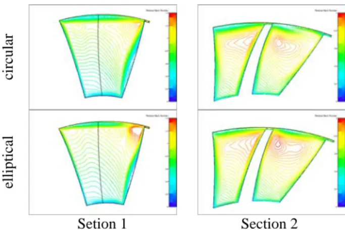
The s3 sections near the leading edge of main blade, near the leading edge of splitter and the outlet of impeller are chosen to analyze the flow in the impeller, which are marked as section 1,2 and 3 in fig.4. Fig.5 is relative Mach number distribution of s3 section near the leading edge of blade and splitter. It shows that there is a separation at the suction side near the leading edge of main blade, while there isn’t clear separation neat the leading edge of splitter. The Mach number distribution of section 1 shows that compared to the blunt leading edge, the circular and elliptical leading edge will reduce the separation near the main blade leading edge, and the low speed area near the shroud also reduces. As for the section 2, when using blunt leading edge, the Mach number of two channels is quite different, the Mach number of the channel between the blade pressure side and splitter suction side is higher than that of the channel between main blade suction side and splitter pressure side. Using circular and elliptical leading edge will improve the flow of the two channels, which makes the Mach number distribution more uniform. From the distribution of Mach number, is can also be found that using different kinds of leading edge will cause obvious effect on the flow of the clearance. Circular leading edge will reduce the low speed area near the clearance, and the elliptical leading edge will improve the flow further.
Blunt
circular elliptical
Setion 1 Section 2
Fig.5 relative Mach number distribution Fig.6 is 10%, 50% and 90%span entropy distribution of three cases. It shows that the loss of the impeller is mainly caused by the boundary layer of the blade and the wake near the outlet of the impeller. The loss is less near the hub, and near the shroud the loss grows a lot because of the effect of the clearance leakage. At the 10%span, there are separation bubbles at both pressure side and suction side of the blade and
splitter with the blunt leading edge, and the separation bubbles reattach on the blade surface downstream. As for the circular leading edge, there are only separation bubbles evidently on the blade, and the bubbles reattach on the blade rapidly, and the separation bubbles are smaller than that of blunt leading edge.
The loss near the trail edge of the blade also reduces.
When the leading edge is elliptical, there are no evident separation bubbles near the leading edge at both blade and splitter. At all the three cases, the separation bubbles near the leading edge all increase significantly along spanwise; at 50%span, the distance of the reattachment of the separation is larger than at 10%span, and at 90%span, the separation grows to the middle of channel and mixing with the wake near the outlet, which causes great loss in the impeller channel.
From the distribution of the entropy, it shows that the decrease of the loss near the leading edge is not the only one reason that improves the efficiency, but the improvement of the wake at the outlet is also an important factor.
Figure 6 distribution of entropy(from left to right:blunt,circle,ellipse;from top to bottom:10%,50%,90%span
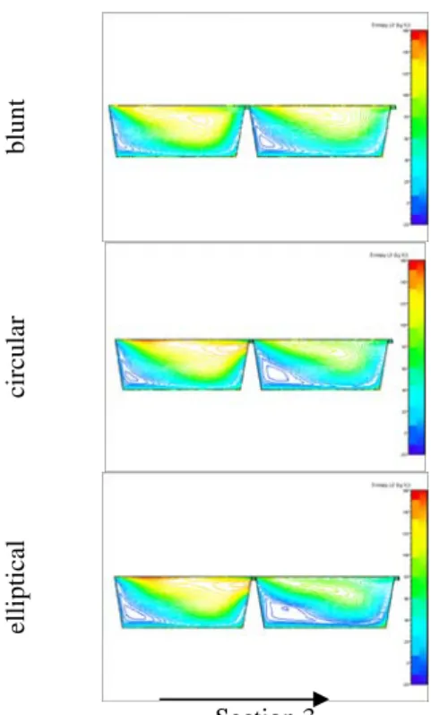
Fig.7 is the distribution of entropy of s3 section at the outlet of impeller. It shows that the main loss is the wake loss near the shroud and suction side corner.
The loss of the channel between main blade pressure side and splitter suction side is much higher than that of the other channel. Changing the leading edge causes little effect on the channel between main blade
pressure side and splitter suction side, but affects the other channel a lot. Compared to the blunt leading edge, the circular leading edge will reduce the loss of the channel between main blade suction side and splitter pressure side, and the elliptical leading edge will reduce the loss further.
bluntcircular elliptical
Section 3
Fig.7 entropy distribution at outlet of impeller Fig.8 is the distribution of static pressure on the blade surface. The pressure load of the blade increases along spanwise, and the main pressure load lies on the downstream blade. At 10%span, the
distribution of pressure changes a little. At 50%span, when the leading edge is blunt, at the position of the leading edge, the load of blade is very small, and the load of blade is smaller than that of the splitter evidently. When the leading edge is circular, the distribution of pressure is more uniform, the load of splitter is similar with that of the blade. As for the elliptical leading edge, the distribution is similar with that of circular leading edge, but the pressure load of the blade is higher than that of the splitter a little which will increase the pressure ratio. When the leading edge is blunt, from 10% to 90%span, the pressure load of the blade grows more and more nonuniform; at 90%span, the pressure load is very small near the leading edge of the splitter, but larger near the outlet of the impeller. When using the circular leading edge, the distribution of pressure is more uniform even at 90%span, and the pressure load on blade is similar with that on the splitter. When using the elliptical leading edge, the pressure load of blade grows higher than that of splitter near the shroud, and at 90%span, the difference is more evident.
Fig. 8 pressure distribution on blade and splitter(from left to right:blunt,circle,ellipse;
from top to bottom:10%,50%,90%span) Conclusion
In this paper, the effect of leading edge on the performance and flow in a centrifugal compressor is
investigated. The result shows that compared to blunt leading edge, circular leading edge will make the chock mass flow increase, and also increase the pressure ratio and efficiency. But the working range
will reduce a little. When using the elliptical leading edge, the chock mass flow, pressure ratio and efficiency will improve further, and the working range is similar to the circular leading edge.
Compared to the blunt leading edge, using circular leading edge will not only reduce the separation near the leading edge, but also reduce the loss of wake near outlet. The elliptical leading edge will improve reduce the loss further. What’s more, using circular leading edge will improve the distribution of pressure on the blade and splitter, especially at the position near the splitter leading edge. Using elliptical leading edge will not only improve the pressure distribution, but also increase the pressure load on the blade, thereby increase the pressure ratio.
References
1) Walraevenfl R E,Compsty N A.Leading Edge Separation Bubble on Turbomachine Blades[R].ASME 93-GT-91
2) Lu Hongzhi, Xu Liping, Fang Ren:
Improvement of Compressor Blade Leading Edge Design Journal of Aerospace Power 2000,Vol.15 No.2: 129-132
3) Liu Huoxing, Jiang Haokang, Chen Maozhang:
An Experimental Investigation of the Flow on Leading edge of Compressor Blade, 2004,Vol.25 No.6: 936-939