Effect of Blade Leading Edge Sweep on the Performance of a High Pressure Centrifugal Compressor Impeller
Wang Hongliang,Xi Guang*
School of Energy and Power Engineering, Xi’an Jiaotong University Xi’an China,710049 E-mail: [email protected]
Key words: Leading Edge Sweep, Performance, Stress Distribution
Abstract
The effects of blade leading edge sweep on both the aerodynamic performance and the structure stress of a high pressure centrifugal compressor impeller are numerically investigated. Changes in the flow structure occur as a result of the effect of leading edge sweep on the loading distribution in the tip region.
The flow separation is avoided by introducing a sweep of the main blade leading edge and the strength of shock is reduced at the same time. Backswept of the leading edge is found to be beneficial to the impeller performance improving.
On the other hand, the structural analysis indicated that high rotating speed of the impeller will cause substantial high bending stresses and radial deflections of the blade. Studies have shown that it is possible to control the stress distribution along the tip and root of the blade by slight adjustments to the sweep angle of the leading edge. These adjustments may be used to design the impeller with lower blade root stress distribution without aerodynamics performance penalty.
Introduction
The flow field in the passage of a centrifugal impeller is highly three dimensional which includes boundary separation, secondary flow, vortex and shock¥boundary layer interaction and so on.
Continuous demand for more impact and higher pressure ratio machines has led to compressors with high blade speeds so that occurrence of shock waves is unavoidable. Koch and Smith (1975)1) showed the flow loss caused by shock and shock¥boundary layer interaction was the main reason for the total flow loss inside the transonic passage. In additional, the existence of shock wave affected the flow flied structure, which changed the precondition for the design of the blade profile. It is therefore very important to control the position and strength of the shock wave in the passage to improve the performance of the compressor.
The blade sweep was first analyzed on axial flow compressors in the 20 century initial stage. The early attempts applied backward sweep to improve the fan performance. Later the numerical and experimental investigations by Hah et al (1998) 2) showed that the
fan’s performance could be improved by application of forward sweep, although the shock turned further normal to the flow. In contrast to the backward sweep, the forward sweep of the blades resulted in a wider operating range, but effects on fan’s efficiency were rather small.
In contrast to axial flow compressors, information on the aerodynamic effects of leading edge sweep in centrifugal machines is limited and scattered.
Backward sweep blade is often applied to impellers for mechanical reasons.Palmer & Waterman (1995)3), Rogers (2003)4) claimed backward sweep blade to have beneficial effects on noise generation inside the passage. Hamid R. Hazby & LiPing Xu (2007)6) reported application of forward sweep resulted in a higher efficiency and wider operating range, whilst efficiency and operating range are reduced for backward swept blades. However, Krain and Hoffmann (2007)5) showed that a higher efficiency and higher choke flow rate impeller were redesigned through backward sweeping blade leading edge.
On the other hand, leading edge sweep also caused great change of stress distribution of the blade.
Palmer and Waterman3) also showed that backward sweep of the blade leading edge can reduce the stress of the blade. FEM (finite element method) analysis of the compressor blade by Kosuke ASHIHARA et al (2003)7) also showed that the inducer region on the leading edge of the blade was the sensitive area in the structure design process.
Design of low stress and high efficiency impeller is the main task that many scholars and engineers are pursuing. This suggested that it was necessary to carry out a detailed study of the synthetically effect on leading edge sweep on the aerodynamic performance and structure stress of the impeller. The study might provide guide for the further study of multi-disciplinary optimization design of the centrifugal compressor impeller.
Numerical Procedure
The flow fields inside the centrifugal impellers are numerically analyzed using EURANUS/TURBO. The three-dimensional Reynolds averaged N-S equations are solved to simulate the flow field. The Spalart-Allmaras model is chosen as the turbulence model. The calculations are performed with a
second-order centered scheme, with second and fourth order artificial dissipation terms and a multigrid technique. The numerical procedure applies a four-stage Runge-Kutta scheme, coupled with local time stepping and implicit residual smoothing for convergence acceleration. As Fig.1 shows, the grids of the computation domain are created using a H topology with the auto-grid generation software IGG/AutoGrid of NUMECA. The grid size is 25x29x121points in the stream-wise, spanwise and pitch-wise directions respectively.
The stress analysis is conducted by commercial software ANSYS. The impeller is made in aeronautic alloy and the rotating speed of the impeller is 61000rpm. The grid for FEM analysis is unstructured
Fig.1 CFD Grid
grid and the whole impeller has 176152 elements (Fig.2). For reducing calculation cost and simplifying the problem, aerodynamic loads on the surface of the blade are not considered and only centrifugal force is taken as the loads on the impeller.
Fig.2 FEM Grid
Definition of the Swept Blades
The swept impeller blades may be generated by, shifting the blade leading edge along the meridional chord with maintaining the same camber angle distribution. This, however, alters the loading distribution within the passage, complicating the parametric study of the sweep effects.
To study the effect of the geometrical sweep in further isolation, it is necessary to alter the front part
unchanged. This is especially applicable to transonic impellers where the variations of the blade angle and thickness in the front part of the blade are small. It should be noted that the application of sweep modifies the position of the blade leading edge with respect to the meridional curvature and therefore changes the inlet flow angle as well as the passage throat area. In general, a complete isolation of the blade sweep is not possible due to the three dimensionality of the blade geometry and the application of sweep should be considered as a package of changes applied to the geometry.
The studied impeller generates by straight line elements and the passage consists of 13 main blades as well as 13 splitter blades. The impeller operates at a tip relative Mach number of 1.4 and produces a total pressure ratio of 4.5 at its design condition. The forward swept impellers are generated, by extending the main blade sections with constant angle and constant thickness along the camber line. And then cut back through the blade along the root camber line.
(a) USB (b) FSB
(c) BSB (d) CSB
Fig. 3 Contour Line of Coordinate Theta
The backward swept blades are generated by two kinds of methods. One is performed by directly cutting back through the unswept datum impeller and the other is carried out by using three B-spline control points (Fig.3 (d)) to shifting the blade leading edge backward in the meridional plane, which is more flexible to control the shape of leading edge, and also the shape of leading edge is a curve usually.
For comparison, four blades were designed in this paper: the unswept original blade (donated as “USB”), 10 degree forward swept blade(donated as “FSB”), 10 degree backward swept blade(donated as “BSB”) and curve backward swept blade(donated as “CSB”).
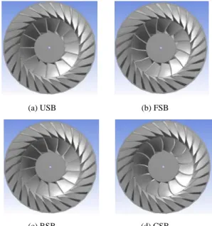
(a) USB (b) FSB
(c) BSB (d) CSB
Fig. 4 Front Views of Impellers
Figure 3 and Figure 4 show the contour line of the coordinate theta (circumference angular coordinate) on the blade meridional profile and front view of whole impeller. From Fig.3 it can be noticed that the coordinate theta is changed only in the front part of the blade while maintained unchanged in the rest of the blade.
Comparison of Impeller Performances The predicted overall performances of the swept impellers are compared with the performance of the unswept datum blade in Fig.5.
All calculations are performed at the nominal impeller design speed. The stagnation pressure ratios and the isentropic efficiencies are calculated using the total pressure and total temperatures at the exit plane of the impeller.
The strong effect of sweep on the impellers’ peak efficiency and pressure ratio can be seen in Fig.5.
The application of backward swept BSB improves the peak efficiency by about 0.9% compared to the unswept datum impeller while the efficiency of CSB was enhanced by 1%. The improvements, however, diminish for the near choking operation. The forward sweep FSB shows the opposite effect by reducing the performance over entire operating range.
a)
b)
Fig.5 Effects of Blade Sweep on Impeller Performance
No strong effect of the sweep on the machine’s mass flow capacity can be observed. Most of the change in the throat area occurs in the upper half of the span. At high mass flow rates where the main passage shock moves downstream, the choking mass flow rate is determined by the throat area of the splitter passages. The blade geometry remains the same in this region for all cases, limiting the effect of the blade sweep on the impeller’s flow capacity.
Effects of Blade Leading Edge Sweep on the Flow Structure
The effects of geometrical blade leading edge sweep on the detailed impeller flow structure are presented in this section. The aim is to relate the variation of the overall performance with the changes in the flow inside the passages. The flow field inside the unswept and the swept blades are compared at the same mass flow rates close to the peak efficiency.
Hence at the same flow coefficient, changes in the pressure rise capacity of the passages can be compared. Figure 6 shows contours of the relative Mach number at 85 percent of the span for the unswept and the swept blades.
a) USB b) FSB
c) BSB d) CSB
Fig. 6 Contours of Relative Mach number at 85 % of the Blade Span
The main passage shock waves can be observed on the suction surface of the blades. The passage shock occurs upstream of the leading edge of the main blade and turns perpendicular to the suction surface as it approaches the blade. From Fig.6 it can be noticed that the forward sweep increases a stronger main passage shock. Conversely, the application of the backward sweep weakens the shock. The lower strength of passage shock wave may reduce the interaction strength between shock and the suction surface boundary layer, resulting more uniform flow flied in the passage.
It is generally acknowledged that a more uniform impeller exit flow is beneficial for the diffuser performance in a centrifugal stage. Hence the effect on the impeller exit flow pattern should be addressed in any parametric investigation of the impeller geometry. Effects of the blade sweep on the flow non-uniformities are shown in Fig.7, by presenting the contour lines of the absolute Mach number at impeller exit. The figure demonstrated the flow at the exit of one complete passage consists of two splitter passages.
Fig.7 Contours of the Absolute Mach number at Impeller Exit
A lower level of non-uniformities in the second splitter passage compared to the first one is clear in the contours of CSB. The extent of the high momentum core in the second passages is reduced for the curve backward swept blade. This may reduce the jet/wake effect on the blade outlet and provide more uniform inlet condition for the diffuser.
Effects of Blade Leading Edge Sweep on the Structure Stress
The effects of blade leading edge sweep on the detailed impeller structure stress distribution are presented in this section. The stress of the unswept and the swept blades are compared at the same rotating speed and constraint condition.
Figure 8 shows the contour plot of the equivalence stress distribution on the suction side of the blade.
a) USB b) FSB
c) BSB d) CSB
Fig.8 Contour Plot of the Stress on the Blade
It can be found that the maximum stress of the blade is reduced obviously by 15% for the CSB blade as compared to the USB blade. Conversely, the application of the FSB enhances the maximum stress greatly.
The positions of maximum stress on unswept and swept blade are all at the middle part along the root of the blade. In addition, the geometry variations in the front part of the blade also change the stress distribution on blade surface. The stress distribution
of BSB blade is similar to USB and both of which have low stress area on the tip of leading edge, while CSB blade’s low stress area are concentrated along the leading edge. It can be noted that an obviously stress increasing at the root of FSB near the leading edge.
Fig.9 Stress Distribution along Blade Root Comparisons of the detailed stress value of the unswept and swept blade along the blade root are shown in Fig.9. From the leading to trailing on the root of the blade, the stress values of four blades are closer to each other over the whole curve length of the blade. The maximum stress position is at the middle part of the curve which is coincidence with the stress contour plot of the blade. All the stress near the leading edge keeps low value except FSB and forward swept blade causes high stress concentration at the root. The deformation of the blade consists of bending and twisting deformation and it also has great relation ship with the deformation of impeller hub at the same time.
Totally saying, the stress distribution along the rear part on the root of blade is affected little while great on the leading edge by sweeping in the front part of the blade.
Conclusions
The effects of the main blade leading edge sweep on the aerodynamic performance and structure stress of a transonic centrifugal impeller have been numerically investigated.
In general, application of backward sweep resulted in a higher efficiency, whilst efficiency is reduced for forward swept blades. The beneficial effects of backward sweep are due to the reduction of the blade loading in the tip region. The direct consequence is to reduce the strength of shock shock/boundary layer interactions in the passage, resulting in the superior performance of the backward swept blades.
Conversely the loading at the tip region is increased with forward sweep, giving rise to stronger loss inside the impeller.
On the other hand, the backward swept blade is beneficial for reducing the stress value and changing the stress distribution along the leading edge.
However, the stress distribution along the root is affected little by sweeping the front part of the blade.
Studies have shown that it is possible to control the stress distribution along the tip and root of the blade by slight adjustments to the sweep angle of the leading edge. These adjustments may be used to design the impeller with lower blade root stress distribution without aerodynamics performance penalty.
Acknowledgements
The authors are grateful for the financial support of the National Natural Science Foundation of China under grant No. 50725621. The authors also would like to thank Wang Zhiheng and Ma Yan for their help during the course of the design effort.
Reference
1) Koch C.C., Smith L.H. Jr. Loss Source and Magnitudes in Axial-Flow Compressor. ASME Paper 75-GT-6, 1975.
2) Hah, C., Puterbaugh, S.L. & Waidia, A.R.
Control of Shock Structure and Secondary Slow field inside Transonic Compressor Rotors through Aerodynamic Sweep. ASME Paper, 98-GT-561, 1998.
3) Palmer, D.L. & Waterman, W.F. Design and Development of an Advanced Two-stage Centrifugal Compressor. Transaction of ASME, Journal of turbo-machinery. 1995, Vol. 117, pp 205-212.
4) Rodgers, C. High Specific Speed, High Inducer Tip Mach Number Centrifugal compressor. ASME Paper, GT-2003-38949, 2003.
5) Krain, H., Hoffmann,B. Flow Study of a Redesign High Pressure Ratio Centrifugal Compressor. ISABE-2007-1223,2007
6) Hamid R. Hazby & Liping Xu. Effect of Leading Edge Sweep on Performance of a Transonic Centrifugal Impeller.
ISABE-2007-1225,2007
7) Kosuke ASHIHARA, Shijie GUO,Akira GOTO and Hidenobu OKMOTO. Optimization of Micro-turbine Aerodynamics Using CFD, Inverse Design and FEM Structure Analysis (1st report: compressor design). ASME Paper, GT-2004-53431,2004