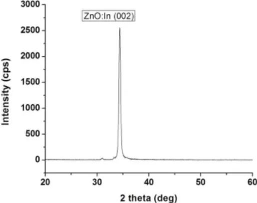
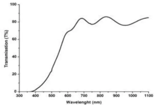
Fabrication and characterization of n-IZO / p-Si and p-ZnO:(In, N) / n-Si thin film hetero-junctions by dc magnetron sputtering
7
0
0
전체 글
(2)
(3)
(4)
(5)
(6)
(7)
수치

관련 문서
[r]
present everything to the students, but they should instead let students find a problem and solve it through various methods on their own to suit the STEAM class structure..
모든 사항 숙지 후, 동의하고 수강신청 진행... 연수지명번호 입력
전문기관에서 개발한 초등학교, 중학교, 고등학교 별 STEAM 프로그램 교사용 지도서 및 학생 활동지를
[r]
학술연구단체나 기술연구단체가 학술연구 또는 기술연구와 관련하여 공급하는 재화 또는 용역 (「산업교육진흥 및 산학연협력촉진에 관한 법률」에 따라
Fi g.7.Uni vari ate anal ysi s of 163 pati ents of gastri c adenocarci noma shows a si gni fi cantdi fference i n the overal lsurvi valaccordi ng to the Ets-1expressi on(p=0..
학교・유관기관・지역사회 협력
