Vol. 23, No. 2 (2013)
149
Detection of Delamination Crack for Polymer Matrix Composites with Carbon Fiber by Electric Potential Method
Soon-Gi Shin †
Department of Advanced Materials Engineering, College of Samcheok, Kangwon National University, Samcheok, Gangwon-do 245-711, Korea
(Received December 21, 2012 : Received in revised form February 13, 2013 : Accepted February 14, 2013)
Abstract
Delamination crack detection is very important for improving the structural reliability of laminated composite structures. This requires real-time delamination detection technologies. For composite laminates that are reinforced with carbon fiber, an electrical potential method uses carbon fiber for reinforcements and sensors at the same time. The use of carbon fiber for sensors does not need to consider the strength reduction of smart structures induced by imbedding sensors into the structures.With carbon fiber reinforced (CF/) epoxy matrix composites, it had been proved that the delamination crack was detected experimentally. In the present study, therefore, similar experiments were conducted to prove the applicability of the method for delamination crack detection of CF/polyetherethereketone matrix composite laminates. Mode I and mode II delamination tests with artificial cracks were conducted, and three point bending tests without artificial cracks were conducted. This study experimentally proves the applicability of the method for detection of delamination cracks. CF/polyetherethereketone material has strong electric resistance anisotropy. For CF/polyetherethereketone matrix composites, a carbon fiber network is constructed, and the network is broken by propagation of delamination cracks. This causes a change in the electric resistance of CF/
polyetherethereketone matrix composites. Using three point bending specimens, delamination cracks generated without artificial initial cracks is proved to be detectable using the electric potential method: This method successfully detected delamination cracks.
Key words
detection, electrical resistance, composites, carbon fiber, polyetherethereketone.1. Introduction
Laminated composite plates fabricated by stacking unidi- rectional plies have superior specific mechanical properties to that of the conventional metallic materials.
1)The lamin- ated composite plates, however, have a weak point at delamination resistance, and this causes delamination cracks by small impacts such as tool drops. Since the delami- nation cracks are usually invisible or difficult to find by naked eyes, the delamination causes low reliability for primary structures of laminated composites. In order to improve this low reliability, real time automatic detection of delamination cracks is required. Health monitoring sys- tem for detection of the delamination cracks is very desirable technology for actual laminated composite struc- tures. Embedding optical fiber sensors into laminated com- posites is one of the approaches for the detection of
delamination cracks
2-4)automatically. The approach, how- ever, brings reduction of strength or fatigue strength that is caused by embedding optical fiber sensors, and the approach is high cost because the optical fiber sensors are usually high costs. A new technology, therefore, is desired for the smart structures for detection of delamina- tion crack. An electric potential method is usually inves- tigated in detail for conventional metallic structures for detection of cracks or defects.
5)In the present study, the electric potential method was attempted for detection of delamination cracks. The electric potential method does not require high cost equipment. Since the method uses reinforcement carbon fiber as delamination detection sen- sors, this method does not cause strength or fatigue strength reduction.
Principle of electric potential method for carbon fiber reinforced polymer matrix composites(CF/PMC) as follows.
†
Corresponding author
E-Mail : ([email protected], Kangwon Nat'l Univ.)
© Materials Research Society of Korea, All rights reserved.
This is an Open-Access article distributed under the terms of the Creative Commons Attribution Non-Commercial License (http://creative-
commons.org/licenses/by-nc/3.0) which permits unrestricted non-commercial use, distribution, and reproduction in any medium, provided
theoriginal work is properly cited.
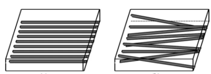
Carbon fiber has low electric resistance, and the polymer matrix for CF/PMC is usually insulation resistance. For ideal CF/PMC, electric resistance in fiber orientation is very low(almost zero), and the electric resistance of trans- verse orientation is ideally infinite. Carbon fiber in a unidi- rectional ply is, however, serpentine, and is not completely straight. The tangled carbon fiber in a ply makes a large carbon fiber network as shown in Fig. 1. The network has finite electric resistance even in the transverse orientation.
In the same way, the network causes finite electric re- sistance in the thickness orientation in a ply. The electric resistance in transverse direction is much lower than that of fiber orientation and thickness direction. This causes electric resistance anisotropy for CF/PMC. Though the fiber network structure in the thickness orientation almost equals to the structure in the transverse orientation, total electric resistance in the thickness orientation is larger than that of transverse orientation for laminated composites.
That is because there are many thin resin rich interlaminae in laminated composites. For ideal CF/PMC, electric resist- ance in thickness orientation is infinite due to the resin rich interlaminae. For actual CF/PMC, however, a carbon fiber reinforced polymer matrix ply is serpentine such as fiber in a ply. This curve of a ply yields finite electric re- sistance in the thickness direction even for thick laminated CF/PMC. When a delamination crack generates in the resin rich interlaminae, the crack breaks the fiber network bet- ween plies. The breakage of the network yields increase of electric resistance.
Author has already investigated the applicability of the electric potential method for measurements of delami- nation crack length for mode I and mode II tests.
6,7)In the previous study, CF/epoxy laminated composite plates were used to investigate applicability of the method experimentally. Double cantilever beam specimens and end notch flexure specimens were adopted to obtain relations between electric potential change and delamination crack length. Two electrodes were attached on the top of the specimen surface, which modelled detection of delami- nation cracks from inside of aircraft structures. By using electric resistance bridge circuits, the small electric re- sistance change was measured with small electric current.
The electric potential method was applied to the lamin- ated composite specimens that had multi-direction fiber
angles by Todoroki.
8)Mode I and mode II type delami- nation tests were conducted to obtain relations between electric resistance change and delamination crack length with specimens of three kinds of stacking sequences.
Specimens produced from two kinds of fabrication methods were also tested. The results showed that the delamination crack plane transition causes large change of electric resistance and that fabrication method has large effect on electric conductivity. Matrix of CF/poly- etherethereketone matrix composite is a kind of thermo- plastic materials, and the fabrication method of CF/poly- etherethereketone is largely different from that of CF/
epoxy matrix composites. Since the flow of polyether- ethereketone matrix at processing temperature is generally worse than that of epoxy. Electric resistance anisotropy is assumed to be largely different from CF/epoxy matrix composites. In the present study, therefore CF/polyether- ethereketone matrix composite laminates were adopted as material for testing. Mode I and mode II delamination tests were conducted. Relation between electric resistance change and delamination crack length were measured.
Practical delamination cracks, which grows from matrix crack, was attempted to be detected by using three point bending specimens without artificial initial defects.
2. Experimental Procedure
Material used in the present study is AS-4/polyether- ethereketone(Asahi Chemical Co.). Prepreg sheet APC- 2(Japan Carbon Co.) was used, and fabricated under the condition of 623 K × 0.4 Mpa × 1.5 hr. Three types of laminates were fabricated. Type A specimens have stacking sequence of [0]s, and have artificial defects at the edge of the specimens. The artificial defects were introduced by inserting film in the middle of the thickness. From the laminates, mode I and mode II delamination test speci- mens of length 200 mm, width 20 mm and thickness 2 mm were fabricated. Specimen configurations and jigs were shown in Fig. 2, respectively. For mode I specimens, Glass fiber reinforced epoxy matrix composite plates were adopted as insulator between jigs and CF/polyetherethere- ketone specimens. For mode II specimens, Teflon film Fig. 1. Carbon fibers in a ply of CF/PMC. (a) ideal and (b) practical.
Fig. 2. Specimen configurations and jigs. (a) Mode I specimen and
(b) Mode II specimen.
was used as insulator between jigs and CF/polyetherethere- ketone specimens.
Mode I and mode II delamination tests were conducted to obtain basic electric properties and to investigate ap- plicability of the electric potential method for CF/poly- etherethereketone composites. By using these specimens, relations between electric resistance change and delami- nation crack length was measured. Delamination crack length was directly measured with reading microscopes from the specimen side surface. Three point bending specimens were made from type B laminates of [0
4/90
4]s, and the specimens have no artificial defects. Similarly, the same configuration specimens were made from type C lamin- ates of [90
4/0
4]s, and have no artificial initial defects. Both types of specimens have length 60 mm, width 20 mm and thickness 2 mm. Specimen configurations is shown in Fig. 3. The three point bending tests were conducted to investigate applicability of the electric potential method for actual delamination cracks that do not generate from artificial defects. For the type B and C laminates, matrix cracks occur in a 90 degree ply first of all. The matrix cracks were stopped at the interlamina between 90 degree ply and 0 degree ply. The cracks are initiator of delami- nation cracks.
Electrodes were constructed on specimen surfaces as follows. A specimen surface was polished by the polishing paper. The polished side was washed with acetone. The polished side was polished again by using Al
2O
3powder.
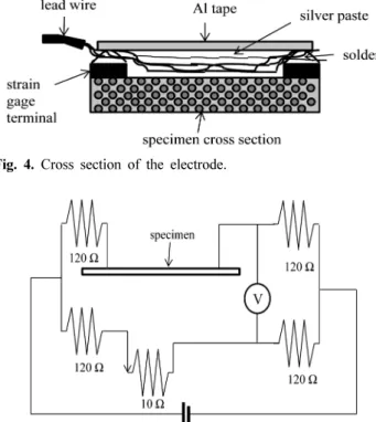
The polished side was cleaned with acetone. Silver paste was painted on surface. Strain gage terminals were attached with adhesive. Lead wire was soldered to the strain gage terminal. Lead wire was attached to specimen surface by using silver paste. The whole part of an electrode was covered with Al tape. Cross section of the electrode was shown in Fig. 4. Since electric resistance change due to delamination crack growth is very small for the specimen shown in Fig. 2 and Fig. 3, an electric resistance bridge circuit was used to measure the resistance change by small electric current as shown in Fig. 5. A direct current strain amplifier was used as bridge circuit electric power
source supplier and also as bridge circuit voltage amplifier.
For all the tests, MTS closed-loop material testing ma- chines(R&B Co.) were used. Tests were conducted under displacement control condition at cross head speed of 1 mm/min.
3. Results and Discussion
Measured relation between electric resistance change and delamination crack length of mode I was shown in Fig. 6. The ordinate is electric resistance change ratio nor- malized by initial electric resistance(R
o), and the abscissa is delamination crack length normalized by specimen length (L). For most of unidirectional CF/epoxy matrix compo- sites, the relation was linear. The relation of the unidi- rectional CF/polyetherethereketone is non-linear as shown in Fig. 6 in the shorter delamination region( ∆a/L ≤ 0.15).
Since there is resin rich region near the artificial initial defects due to fabrication process of CF/ polyetherethere- ketone matrix composites, electric resistance change near the initial defect is non-linear for a short crack.
For materials of isotropic electric resistance, the electric resistance(R) is defined R = ρ(l/s), where ρ is specific re- sistance, l is length and s is cross section area. For the region where delamination crack has propagated, the cross section area is half of the initial thickness. The electric resistance for the region where delamination crack has propagated is twice as large as that of initial thickness.
The total electric resistance(R
t) is calculated ρ(2a/s) + ρ{(L − a)/s}. Where a is crack length measured from the Fig. 3. Specimen configuration of three point bending test.
Fig. 4. Cross section of the electrode.
Fig. 5. Electric resistance bridge circuit.
electrodes, and L is distance between two of electrodes on the specimen surface. Initial electric resistance(R
o) is ρ(l/s). By using R
tand R
o, electric resistance change ratio( ∆R/R
o) can be obtained.
8,9)∆R/R
o= (R
t− R
o)/R
o= a/L (1) Therefore, the relation between electric resistance( ∆R/
R
o)and delamination crack(a/L) is direct proportion.
Since electric resistance of 0 degree plies is very low compared to resistance of other directions, it is most electric current flows near the specimen top surface for unidirectional laminates. This decreases the effect of the decrease of the cross section of electric flow pass. There- fore, the measured relation is not direct proportion, and the inclination is lower than 1. The low inclination implies that the CF/polyetherethereketone has strong ani- sotropy in electric resistance. Measured relation between
electric resistance change and delamination crack length of mode II was shown in Fig. 7. For mode II tests, delamination crack surfaces keep contact with each other due to the loading. This implies that fiber network is completely broken by the delamination crack growth even for mode II loading, and the network is not repaired by unloading.
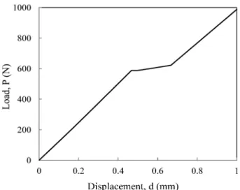
10)Measured relation between electric resistance change and loading displacement for a type B three-point-bending specimen is shown in Fig. 8 and Fig.
9. In these figures, load-displacement relation is also shown. At the point approximately d = 0.47 mm, a de- lamination crack generated just after the initiation of a matrix crack. At the point, there is a kink point in the load-displacement relation. The change is, however, small.
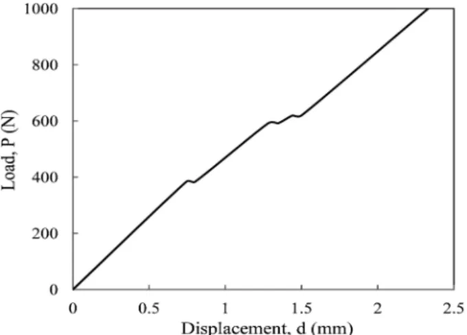
Measured relation between electric resistance change and loading displacement for a type C three point bending specimen is shown in Fig. 10 and Fig. 11. The ordinate and abscissa are the same as those of Fig. 8. At the point approximately d = 0.75 mm, there was a first matrix crack- Fig. 6. Relation between electric resistance change and delamination
crack length of mode I test.
Fig. 7. Relation between electric resistance change and delamination crack length of mode II test.
Fig. 8. Relation between load and displacement of three point bend- ing test of type B.
Fig. 9. Relation between resistance change and displacement of three
point bending test of type B.
ing at the opposite surface to the center-loading point. At the point approximately d = 1.29 mm, a delamination crack generated near the matrix crack, and there was large change of electric resistance at the point. We can con- clude that delamination cracks generate without artificial defects can be detected by using the electric potential method with the electric resistance bridge circuit. The electric resistance change due to matrix cracking is very small in each case. This is due to the strong electric anisotropy.
11-13)Since the electric resistance of 90 degree ply is much higher than that of 0 degree ply, only small amount of electric current flows in 90 degree plies. The matrix crack in 90 degree plies does not cause large change of electric current. Therefore, the electric potential method is appropriate for detecting delamination cracks.
4. Conclusion
The electric potential method with electric resistance bridge circuits was applied to detect delamination cracks of CF/polyetherethereketone composite laminates. The applicability of the method for detection of delamination crack was experimentally proved in the present research.
CF/polyetherethereketone material has strong electric re- sistance anisotropy. For CF/ polyetherethereketone matrix composites, the carbon fiber network is constructed, and the network is broken by propagation of delamination cracks. This causes electric resistance change for CF/
polyetherethereketone matrix composites. By using three points bending specimens, delamination cracks generate without artificial initial cracks is proved to be detectable using the electric potential method. Since the electric resistance change due to matrix cracks is much smaller than that due to delamination crack propagation, delami- nation crack generation can be distinguished from matrix crack generations.
References
1. N. Shinya, Frontier of Next-Generation Structural Ma- terials-Impact on Society and Industry, p.97, cmcbooks Co., Tokyo, Japan (2008).
2. A. D. Kersey, in Proceedings of the First World Con- ference on Structural Control(Los Angeles, CA, August 1994), Plenary 3.
3. S. F. Masri, M. S. Agbabian, A. M. Abdel-Ghaffar, M.
Higazy, R. O. Claus and M. J. de Vries, J. Eng. Mech., 120, 1696 (1994).
4. C. I. Merzbacher, A. D. Kersey and E. J. Friebele, Smart Mater. Struct., 5, 196 (1996).
5. C. Ishida, Handbook of Electronic Materials, p. 769, ed.
K. Z. Asakura, Asakura Shoden, Tokyo, Japan (2006).
6. S. G. Shin, Kor. J. Mater. Res., 20, 271(2010) (in Korean).
7. Y. Okuhara, S. G. Shin, H. Matsubara, H. Yanagida and N. Takeda, Proc. SPIE, 4328, 314 (2001). doi:10.1117/
12.435534.
8. A. Todoroki, H. Kobayashi and K. Matsuura, J. Jpn. Soc.
Compos. Mater., 21, 89 (1995) (in Japanese).
9. S. G. Shin, Electron. Mater. Lett., 6, 65 (2010).
10. S. G. Shin, Kor. J. Met. Mater., 48, 867 (2010).
11. S. G. Shin and I. K. Kwon, Electron. Mater. Lett., 7, 249 (2011).
12. S. G. Shin, Kor. J. Mater. Res., 21(4), 196 (2011) (in Korean).
13. S. G. Shin, Kor. J. Mater. Res., 21(9), 477 (2011) (in Korean).