*학생회원, 공주대학교/정보통신공학과 & Beihua University, Jilin, China
**정회원(교신저자), 공주대학교/전기전자제어공학부
***학생회원, 충남대학교/전자공학과
****정회원, 충남대학교/전자공학과
*****
정회원, 서울산업대학교/전자공학과 접수일자 2010.05.31 수정일자 2010.06.18
논문 2010-3-11
UWB 센서에 의한 광대역 무선 시스템의 간섭 영향 분석
Analysis on the Impact of UWB Sensor on Broadband Wireless Communication System
정연명*, 이일규**, 이용우***, 오승엽****, 차재상*****
Yan-Ming Cheng, Il-Kyoo Lee, Yong-Woo Lee, Seung-Hyeub Oh, Jae-Sang Cha
요 약 본 논문은 간섭원으로써 4.5 GHz를 사용하는 UWB 센서가 동대역을 사용하는 피간섭원 광대역 무선 시스 템에 미치는 간섭을 분석하였다. 분석방법으로는 Minimum Coupling Loss(MCL)와 Spectrum Engineering Analysis Monte Carlo Advanced Tool(SEAMCAT)을 사용하였으며 그 결과는 다음과 같다. 양립성 확보를 위해서 UWB 센서와 광대역 무선 시스템의 이동국 사이에는 1.2 m 이상의 보호 이격거리가 요구되었고 다수의 UWB 센서가 존재하는 경 우에는 간섭 확률 5 % 이하를 만족하기 위해 UWB 수신기 PSD는 -68.5 dBm/MHz 이하로 요구되었다.
Abstrac
t This paper presents the impacts of Ultra Wide-Band(UWB) sensor using frequency of 4.5 GHz on Broadband Wireless communication system which uses frequency of 4.5 GHz. The Minimum Coupling Loss (MCL) method and Spectrum Engineering Advanced Monte Carlo Analysis Tool (SEAMCAT) is used to evaluate the interference effects of UWB sensor on Broadband Wireless communication system, respectively. The minimum protection distance between single UWB sensor and mobile station of Broadband Wireless communication system should be more than 1.2 m to guarantee the co-existence. In case of multiple UWB sensors, UWB transmitting PSD of around –68.5 dBm/MHz below should be required to guarantee interference probability of 5% below for mobile station of Broadband Wireless communication system.Key Words :
UWB sensor, Broadband Wireless communication system, Interference probability, Guard bandⅠ. Introduction
The importance of Ultra Wide-band(UWB) technology has been increased with the advent of communication services including low-cost, high speed and wireless network in these days. In addition, as the
frequency resources become limit, the technology has been highly attracted in order to share the frequencies between UWB system and other existing services such as mobile communication, satellite communication and broadcasting system.
As the UWB spreads from DC to several GHz, it is
appropriate for short-range communication networks
requiring high rate and large capacity of data
transmission. The UWB technology has been developed
mainly for the distance measurement, communications
devices for the military purpose and object
measurement in basement
[1]. The Federal
Communications Commission (FCC) defined the UWB system as 20 % above Fractional Bandwidth of center frequency or the system with 500 MHz above RF bandwidth
[2]. In the past, the impulse method has been suggested to get wide-band frequency characteristics as an implementation method. Although Multiband Orthogonal Frequency Division Multiplexing (MB-OFDM) and Direct Sequency-CDMA(DS- CDMA) have been discussed actively in IEEE. Because they have advantages of implementation feasibility and flexible frequency bandwidth
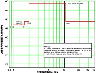
[3], and FCC has provided spectrum mask illustrated in Figure 1 for UWB Surveillance systems, but the potential interference due to the very large bandwidth occupied by the UWB signal have been reevaluated for the successful operation of the existing systems. The impacts for interference of UWB systems to the existing communication systems have to be considered in the worst case.
1 5 10 20 30 40
FREQUENCY, GHz 0.96 1.61
1.99 10.6
RNSS BAND
-75 -70 -65 -60 -55 -50 -45 -40
UWB EIRP DENSITY, dBm/MHz
0.8 1 5 10 20 30 40
FREQUENCY, GHz 0.96 1.61
1.99 10.6
RNSS BAND
-75 -70 -65 -60 -55 -50 -45 -40
UWB EIRP DENSITY, dBm/MHz
-75 -70 -65 -60 -55 -50 -45 -40
UWB EIRP DENSITY, dBm/MHz
-41.3 dBm/MHz -41.3 dBm/MHz
0.8
NOTES:
1. UWB EMISSION L IMITS ABOVE 960 MHz ARE BASED ON EIRP MEASUREMENTS USING AN RMS DETECTOR WITH 1 MHz RESOL UTION BANDWIDTH.
NOTES:
1. UWB EMISSION L IMITS ABOVE 960 MHz ARE BASED ON EIRP MEASUREMENTS USING AN RMS DETECTOR WITH 1 MHz RESOL UTION BANDWIDTH.
2. AT OR BELOW 960 MHz TABLE 2 APPL IES
1 5 10 20 30 40
FREQUENCY, GHz 0.96 1.61
1.99 10.6
RNSS BAND
-75 -70 -65 -60 -55 -50 -45 -40
UWB EIRP DENSITY, dBm/MHz
0.8 1 5 10 20 30 40
FREQUENCY, GHz 0.96 1.61
1.99 10.6
RNSS BAND
-75 -70 -65 -60 -55 -50 -45 -40
UWB EIRP DENSITY, dBm/MHz
-75 -70 -65 -60 -55 -50 -45 -40
UWB EIRP DENSITY, dBm/MHz
-41.3 dBm/MHz -41.3 dBm/MHz -41.3 dBm/MHz -41.3 dBm/MHz
0.8
NOTES:
1. UWB EMISSION L IMITS ABOVE 960 MHz ARE BASED ON EIRP MEASUREMENTS USING AN RMS DETECTOR WITH 1 MHz RESOL UTION BANDWIDTH.
NOTES:
1. UWB EMISSION L IMITS ABOVE 960 MHz ARE BASED ON EIRP MEASUREMENTS USING AN RMS DETECTOR WITH 1 MHz RESOL UTION BANDWIDTH.
2. AT OR BELOW 960 MHz TABLE 2 APPL IES NOTES:
1. UWB EMISSION L IMITS ABOVE 960 MHz ARE BASED ON EIRP MEASUREMENTS USING AN RMS DETECTOR WITH 1 MHz RESOL UTION BANDWIDTH.
NOTES:
1. UWB EMISSION L IMITS ABOVE 960 MHz ARE BASED ON EIRP MEASUREMENTS USING AN RMS DETECTOR WITH 1 MHz RESOL UTION BANDWIDTH.
2. AT OR BELOW 960 MHz TABLE 2 APPL IES
그림 1. UWB 감시 시스템의 방사 마스크
Fig. 1. UWB Surveillance systems emission mask
This paper analyzes particularly the impacts of UWB sensor system of Samsung Company using frequency of 4.5 GHz on Broadband Wireless communication system which uses frequency of 4.5 GHz in outdoor, The Minimum Coupling Loss (MCL) and SEAMCAT are used as interference analysis methods to evaluate the interference effects of UWB sensor system on Broadband Wireless communication
system
[4],[5].
The analysis results show the minimum protection distance between UWB system and Broadband Wireless communication system as well as the allowable transmitting power spectral density of UWB sensor system for the compatibility.
Ⅱ. Interference analysis of the impact of single UWB sensor on mobile of Broadband Wireless communication system in Outdoor environment
The impact of single UWB sensor on mobile station of Broadband Wireless communication system is analyzed in terms of MCL method. The system parameters for MCL method and analysis scenario for worst case are considered. The minimum protection distance between interferer and victim system is obtained.
The scenario for the interference analysis is established as follows. Service environment: Outdoor environment. Interferer: single UWB sensor. Victim system: mobile station of Broadband Wireless communication system. UWB sensor transmitting power spectral density(PSD): -63 dBm/[email protected] GHz provided by Samsung Company in Outdoor. In Bands:
3.1 ∼ 10.6 GHz, Antenna characteristics: omni directional. Reference Distance: 36 cm or 1m. Reference Bandwidth: 1 MHz.
The specifications of Broadband Wireless communication system are defined as follows.
Operating frequency: 4500 MHz. Channel bandwidth: 10 MHz. Noise Figure: 8 dB. Noise Floor: -96 dBm.
Antenna characteristic: Omni directional antenna. Path loss model: free space path loss.
When the protection criteria which is the ratio of
Interference over Noise Floor (I/N) was defined as -6
dB by considering worst case scenario, the allowable
maximum UWB PSD and the minimum protection
distance is analyzed. The analysis results using MCL
method are summarized in Table 1.
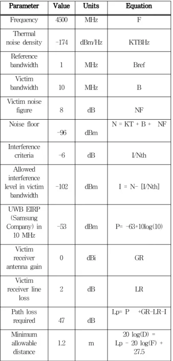
표 1. MCL과 시스템 파라미터를 이용한 간섭 분석 결과 요약 Table 1. The summary of interference analysis
results using system parameters and MCL method
Parameter Value Units Equation
Frequency 4500 MHz F
Thermal
noise density -174 dBm/Hz KTBHz Reference
bandwidth 1 MHz Bref
Victim
bandwidth 10 MHz B
Victim noise
figure 8 dB NF
Noise floor
-96 dBm N = KT + B + NF Interference
criteria -6 dB I/Nth
Allowed interference level in victim
bandwidth -102 dBm I = N- [I/Nth]
UWB EIRP (Samsung Company) in
10 MHz -53 dBm P= -63+10log(10) Victim
receiver
antenna gain 0 dBi GR
Victim receiver line
loss
2 dB LR
Path loss
required 47 dB Lp= P +GR-LR-I Minimum
allowable
distance 1.2 m 20 log(D) = Lp - 20 log(F) +
27.5
Based on Table 1, when 0.36 m is chosen as reference distance, the maximum allowable UWB PSD
= -73.3 dBm/MHz.
Ⅲ. The analysis of the impact of multiple UWB sensors on mobile station of Broadband Wireless communication system in Outdoor environment
The SEAMCAT is used for the analysis of the impact of multiple UWB sensors on mobile station Broadband Wireless communication system in Outdoor environment. System parameters and scenario are defined for the SEAMCAT analysis. The maximum UWB transmitting PSD is considered so as to keep minimum interference probability so much as no occurring in mobile station Broadband Wireless communication system.
The analysis scenario is assumed in Figure 2.
Service environment: Outdoor. Interfering system:
UWB sensor system of Samsung Company. Interfering transmitter (It) is UWB sensor. UWB sensor transmitting PSD: - 63 dBm/[email protected] GHz provided by Samsung Company in Outdoor. The sensing distance is within 40 m of UWB , the space of fence pillar is 4 m, the fixing height on fence pillar is 2.2 m.
the beam width: horizontal is 150°, perpendicular is 35°, the density of transmitters/km
2is 25.
그림 2. 다수의 UWB 센서와 광대역 무선 통신 시스템 Fig. 2. Multiple UWB sensors and Broadband
Wireless communication system
Interfering system: We can limit UWB PSD = -63
dBm/MHz on in band of 4.2 ∼ 4.8 GHz depending on
the transmitting power of UWB sensor of Samsung
Company, however the UWB PSD limit on out of band refers to emission mask for UWB surveillance system that is provided by FCC. Figure 3 displays proposal emission mask for UWB sensor system in Korea.
Therefore, according to Figure 3, UWB emission mask is summarized in Table 3 and obtained as Figure 4 in SEAMCAT for interference analysis. Reference Bandwidth: 1 MHz. Main parameters of UWB sensor system of Samsung Company are summarized in table 2.
Victim system: Broadband Wireless communication system, Victim receiver (Vr) is the Mobile station (MS) of Broadband Wireless communication system, Wanted transmitter (Wt) is the Base station (BS) of Broadband Wireless communication system. Parameters for Broadband Wireless communication system are as follows: Operating frequency: 4500 MHz. channel Bandwidth: 10 MHz. Noise Figure: 8 dB. Noise Floor:
-96 dBm. Antenna height: 15 m for base station and 1.5 m for mobile station. Propagation model: Free space (considering the worst scenario). Main parameters of Broadband Wireless communication system are summarized in table 4.
그림 3. 한국의 UWB 센서를 위한 방사 마스크
Fig. 3. Proposal emission mask for UWB sensor system in Korea
표 2. 삼성 UWB 센서의 주요 파라미터
Table 2. Main parameters of UWB sensor system of Samsung Company
Parameter Value Units
Frequency 4500 MHz
UWB EIRP
(Samsung Company) -63 dBm/MHz Transceiver Antenna
Height 2.2 m
Antenna Gain 11 dBi
Sensing distance 40 m
Density of transmitters
/km2 25
Probability of transmission 1 It->Vr propagation model Free space
(considering the worst case)
표 3. 심켓에서의 UWB 센서 불요방사 마스크
Table 3. Unwanted mask for UWB sensor system in SEAMCAT
Frequency
offset(MHz) -63 dBm
UWB Power Attenuation in dBc in SEAMCAT
216-960 -40 23
960-1610 -53.3 9.7
1610-1990 -51.3 11.7
1990-4200 -41.3 21.7
4200-4800 -63 0
4800-10600 -41.3 21.7
>10600 -51.3 11.7
그림 4. UWB의 불요 방사 마스크
Fig. 4. Unwanted emissions mask for UWB
표 4. 광대역 무선 통신 시스템의 주요 파라미터
Table 4. Main parameters of Broadband Wireless communication system
Parameter Value Units Equation
Frequency 4500 MHz F
Thermal noise
density -174 dBm/Hz KT
Reference
bandwidth 1 MHz Bref
Victim bandwidth 10 MHz B
Victim noise figure 8 dB NF Interference criteria -6 dB I/Nth
Noise floor -96 dBm N=KT + B + NF SNR
(QPSK 1/2) 9.4 dB SNR
Victim receiver
(Vr)Sensitivity -86.6 dBm RS=KT+B +NF+SNR Victim receiver
antenna gain 0 dBi GR
Victim receiver line
loss 2 dB LR
Wanted transmitter
(Wt) power 30 dBm PWt
Wanted transmitter
gain 10 dBi GT
Path loss required 124.6 dB Lp=PWt+GR +GT-LR-RS Wt->Vr Coverage
radius 9 km 20lg(D)=LP
-20lg(F)+27.5 Base station height 15 m
Mobile station
height 1.5 m
Wt->Vr
propagation model Free space
Based on parameters of systems, Scenario is set up in SEAMCAT, and interference probability can be obtained through simulating in the SEAMCAT. The analysis results of the impact of multiple UWB sensors on mobile station of Broadband Wireless communication system are as following:
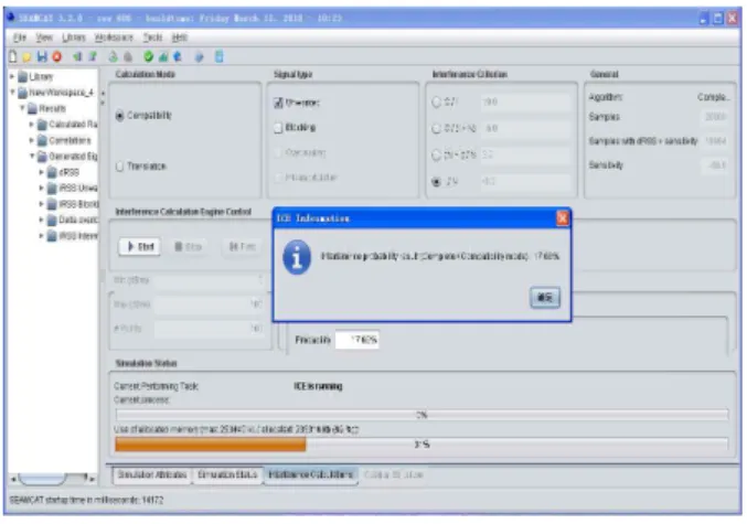
Calculation mode: Compatibility. Signal Type:
Unwanted. Interference criterion: I/N. Algorithm:
Quick. Samples: 20000, Density of transmitters/km
2=25, see Figure 5.
그림 5. UWB PSD = -63 dBm/MHz일때의 간섭 확률 Fig. 5. Interference probability when UWB PSD =
-63 dBm/MHz
Calculation mode: Translation, Signal Type:
Unwanted, Interference criterion: I/N. Algorithm:
Quick, Samples: 20000, Interference probability vs transmitter power supplied, Density of transmitters/km
2=25. The result is illustrated in Figure 6.
그림 6. 간섭 확률 대 UWB 송신 파워
Fig. 6. Interference probability vs UWB transmitter power supplied
Under condition of density of transmitters/km
2=25, from Figure 5, interference probability is 17.66 %, when UWB PSD = -63 dBm/MHz; from Figure 6, if interference probability of 0.5 % below is acceptable, UWB PSD should be -68.5 dBm/MHz below.
Figure 5, 6 show that It has different scenario comparing with chapter Ⅱ. Because chapter Ⅱ is single case which has only one interferer. But, chapter
Ⅲ is Multiple case which has 25 interferer. So, we
analyze to use SEAMCAT in chapter Ⅲ. Finally, we get Interference probability according to interference transmitting power. Also, Figure 5 is in Compatibility mode and Figure 6 is in Translation mode.
Ⅳ. Conclusion
The impact of single and multiple UWB sensors on mobile station of Broadband Wireless communication system have been analyzed through MCL method and SEAMCAT. In the case of Outdoor environment, the minimum protection distance between UWB interferer and mobile station of Broadband Wireless communication system and the allowable maximum UWB transmitting PSD are defined to meet I/N of –6 dB. The interference effect of multiple UWB sensors on mobile station of Broadband Wireless communication system is analyzed through SEAMCAT simulation to reduce or avoid occurring of interference probability in mobile station of Broadband Wireless communication system.
As a result, when I/N of –6 dB is chosen as protection criteria for the case of single UWB sensor, the required minimum protection distance between UWB interferer and mobile station of Broadband Wireless communication system should be more than1.2 m. When 0.36 m is chosen as reference distance between UWB interferer and mobile station of Broadband Wireless communication system, the maximum allowable UWB PSD = -73.3 dBm/MHz. In case of impact of multiple UWB sensors on mobile station of Broadband Wireless communication system, UWB PSD of -68.5 dBm/MHz below is required to guarantee interference probability of 5% below.
References
[1] Frank H. Sanders, Bradley J. Ramsey, Vincent S.
Lawrence, Broadband Spectrum Survey at Los
Angeles, California, NTIA Report 97-336, May 1997.
[2] FCC 02-48 First Report and Order(R&O), Revision of Part 15 of the Commission’s Rules Regarding Ultra-Wideband Transmission Systems: FCC, Feb. 2002.
[3] M. Ghavami, L.B. Michael and R. Kohno, Ultra Wideband Signals and Systems in Communication Engineering, John Wiely & Sons, 2004.
[4] Ultra-wideband, Report of the Fifth Meeting of ITU-R Task Group 1/8, San Diego, 18-27 May 2005.
[5] European Radiocommunications Office, SEAMCAT
Software Version 2.1 User Manual, 23 February
2004.
저자 소개 정 연 명(준회원)
∙2000:Jilin Institute of Technology Electric Engineering(공학사)
∙2007:공주대학교 대학원 정보통신공 학과(공학석사)
∙2008~현재:공주대학교 대학원 정보통 신공학과(공학박사과정)
<주관심분야 : UWB 통신, 전파 간섭>
이 일 규(정회원)
∙1994:충남대학교 대학원 전자공학과 (공학석사)
∙2003:충남대학교 대학원 전자공학과 (공학박사)
∙1997~2004:ETRI 선임연구원
∙2004~현재:공주대학교 전기전자제어 공학부 부교수
<주관심분야 : RFID/USN 기술, 이동무선통신, 안테나 및 전 파전파, 통방융합기술, 전파 간섭>
이 용 우(준회원)
∙1990:충남대학교 전자공학과(공학사)
∙1992:충남대학교 대학원 전자공학과 (공학석사)
∙1999~현재:충남대학교 대학원 전자공 학과(공학박사과정)
<주관심분야 : UWB 통신, 전파 간섭>
오 승 엽(정회원)
∙1971:연세대학교 전자공학과(공학사)
∙1973:연세대학교 전자공학과(공학석 사)
∙1982:연세대학교 전자공학과(공학박 사)
∙1980~1981:Tohoku University, Japan 재직
∙1985~1986: Pennsylvania State University, USA 초빙연구원 근무
∙1984~현재:충남대학교 전자공학과 교수, KICS, KIEES 그리 고 IEEE 정회원
<주관심분야 : 안테나 및 디지털 통신, RF Sub-System 분야 설계 등>
차 재 상(정회원)
∙2000:일본 東北대학교 전자공학과 (공학박사)
∙2002:ETRI 이동통신연구소 무선 전 송기술팀 선임연구원
∙2008:미국 플로리다 대학교 방문교 수
∙2005~현재:서울산업대학교 매체공학 과 교수
<주관심분야 : 디지털 방송전송기술, Cognitive Radio, 홈네트 워크 무선통신기술, UWB, 4세대 이동통신기술>