Matching Element Sensitivity Analysis for the
Operation of a Dual-band Power Amplifier with CRLH Transmission Lines
Byeonguk Lee*, Changwook Kim*, Youngcheol Park*★
Abstract
In this paper, we analyzed the sensitivity of matching elements for the dual-band operation of a power amplifier with composite right/left-handed (CRLH) transmission lines. Metamaterial theory enables CRLH transmission to support arbitrary impedance matching at dual frequencies. In general, at sub-GHz range, the CRLH matching networks are commonly implemented with lumped elements, which are prone to manufacturing distribution. In order to reduce the effect from the distribution of element values in design, we suggest a method to analyze the sensitivity of matching elements from the performance aspect of power amplifiers. Based on the analysis, a 40dBm dual-band power amplifier operating at 0.7GHz and 1.5GHz is designed.
Key words: PAPR, Power Amplifier, Efficiency, Envelope Tracking, Supply Modulator
* Dept. of Electronics Engineering, Hankuk University of Foreign Studies
★ Corresponding author
E-mail:[email protected], Tel:+82-31-330-4523
※ Acknowledgment
This research was supported by Hankuk University of Foreign Studies Research Fund, and Basic Science Research Program through the National Research Foundation of Korea(NRF) funded by the Ministry of Education (2017R1D1A1B03032874).
Manuscript received Dec. 7, 2018; revised Dec. 22, 2018; accepted Dec. 24, 2018
This is an Open-Access article distributed under the terms of the Creative Commons Attribution Non-Commercial License (http://creativecommons.org/licenses/by-nc/3.0) which permits unrestricted non-commercial use, distribution, and reproduction in any medium, provided the original work is properly cited
Ⅰ. Introduction
As the demand for wireless devices supporting multiple frequency bands in small packages is increasing, a lot of effort have been focused on multi-frequency technology and package minimization [1], [2]. As such, power amplifiers to support multiple bands are widely adopted, and dual-band operation is an important issue in terms of the miniaturization and the usage of a device [1]. In this regard, based on the CRLH transmission-line theory, arbitrary impedance matching at dual frequencies is a feasible solution [3]. However, when CRLH transmission line (TL) is implemented
with lumped elements, its performance may degrade significantly by inaccurate component values from manufacturing distribution [4]. For this reason, the distribution of lumped element values should be taken into account from the design process.
Therefore, we propose a method to analyze the sensitivity and identify the most critical component in CRLH TL networks and to find out the optimal values for the operation of the dual-band PA.
The matching network was designed for a 10W dual-band PA that supports dual frequencies (0.7GHz for the public safety operation and 1.5GHz for the satellite communication).
165
Ⅱ. Composite Right/Left Handed Transmission Line
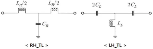
CRLH transmission line is an artificial structure showing pseudo-metamaterial characteristic with the conventional passive components. The Right- handed (RH) transmission line (TL) is composed of a shunt capacitance and series inductances, and it has a characteristic of low-pass frequency response. On the other hand, the Left-handed (LH) transmission line is composed of shunt inductors and series capacitors, showing high pass frequency response [5]. Fig. 1 shows the equivalent circuit of RH and LH transmission lines with lumped elements [6], [7].
In fact, it is quite difficult to implement LH TLs because of the parasitic capacitance in the LH TL within the series inductor, , which is a parasitic component due to the current flow. Also, during the inductor implementation of LH TL, the shunt capacitor introduces a parasitic component between the micro-stripline and the ground plate.
Fig. 1. Equivalent circuit of RH_TL and LH_TL.
At low frequencies, CRLH TL operates as an LH TL because the immittances (impedance and admittance) of and are negligible. At higher frequencies, CRLH TL operates as an RH TL because this time immittances of and
are negligible. Consequently, the CRLH TL has a bandpass characteristic [5]. Fig. 2 shows the equivalent circuit of the CRLH TL by using lumped elements and frequency response of the CRLH TL [7], [8].
Dual band matching can be realized from the characteristic of the CRLH TL, assuming that
the load impedance is defined as + =1/
( ) at . The first step is to transform
into with the feeding transmission line of and the phase shift, Φ as shown in Fig. 3. The impedance and the phase shift, Φ , Φ at the input of the feeding line can be calculated as follows [6]:
tanΦ
tanΦ
(1)
tanΦ
tan Φ tan Φ ,
(2)
Φ tan
±
,for ≠ (3)
tan
(4)
Similarly, for the design at f, two more phase shifts are calculated to match to 50 ohm [6].
When, the CRLH TL are built with the N repetition of the unit cell, the final components can be found as follows [6]:
ω ωω
Φωω Φ
(5)
ω ωω
Φωω Φ
(6)
ωΦ Φωω
ωω
(7)
ωΦ Φωω
ωω
(8)
Fig. 2. Equivalent circuit of CRLH TL and its frequency response.
Error rate 20%, Sensitivity(dBm/pF, dBm/nH)
0.7GHz 1.5GHz
Series CRLH TL branch
= 7nH 0.071 1.110
= 7nH 0.009 0.494
= 7.5pF 0.124 0.221
= 7.5pF 0.003 0.117
= 9nH 0.161 0.113
= 4pF 0.178 1.714
Fig. 3. Matching with the series-shunt stub tuning method.
Ⅲ. Sensitivity Analysis and Design
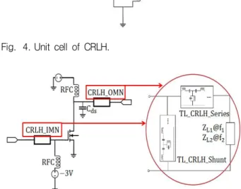
In this section, the sensitivity to PA performance from the variation of component values in the output matching network was analyzed by assuming 20% distribution from the mean value of each element. Fig. 4. shows the unit cell of a CRLH TL, where this unit cell is connected in series or shunt to compose matching networks. Fig. 5.
shows the schematic of the designed power amplifier based on CRLH TLs, which is composed of two unit cells for each series- and shunt- TL connection. At the first hand, a dualband PA was designed with ideal component values to operate at 0.7GHz and 1.5GHz for 40dBm output power.
Then, the variation of the output power of the PA at the desired frequencies was simulated with the distribution of component values in CRLH unit cells. Consequently, the sensitivity of the power to each component was analyzed, from which Table1 shows the effect of critical components in the output matching network (OMN). From the Table, series is identified as the most critical element in terms of the sensitivity of the output power. Then PAE and
are analyzed over the variation of the series
. Fig. 6. and Fig. 7. show PAE and over the variation of the series . In Fig. 6., it is shown that the series makes minimum sensitivity around the value of 3.6pF from the perspective of the output power. However, regarding the PAE, 4.2pF is found to be the optimal value. So, the can be chosen to have
3.9pF as a trade-off between the efficiency and the output power. In a similar manner, the second analysis was done on the effect of the series , and contours of performance metrics are found to get the optimal values of and
. While the shunt is the most sensitive at 0.7GHz, it is so dominant at the frequency that there is no need for the optimization with other component values. As well, at 1.5GHz, the aforementioned first two components do the most job.
Fig. 4. Unit cell of CRLH.
Fig. 5. Schematic of the designed power amplifier based on CRLH.
Table. 1. Sensitivity of elements in OMN composed of CRLH over the distribution of ±20% around the desired values.
Shunt CRLH TL branch
= 2nH 0.002 0.154
= 2nH 0.000 0.002
= 1pF 0.305 1.417
= 1pF 0.014 0.028
= 8nH 0.010 0.001
= 10pF 0.012 0.013
Fig. 6.Pout for variance of the series CR.
Fig. 7. PAE for variance of the series CR.
Fig. 8 and Fig. 9 show PAE and contour for the variance of the series and at 0.7GHz and 1.5GHz. From the contour, the value of can be chosen based on the value of
. The optimal point was chosen from the slope of the contour surface, with the given value of 3.9pF. As a result, and
are found as the optimal values for PAE and at the target frequencies.
Fig. 10, Fig. 11 and Table 2 show the performance of the designed PA.
Fig. 8. PAE and Pout contour for variance of the series CR and LR at the 0.7GHz.
Fig. 9. PAE and Pout contour for variance of the series CR and LR at the 1.5GHz.
Fig. 10. PAE and Pout over the input power.
Fig. 11. Small signal result of the designed PA.
Table. 2. Specification of the designed circuit.
0.7GHz 1.5GHz
PAE 69.27% 76.08%
Pout 40.03 dBm 40.77 dBm
S -13.94 dB -11.57 dB
S 27.71 dB 21.86 dB
Ⅳ. Conclusion
This paper suggests a design approach for a dualband PA based on CRLH transmission lines.
With the identification of the critical elements from its manufacturing distribution, we chose the optimal value of identified element with its given variation. The optimal values are used to design a 10W, dualband class-J PA. The designed PA showed outstanding performance of 76% and 69%, for the 40dBm output. This approach enables us to establish a process to mitigate the performance degradation from the manufacturing variation in component values, as well as to control the material cost with the given performance specification for a cost-effective product.
References
[1] S. Li, B. H. Tang, Y. A. Liu, S. L. Li, C. P.
Yu, and Y. L. Wu, “Miniaturized Dual-Band Matching Technique based on Coupled_Line Transformer for Dual-Band Power Amplifer
Design,” Progress In Electromagnetics Research, vol.131, pp.195-210, 2012. DOI:10.2528/PIER12072004 [2] Y. Park, H. Yoon, “Fast Characterization of Frequency Response in High-Speed Signal Generators with Frequency-Interleaving Technique,”
Accepted for the publication in MEASUREMENT, 2017. DOI:10.1016/j.measurement.2017.03.039 [3] Tatsuo Itoh, Christophe Caloz, Electromagnetic Metamaterials, John Wiley & Sons Inc., 2005.
[4] Y. C. Park and H. Y. Yoon, “Analysis on the Propagated Uncertainty of Output Power of Class-F Power Amplifiers from DC Biasing and Its Optimization,” JEES, vol.25, no.2, pp.183-188, 2014.
[5] I. Hsiang. Lin, Marc. DeVincentis, Christophe, Caloz, Tatsuo. Itoh, “Arbitrary Dual-Band Components Using Composite,” IEEE Trans. on Microwave Theory and Techniques, vol.52, no.4, 2004.
DOI:10.1109/TMTT.2004.825747
[6] Y. C. Park and H. C. Ku, “Design and Analysis of dual-band matching networks using composite right/left handedness for arbitrary impedances,” IEICE Electronics Express, vol.7, no.9, pp.601-607, 2010. DOI:10.1587/elex.7.601 [7] G. R. Kim, “Ultra Wideband Band pass Filter Design using the CRLH Transmission Line,”
JKIICE, vol.17, no.10, pp.2233-2238, 2013.
DOI:http://dx.doi.org/10.5573/ieek.2013.50.11.036 [8] S. H. Kim, K. H. Sohn, E. K. Kim, Y. Kim, Y. S. Lee, Y. C. Yoon, “Dual-Band Power Divider Using CRLH-TL,” JKIEES, vol.19, no.8, 837-843, 2008. DOI:10.5515/KJKIEES.2008.19.8.837
BIOGRAPHY
Byeonguk Lee (Member)
2016:B.S. degree in Electronics Engineering at Hankuk University of Foreign Studies.
2018:M.S. degree in Electronics Engineering at Hankuk University of Foreign Studies.
2016~2017:Assistant Resear-cher in KETI
2018~Present:Product Division Engineer in RFHIC
Changwook Kim (Member)
2017:B.S. degree in Electronics Engineering at Hankuk University of Foreign Studies.
2017 ~ Present:Pursuing M.S.
degree in Electronics Engineering at Hankuk University of Foreign Studies.
Youngcheol Park (Member)
1992:B.S. degree in Electrical Engineering at Yonsei University.
1994:M.S. degree in Electrical Engineering at Yonsei University.
2004:Ph.D. in Electrical and Computer Engineering at Georgia Tech.
2007 ~ Present:Professor in Electronics Engineering at Hankuk University of Foreign Studies.