XXUU ppGG
Interest in autonomous Unmanned Air vehicles (UAVs) is growing rapidly, because UAVs are becoming essential and important for applications in aerial surveillance, visual inspection, remote farming, filming and military applications. The primary source of navigation for these vehicles has been the Global Positioning System (GPS). Recent researches are addressing to improve the capabilities of UAVs in situations for GPS denied or degraded environment with path or trajectory generation during aggressive maneuvers [1, 2], collaborative construction [3], and aerial recovery [4] and so on. In typical cluttered environment (urban or indoor environments) applications, UAV pilotage using GPS signals may be not possible due to degradation or unavailability,
because of signal attenuation by buildings or multipath effects. In obstacle rich environments, path following and navigation may also be hindered due to collisions affecting the success of the mission.
It is therefore desirable that the UAV be equipped with the following capabilities (1) Knowledge of the UAV surrounding environment with limited on-board sensors, (2) Estimating the position of UAV from limited on-board sensing and (3) Detecting obstacles and generating a path to avoid the obstacles while UAV is flying towards the goal. Apart from the above capabilities, there are some important constraints on the on-board sensors i.e. the weight, power and cost.
The first two are addressed with widely used SLAM/Odometry based navigation methods [5, 6, 7, 8]. However, SLAM based navigation methods require lot of UAV on-board computation power.
Since these are able to provide the 3D pose of UAV
Obstacle Avoidance for Unmanned Air Vehicles Using Monocular-SLAM with Chain-Based Path Planning in GPS Denied Environments
Bharadwaja Yathirajam
†, Vaitheeswaran S.M
*, Ananda C.M
&Academy of Scientific and Innovative Research (AcSIR), Aerospace Electronics and Systems Division, CSIR-National Aerospace Laboratories, Bangalore-560017, India.
E-mail: †[email protected], *[email protected], &[email protected]
Abstract
Detecting obstacles and generating a suitable path to avoid obstacles in real time is a prime mission requirement for UAVs. In areas, close to buildings and people, detecting obstacles in the path and estimating its own position (egomotion) in GPS degraded/denied environments are usually addressed with vision-based Simultaneous Localization and Mapping (SLAM) techniques. This presents possibilities and challenges for the feasible path generation with constraints of vehicle dynamics in the configuration space. In this paper, a near real-time feasible path is shown to be generated in the ORB-SLAM framework using a chain-based path planning approach in a force field with dynamic constraints on path length and minimum turn radius. The chain-based path plan approach generates a set of nodes which moves in a force field that permits modifications of path rapidly in real time as the reward function changes. This is different from the usual approach of generating potentials in the entire search space around UAV, instead a set of connected waypoints in a simulated chain. The popular ORB-SLAM, suited for real time approach is used for building the map of the environment and UAV position and the UAV path is then generated continuously in the shortest time to navigate to the goal position. The principal contribution are (a) Chain-based path planning approach with built in obstacle avoidance in conjunction with ORB-SLAM for the first time, (b) Generation of path with minimum overheads and (c) Implementation in near real time.
Key Words: Unmanned Air Vehicles, Visual SLAM, Path Planning, Artificial Potential Fields.
Received: Oct. 13, 2018 Revised: Mar. 11, 2020 Accepted: Apr. 10, 2020
† Corresponding Author
Tel: +91-80-25086704, +91-9491408990, E-mail: [email protected]
Ⓒ The Society for Aerospace System Engineering
and structure of the environment with higher accuracy, the relative 3D positions of obstacles with respect to the present position of UAV can be found directly without any additional overhead. So the computation requirement is justified with its abilities towards the above three capabilities. In the third one, path-planning problem is generally addressed by using either potential fields or spatial search methods. There have been some attempts for building a full autonomous system with obstacle avoidance capability by using the SLAM based navigation methods [9, 10, 11]. These methods generate potential fields or searches in the entire configuration space around the UAV. Therefore, these consume lot of processing power for generating the feasible path from the on-board processor. For the Size, Weight and Power (SWaP) related constraints, the Monocular-Camera based SLAM is the ideal solution in real-time.
The present paper seeks to address the above computational power requirement problems with the following improvements to the chain-based path planner and real-time integration with Monocular- SLAM method.
a) Chain-based path planner to limit the generation of potential fields only to the UAV waypoints instead of entire configuration space.
b) We address an issue related to the chain-based path planner for the urban environments in a head-on scenario with obstacles.
c) Integration of chain-based path planner with ORB-SALM [7] for the first time to get an accurate and real-time feasible pose and map estimates.
d) Near real-time implementation and experiments with the proposed system integration.
YYUU ssGG
YYUUXXUU zzGGss¡¡GGGGttGGOOzzsshhttPPGG
GGGGGGGGGG
GG
Currently, the problem of estimating the position of the UAV with respect to the environment is typically addressed using different sensors like laser scanners [12, 13], ultrasound sensors, cameras [14, 15, 16, 17] and other sensor modalities [18, 19]. Laser scanners introduce weight, cost and power consumption penalties. Ultrasonic sensors have very
limited range. When compared to other types of sensors, monocular cameras have the following advantages [14]: (a) The camera sensor provides lots of information about environment when compared to its size, weight and power consumption.
(b) In contrast to depth measuring devices, the range of a monocular camera is virtually unlimited – allowing a monocular camera system to operate both in small, confined and large, open environments.
In addition, the monocular camera is immensely popular for its SWaP characteristics and detecting obstacles in the environment surrounding the UAV and avoids obstacles with the help of reactive path planning algorithms [11]. Several methods and techniques have been used to incorporate information about the environment and simultaneously localize the vehicle in the environment. This is referred to as SLAM (Simultaneous Localization and Mapping) [20, 8, 7].
SLAM builds the map of the surrounding environment and localizes the UAV position in the map. Filtering based techniques [20] have been used widely for the SLAM problem until 2007 but in the year 2008 a new better approach called PTAM (Parallel Tracking and Mapping) based on keyframes introduced by G. Klein and D. Murray in the paper [6].
In keyframe-based techniques, the tracking and mapping are separated in two threads. The mapping thread consumes lot of time computation because of bundle adjustment process. This mapping thread is executed when new keyframes are inserted into the map, so this time consuming process is overcome with heuristics placed on keyframe selection. In filtering based SLAM techniques, for each frame, the point features are triangulated and the entire map is evaluated. In keyframe-based techniques, only for new keyframes, the point features are added to the map and a bundle adjustment procedure [21] is executed. Thus the keyframe-based approaches outperforms the filtering based techniques [22] in many ways.
YYUUYYUU vvGGGGGGGGGG
Obstacles are detected by different sensor modalities like laser scanners and ultrasound sensors etc. The laser scanner provides only 2D information of the environment with high cost and weight penalties.
Whereas ultrasound sensors have the range
limitation and works only in a single sensing direction. When compared with these sensors, the monocular-camera provides rich information about 3D structure of the environment. Either by extracting optical flow information [23] or by using SLAM technique [10], the obstacles using a monocular- camera can be detected. Since the obstacle 3D positions are required with respect to the present position of the UAV for path generation, the SLAM methods provides an accurate and direct (3D position) solution for the obstacle positions/detection [24].
The obstacle avoidance path is generated either by using artificial potential fields [25] or spatial search methods like Rapidly exploring Random Trees (RRT), A* algorithm [11] etc. Spatial search methods need to explore the entire configuration space around the UAV. Similarly, the potential field methods also need to apply the artificial attraction and repulsion forces at each point in the configuration space. This consideration of entire configuration space near the UAV gives the better solution for the optimal path with high computational cost. This puts the limitations in real-time deployment of these methods with limited on-board processing power.
ZZUU {{GGwwGGt tGG
In the present paper based on the review presented, an obstacle detection method is used based on the keyframe-based approach. In this, the ORB-SLAM [7] technique is used because of its advantages to obtain obstacle detection solutions in near real time.
The method is combined with a novel modified path planning approach using a chain-based approach for the first time. The chain-based approach has advantages over traditional path planning approach in the way it uses only few chain of waypoints instead of entire configuration space for the potential fields generation. This helps to reduce the processing time for the path generation in real-time. The method generates the best path in the ORB-SLAM framework in a force field with dynamic constraints on the path length between the waypoints and minimum turn radius.
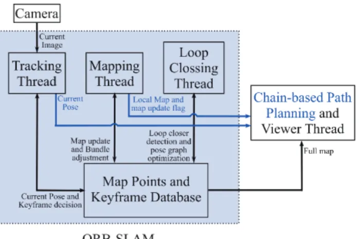
The outline of overall process is shown in the Figure-1. We have added the chain-based path planner in the viewer thread of the ORB-SLAM. It
takes the current pose and map update information for the path generation. In section-2, the chain based path planning algorithm is explained by addressing the issues aroused for urban environments. In section-3, ORB-SLAM procedure is outlined and explained. In section-4, integration of chain-based path planning with ORB-SLAM is presented. In section-5, the simulation and real-time experiment results are shown. Finally, the conclusion is presented in section-6. In Section-7, we presented the possible improvements and limitations in the proposed system
Fig. 1 The overall process flow for obstacle detection and avoidance using ORB-SLAM. The ORB-SLAM sends the current pose and map update information to the chain-based path planner. We did not change the main components in the ORB-SLAM, which is shown as shaded dotted line box. The proposed method is shown as blue color lines and text.
[[UU jjTTiiGGwwGGwwGG
The chain-based path planning algorithm as stated in [26, 27, 28], is used for avoiding collision with intruder aircraft and the test UAV. This algorithm is tested in MATLAB simulation with the assumption that the intruder states are already known to the UAV. In this work, the same algorithm is adopted with the following modifications for the obstacles avoidance in the urban environments.
1) The repulsive force is rotated by 900, when aircraft is approaching exactly opposite to the repulsive force direction of the obstacle (see the Figure-3).
2) More repulsive force is applied to end nodes of the chain i.e. the repulsive force is amplified according to the distance from UAV to the nodes of chain. Nodes which are near to the UAV, more straitening force is applied.
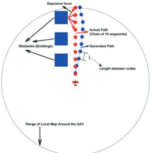
This work generates a collision free path in an urban or indoor environments with a chain of waypoints placed in a virtual force field. The path is represented as series of connected waypoints. The distance between the any two successive waypoints is made equal at all times and is proportional to the UAV speed. This entire process is illustrated in Figure-2. The chain of way points are restricted to move in 2D plane i.e. the aircraft cannot ascent or decent in an urban environment. When the UAV is reached to first node of the chain, the first node is deleted and an extra node is added to the chain in the direction of last edge. These are mathematically described in the next paragraph.
Fig. 2 Chain-based path planning for obstacle avoidance.
Red nodes indicates original waypoints in the absence of obstacles, Blue nodes indicates obstacle avoidance path generated after applying chain-based obstacle avoidance algorithm. The circle around the UAV indicates the assumption of local map build by the UAV using ORB- SLAM technique
.Let 𝒛𝒛𝑖𝑖= (𝑥𝑥𝑖𝑖, 𝑦𝑦𝑖𝑖)𝑇𝑇 ∈ ℝ2 𝑤𝑤ℎ𝑒𝑒𝑒𝑒𝑒𝑒 𝑖𝑖 = 1, 2, … . , 𝑁𝑁 be the position of 𝑖𝑖𝑡𝑡ℎ waypoint and the 𝑁𝑁 link chain can be represented by the following equation.
𝒄𝒄 = [𝒛𝒛1𝑇𝑇, 𝒛𝒛2𝑇𝑇, … … , 𝒛𝒛𝑁𝑁𝑇𝑇]𝑇𝑇 (1)
If chain is placed in a force field, it experiences the force. So according to Newton's second law of motion, the dynamic equation of motion of chain is given by
𝒄𝒄̈ = 𝑭𝑭 (2) Here 𝑭𝑭 is sum of all applied forces acting on the nodes.
There are
three unconstrained forces
acting on the nodes, 1) The attractive force toward the designated goal of UAV and 2) The repulsive force from the obstacle to the UAV and 3) The straitening force.The attractive force is given by
𝑭𝑭𝑎𝑎𝑡𝑡𝑡𝑡𝑎𝑎= −𝛻𝛻𝒇𝒇(𝒛𝒛) (3) Where 𝒇𝒇(𝒛𝒛) is the attractive potential function given by
𝒇𝒇(𝒛𝒛) = 𝜉𝜉 (‖𝒛𝒛𝒊𝒊− 𝒛𝒛𝒈𝒈‖2) (4) Where 𝒛𝒛𝒊𝒊 is 𝑖𝑖𝑡𝑡ℎ way point in the chain, 𝒛𝒛𝒈𝒈 is goal location for the UAV, ‖∙‖ represents the standard Euclidean norm and ξ is a constant scaling parameter.
The distance vector 𝒅𝒅𝑧𝑧𝑧𝑧(𝑛𝑛, 𝑚𝑚) from 𝑚𝑚 𝑡𝑡ℎ obstacle to 𝑛𝑛𝑡𝑡ℎ node of chain given by
𝒅𝒅𝑧𝑧𝑧𝑧(𝑛𝑛, 𝑚𝑚) = 𝒛𝒛𝑛𝑛− 𝒙𝒙𝑚𝑚 (5) Where 𝒙𝒙𝑚𝑚 is the 𝑚𝑚 𝑡𝑡ℎ obstacle position and 𝑚𝑚 = 1, 2 ∙∙∙
∙∙∙ 𝑀𝑀. Where
M
is number of obstacles in local map of UAV. The unit vector in this direction is given by𝐝𝐝̂𝑧𝑧𝑧𝑧(𝑛𝑛, 𝑚𝑚) = ‖𝒅𝒅𝒅𝒅𝑧𝑧𝑧𝑧(𝑛𝑛,𝑚𝑚)
𝑧𝑧𝑧𝑧(𝑛𝑛,𝑚𝑚)‖ (6)
The repulsive force acting on the node 𝑛𝑛 of chain from 𝑚𝑚 𝑡𝑡ℎ obstacle is given by
𝒇𝒇𝑎𝑎𝑟𝑟(𝑛𝑛, 𝑚𝑚) =
{𝐝𝐝̂𝑧𝑧𝑧𝑧(𝑛𝑛, 𝑚𝑚)𝛾𝛾𝑎𝑎𝑟𝑟1𝑒𝑒(−𝛾𝛾𝑟𝑟𝑟𝑟2‖𝒅𝒅𝑧𝑧𝑧𝑧(𝑛𝑛,𝑚𝑚)‖ 𝑛𝑛), 𝑖𝑖𝑖𝑖 ‖𝒅𝒅𝑧𝑧𝑧𝑧(𝑛𝑛, 𝑚𝑚)‖ < 𝑑𝑑𝑚𝑚𝑎𝑎𝑧𝑧
0, 𝑂𝑂𝑂𝑂ℎ𝑒𝑒𝑒𝑒𝑤𝑤𝑖𝑖𝑒𝑒𝑒𝑒
(7) Where 𝑑𝑑𝑚𝑚𝑎𝑎𝑧𝑧 is the minimum safe distance between UAV and the obstacle, 𝛾𝛾𝑎𝑎𝑟𝑟2 & 𝛾𝛾𝑎𝑎𝑟𝑟2 are nonnegative constants. 𝑛𝑛 in the exponential term gives amplification to the distance (‖𝒅𝒅𝑧𝑧𝑧𝑧(𝑛𝑛,𝑚𝑚)‖) according to the distance between UAV and present node. The total force acting on the 𝑛𝑛 𝑡𝑡ℎ node of chain from all the obstacles is given by
𝑭𝑭𝑎𝑎𝑟𝑟𝑧𝑧𝑧𝑧(𝑛𝑛) = ∑𝑀𝑀𝑚𝑚=1𝒇𝒇𝑎𝑎𝑟𝑟(𝑛𝑛, 𝑚𝑚) (8) So the total repulsive force acting on the corresponding chain nodes is
𝑭𝑭𝑎𝑎𝑟𝑟𝑧𝑧𝑧𝑧= [𝑭𝑭𝑎𝑎𝑟𝑟𝑧𝑧𝑧𝑧𝑇𝑇 (1), 𝑭𝑭𝑎𝑎𝑟𝑟𝑧𝑧𝑧𝑧𝑇𝑇 (2), 𝑭𝑭𝑎𝑎𝑟𝑟𝑧𝑧𝑧𝑧𝑇𝑇 (1) ∙∙∙∙∙∙∙∙∙∙∙ 𝑭𝑭𝑎𝑎𝑟𝑟𝑧𝑧𝑧𝑧𝑇𝑇 (𝑁𝑁)]𝑇𝑇
(9)
The drawback in this approach is, When UAV is approaching exactly opposite to the repulsive force
from obstacle, the nodes get repelled towards the UAV. Because of this, the distance between chain nodes and minimum turn angle between the edges of chain gets disturbed. To overcome this issue, the repulsive force is rotated by 900 whenever the angle between repulsive force and the UAV heading is
±1800 as shown in the Figure-3.
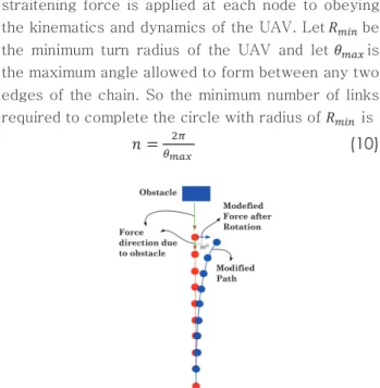
To maintain the minimum turn radius of the UAV, a straitening force is applied at each node to obeying the kinematics and dynamics of the UAV. Let 𝑅𝑅𝑚𝑚𝑚𝑚𝑚𝑚 be the minimum turn radius of the UAV and let 𝜃𝜃𝑚𝑚𝑚𝑚𝑚𝑚 is the maximum angle allowed to form between any two edges of the chain. So the minimum number of links required to complete the circle with radius of 𝑅𝑅𝑚𝑚𝑚𝑚𝑚𝑚 is
𝑛𝑛 =
𝜃𝜃2𝜋𝜋𝑚𝑚𝑚𝑚𝑚𝑚
(10)
Fig. 3 Illustration of repulsive force opposite to the UAV heading and modified path after force rotation.
Fig. 4 Approximation of closed loop chain with a circle of radius 𝑅𝑅
𝑚𝑚𝑚𝑚𝑚𝑚to find maximum allowable turn angle 𝜃𝜃
𝑚𝑚𝑚𝑚𝑚𝑚.
From the Figure-4, the total length of closed chain path around circle with radius 𝑅𝑅𝑚𝑚𝑚𝑚𝑚𝑚 should be greater than or equal to circumference of the circle.
𝑖𝑖. 𝑒𝑒. 𝑛𝑛𝑛𝑛 ≥ 2𝜋𝜋𝑅𝑅𝑚𝑚𝑚𝑚𝑚𝑚 (11) From Equations (10) and (11), we get
𝜃𝜃𝑚𝑚𝑚𝑚𝑚𝑚 ≤ 𝑅𝑅𝐿𝐿
𝑚𝑚𝑚𝑚𝑚𝑚 (12)
A straightening force 𝒇𝒇𝑠𝑠𝑠𝑠(𝑖𝑖) is applied at each node such that the turn angle at each node must be less
than 𝜃𝜃𝑚𝑚𝑚𝑚𝑚𝑚 i.e. 𝜃𝜃𝑚𝑚< 𝜃𝜃𝑚𝑚𝑚𝑚𝑚𝑚 . Where 𝜃𝜃𝑚𝑚 is the angle between the vectors 𝒅𝒅𝑚𝑚2 𝑎𝑎𝑛𝑛𝑎𝑎 𝒅𝒅𝑚𝑚1 as shown in the Figure-5. Where 𝒅𝒅𝑚𝑚1= 𝒛𝒛𝑁𝑁−1− 𝒛𝒛𝑁𝑁−2 and 𝒅𝒅𝑚𝑚2= 𝒛𝒛𝑁𝑁−2− 𝒛𝒛𝑁𝑁−3, then the straightening force is given by
𝒇𝒇𝑠𝑠𝑠𝑠(𝑖𝑖) =1+exp (𝑘𝑘(𝜃𝜃𝜇𝜇𝑚𝑚(𝒅𝒅𝑚𝑚1𝑚𝑚𝑚𝑚𝑚𝑚)⊥−𝜃𝜃𝑚𝑚) (13) Where 𝑖𝑖 = 1, 2,∙∙∙∙∙∙∙∙, 𝑁𝑁 . The upper limit on the straightening force for the node 𝑖𝑖 is 𝜇𝜇𝑚𝑚= (𝑁𝑁 + 1 − 𝑖𝑖). 𝑘𝑘 is a positive constant and (𝒅𝒅𝑚𝑚1)⊥ is the perpendicular component of the vector 𝒅𝒅𝑚𝑚1.
Fig. 5 Illustration of straightening force at node 𝒛𝒛
𝑁𝑁−1.
The vector 𝑭𝑭𝑠𝑠𝑠𝑠= [𝒇𝒇𝑠𝑠𝑠𝑠𝑇𝑇(1), 𝒇𝒇𝑠𝑠𝑠𝑠𝑇𝑇(2), … … … . . , 𝒇𝒇𝑠𝑠𝑠𝑠𝑇𝑇(𝑁𝑁)]𝑇𝑇 is the straitening forces acting on all the nodes. Then the total force is defined as𝑭𝑭 = 𝑭𝑭𝒂𝒂𝒂𝒂𝒂𝒂𝒂𝒂+ 𝑭𝑭𝒂𝒂𝒓𝒓𝒛𝒛𝒓𝒓+ 𝑭𝑭𝒔𝒔𝒂𝒂 (14) Apart from these unconstrained forces, an extra- constrained force is applied to maintain an equal length between the chain nodes. Let 𝑛𝑛 be the desired length of each edge in the chain. Similar to [27], this constraint can be written as
[
‖𝒛𝒛2− 𝒛𝒛1‖2− 𝑛𝑛2
‖𝒛𝒛3− 𝒛𝒛2‖2− 𝑛𝑛2
‖𝒛𝒛𝑁𝑁− 𝒛𝒛𝑁𝑁−1⋮ ‖2− 𝑛𝑛2]
= 0 (15)
Differentiating the above equation-(15) once, we get the velocity constraints
[
2(𝒛𝒛2− 𝒛𝒛1)𝑇𝑇(𝒛𝒛̇2− 𝒛𝒛̇1) 2(𝒛𝒛3− 𝒛𝒛2)𝑇𝑇(𝒛𝒛̇3− 𝒛𝒛̇2) 2(𝒛𝒛𝑁𝑁− 𝒛𝒛𝑁𝑁−1)⋮𝑇𝑇(𝒛𝒛̇𝑁𝑁− 𝒛𝒛̇𝑁𝑁−1)]
= 0 (16)
Differentiating once again, we get the acceleration constraints
𝑨𝑨(𝒄𝒄)𝒄𝒄̈ = 𝒃𝒃(𝒄𝒄̇) (17) Where
𝑨𝑨(𝒄𝒄) =
[
(𝒛𝒛𝟐𝟐− 𝒛𝒛𝟏𝟏)𝑇𝑇 0 … 0
−(𝒛𝒛𝟑𝟑− 𝒛𝒛𝟐𝟐)𝑇𝑇 (𝒛𝒛𝟑𝟑− 𝒛𝒛𝟐𝟐)𝑇𝑇 … 0
⋮ ⋱ ⋱ ⋮
0 … −(𝒛𝒛𝑵𝑵−𝟐𝟐− 𝒛𝒛𝑵𝑵−𝟏𝟏)𝑻𝑻 (𝒛𝒛𝑵𝑵−𝟐𝟐− 𝒛𝒛𝑵𝑵−𝟏𝟏)𝑻𝑻
0 ⋯ 0 −(𝒛𝒛𝑵𝑵− 𝒛𝒛𝑵𝑵−𝟏𝟏)𝑻𝑻]
(18)
And
𝒃𝒃(𝒄𝒄) = − [
(𝒛𝒛̇𝟐𝟐− 𝒛𝒛̇𝟏𝟏)𝑇𝑇(𝒛𝒛̇𝟐𝟐− 𝒛𝒛̇𝟏𝟏) (𝒛𝒛̇𝟑𝟑− 𝒛𝒛̇𝟐𝟐)𝑇𝑇(𝒛𝒛̇𝟑𝟑− 𝒛𝒛̇𝟐𝟐) (𝒛𝒛̇𝑵𝑵− 𝒛𝒛̇𝑵𝑵−𝟏𝟏)𝑇𝑇⋮(𝒛𝒛̇𝑵𝑵− 𝒛𝒛̇𝑵𝑵−𝟏𝟏)]
(19)
With the above acceleration constraints, the equation of motion of system (2) becomes
𝒄𝒄̈ = 𝑭𝑭 + 𝑨𝑨+(𝒄𝒄)[𝒃𝒃(𝒄𝒄̇) − 𝑨𝑨(𝒄𝒄)𝑭𝑭] (20) Where 𝑨𝑨+ is the pseudo-inverse of
A A
. By solving the above ordinary differential equation, we generate the obstacle avoidance path with minimum turn radius and equal edge lengths. This method has an advantage of applying potential fields only to the chain nodes instead of applying at each point of the environment. If the local map of the environment is very large, the classical ordinary potential field methods consume lot of time. The second advantage is that, this approach can also be used to generate avoidance path for the dynamic obstacles.\\UU v vyyiiTTzzsshht tGG
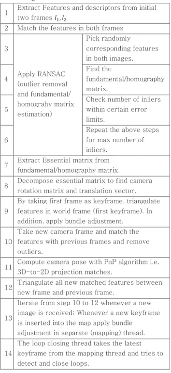
When compared with other keyframe-based SLAM techniques, the ORB-SLAM has the following advantages, a) the method uses same features for all tasks of tracking, mapping, re-localization and loop closing. The use of ORB features allows real time performance without GPU, b) Real time camera relocalization even when there is a significant invariance to view point and illumination. c) Automatic map initialization for planar and non- planar scenes based on model selection. The ORB- SLAM uses four threads running in parallel, 1) Tracking thread, 2) Local Mapping thread, 3) Loop closing thread and 4) Viewer thread. The overall process is shown in Figure-1 and briefly explained in the Table-1. As stated in [7], the accuracy of the system is less than below 1cm in indoor environments and of a few meters in outdoor environments. This is the most reliable and complete solution to monocular-SLAM. The map is updated with new 3D points whenever a keyframe from the tracking thread is received. If the current frame is not a keyframe, the tracked features are used as measurements for the corresponding 3D points to improve the depth accuracy. The mapping thread is running at lower rate than tracking thread, i.e. it executes at a keyframe rate instead of camera frame rate. So the costly (computation power) extraction of environment information from the images is done in
the mapping thread, this helps to get the real-time pose output at camera frame rate (20~30 frames/sec) from tracking thread. The mapping thread provides the obstacles position information directly to the path planning algorithm.
Table 1 Explanation of different basic steps in ORB- SLAM algorithm
1 Extract Features and descriptors from initial two frames 𝐼𝐼1, 𝐼𝐼2
2 Match the features in both frames
3
Apply RANSAC (outlier removal and fundamental/
homograhy matrix estimation)
Pick randomly
corresponding features in both images.
4
Find the
fundamental/homography matrix.
5
Check number of inliers within certain error limits.
6
Repeat the above steps for max number of inliers.
7 Extract Essential matrix from fundamental/homography matrix.
8 Decompose essential matrix to find camera rotation matrix and translation vector.
9
By taking first frame as keyframe, triangulate features in world frame (first keyframe). In addition, apply bundle adjustment.
10
Take new camera frame and match the features with previous frames and remove outliers.
11 Compute camera pose with PnP algorithm i.e.
3D-to-2D projection matches.
12 Triangulate all new matched features between new frame and previous frame.
13
Iterate from step 10 to 12 whenever a new image is received; Whenever a new keyframe is inserted into the map apply bundle
adjustment in separate (mapping) thread.
14
The loop closing thread takes the latest keyframe from the mapping thread and tries to detect and close loops.
]]UU jjGGhhGGGGGGppGGGG v
vyyiiTTzzsshht tGG~ ~GGjjTTiiGGwwGG wwGG
In this paper, a major aim of the work is to provide a robust and real time process for obstacle detection and path planning using the ORB-SLAM approach and the chain-based path planning method as outlined in Section 4 and 5. Towards this, the chain- based path planning algorithm is included in the viewer thread of ORB-SLAM. In the viewer thread, this process is running at lower rate than frame rate because ORB-SLAM updates the map only when it encounters a new keyframe. When a keyframe is received in mapping thread, it triangulates the 3D position of the new features by using the pose information from tracking thread then it refines the pose and features depth estimates using bundle adjustment procedure. So the chain-based path planner is executed whenever there is a map update flag from the ORB-SLAM. By taking the map update flag and the full map (3D positions), the obstacle map is generated around the current position of the UAV.
Table 2 Chain-based path planning with ORB-SLAM outline
1
Initialize the local map (5m x 5m) around the current position of UAV with ORB-SLAM algorithm’s full map and local map.
2
Initialize the chain of way points in front of UAV/camera.
Let camera position in world coordinates given by 𝒛𝒛𝑐𝑐= [𝑥𝑥, 𝑦𝑦, 𝑧𝑧].
Then chain nodes are given by 𝒄𝒄 = [𝒛𝒛𝒄𝒄+ 4𝒗𝒗, 𝒛𝒛𝒄𝒄+ 8𝒗𝒗, 𝒛𝒛𝒄𝒄+ 12𝒗𝒗, 𝒛𝒛𝒄𝒄+ 16𝒗𝒗, 𝒛𝒛𝒄𝒄+ 20𝒗𝒗]. Where 𝑣𝑣 is the current velocity of the UAV.
3
When ORB-SLAM builds the map of the
environment locally (mapping thread), the chain- based path planning algorithm checks for collision detection with the chain nodes.
4
If obstacles (3D voxels with threshold volume) are within the threshold distance from the chain nodes, apply the procedure given in section-2.
5 Move the UAV/camera towards first chain node.
6
When UAV/camera is near to first node delete it and extend the chain with another node at the end in the direction of last edge.
Here the sparse map points are assumed to be 3D voxels having certain threshold volume. The scale information of the monocular-SLAM is provided with user interface by estimating the depth of objects in front of the camera at the initialization phase. This process is further outlined in Table-2.
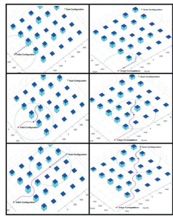
^^UU zz GGGGyyGG{{ GGll GG yyGG
For the simulation of chain-based path planning algorithm, a map of city is simulated in Matlab with building length and width of 100m and random heights. The assumption for Matlab simulation is that the UAV can able to build the local map using the vision-based techniques, which has been shown as blue color circle around the UAV in figure-6. For every iteration, the obstacle positions within the local map are given as input for the chain-based path planning algorithm. Using this positions, first a collision check is performed at each and every node of chain. If obstacles are within certain threshold range, apply the chain-based path planning algorithm.
Fig. 6 Simulation results of Chain-Based path planner at different time instants (from top to bottom column wise).
Here a chain of ten way points are generated with blue color circles on which different types of forces are acting, static obstacles (buildings) are shown in magenta with top blue color and the pink color dotted line indicates the traversed path. The corresponding videos of the experiments can be found in the following links:
https://youtu.be/Ex7SRJI8uiY, https://youtu.be/k- rYVg0kF2U and https://youtu.be/VXpgs1_G0D0
The path managing (dubins path), path following and guidance models for the fixed wing UAV are adopted from the text book [29]. The simulation results are shown in the Figure-6 for different scenarios at different time instants, where the chain is shown as blue color small circles in front of UAV, the traversed path is shown as pink color dotted line and static obstacles (buildings) are shown in magenta with top as blue color.
The Monocular ORB-SLAM experiments are conducted in a laptop having Intel i7 processor with 8GB RAM and 2.8GHz speed. The laptop is attached with a Logitech camera with 640×480 resolution and other equipment as shown in figure-7.
Fig. 7 Hardware setup for the real-world experiments on ORB-SLAM and chain-based path planning.
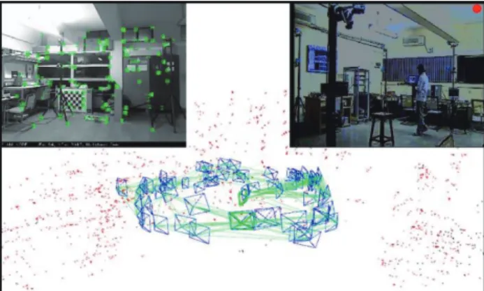
The camera is moving in a circular trajectory. The generated map and the trajectory while experiment is conducting are shown in figure-8. The camera intrinsic parameters are pre-calibrated with Matlab calibration toolbox. The full trajectory along with the map are plotted in offline is shown in figure-9. The generated trajectory from ORB-SLAM is compared with the optitrack [30] position values. The markers
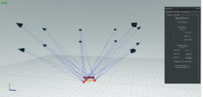
of optitrack system are attached to the laptop, which helps to estimate the 6DOF motion of the rigid body at high rate (200Hz) with millimeter accuracy. The snapshot of motive software for the optitrack system (after calibration) with its 12 high speed cameras are shown in figure-10. Here, we compare the Euclidian position change from the reference point selected at particular instant of time and position from both SLAM and optitrack systems. The optitrack position values are receiving in the laptop via the xbee modules as shown in the figure-7. The position change from an arbitrary reference points of both ORB-SLAM and ground truth optitrack are shown in the figure-11.
Fig. 8 The top left figure shows the current image with extracted and tracked ORB features from tracking thread.
The top right figure shows the secondary camera image
for external view on the experiment. The bottom one is
the generated map and camera poses estimated by the
ORB-SLAM. This experiment is used for the evaluation
for the estimated trajectory with ground truth trajectory
from optitrack system. The experiment video can be
found by the link https://youtu.be/qkynUEBxcuk.
Fig. 9
The final estimated monocular-camera based ORB- SLAM trajectory and environment map of the above experiment.
From the above figures, we conclude that the position estimates and map points meet the required accuracy (position error is within 1m range) range for the obstacle avoidance algorithm.
The real-data experiments on chain-based path planning with ORB-SLAM is shown in Figure-12 and its accompanying video link is given in the figure. In this experiment, the camera is moved manually towards the waypoints and the chain is continuously repelling from the obstacles coming from the SLAM map (when the mapping thread adds the 3D points).
These experiments are conducted in a lab environment in near real time scenario, where the ORB-SLAM is reconstructing the monitor and keyboard in front of the camera and the chain-based path planer generates a path to avoid these obstacles.
Fig. 10 The snapshot of the motive software for the optitrack system. The rigid body under experiment can be seen in the middle with a triangular shape. The 12 high- speed cameras are distributed around the configuration space volume for the maximum coverage. The position and orientation estimation of the rigid body can be seen on the right side of the figure.
Fig. 11 The comparison between the estimated camera positions from the ORB-SLAM with optitrack positions.
Since the reference frames of both systems are different, the Euclidean norm on the position change with respect to a reference points at same instant of time and position from both system are calculated.
The chain nodes are continuously getting more repulsion force from the obstacles as the mapping module adds the more 3D points. At the initial stage, we generated the waypoints exactly in front of the camera. The first part of the figure-12 shows the quick repulsion from the obstacles. Since at the initial stage, the camera velocity is almost zero. So the camera can take quick turn towards the left side, this can be seen from the figure first part. While camera is in motion, the path planner is able to take velocity constraints (i.e. minimum turn radius with given velocity), which can be seen as a more straitening force in the next parts of the figure-12 (waypoints are in front of the present orientation of camera). Since the camera is manually moved towards the chain nodes, the velocity along the edges is very small (in the order of ~1m). So in the last part of the figure-12 is having more turn radius between the first and second edge. From this, we conclude that, the chain-based path planner with ORB-SLAM is able to generate real-time feasible obstacle avoidance paths with less complexity in the potential fields generation. The limitations and further improvements in the proposed method is discussed in the section-7.
Fig. 12 Real Time Path Generation at Different Time Instants with ORB-SLAM (The chain of way points are indicated with Pink color spears, The camera is represented by green box, obstacles in the current frame are indicated with red color dots and past frames obstacles are indicated with black color dots). This experiment video can be found in the link:
https://youtu.be/EpFHhlDZwDI
__UU jjGG
In this paper, we have implemented a near real time UAV navigation in GPS denied environments for obstacle avoidance with vision as primary sensor for mapping the environment and localizing the UAV position in the environment. We have used the chain- based path planning approach based on potential fields to avoid the obstacles in the environment. We addressed the two issues related with chain-based path planning for urban environments. The entire algorithm is integrated in ORB-SLAM method to get the map of the environment and also for the position of UAV purely from onboard sensors.
``UU ss GGGGmmGG~ ~
The problems with sparse map from ORB-SLAM is, 1) It detects only the point features in the given images, which is not sufficient for detecting obstacle boundary and 2) If there is no feature in the image it treats as no obstacle, which will be the wrong choice if UAV is near to the wall where no features are found. The first problem is addressed in this paper with an assumption of 3D voxels around the point features. However, this is not sufficient for the accurate boundary detection for the obstacles. The second problem can be omitted in the outside urban environments because features are definitely find in these environments. Therefore, we are concentrating on the first issue of sparse map for detecting the boundaries of obstacles for effective avoidance maneuvers.
yy
[1] D. Mellinger and V. Kumar, "Minimum snap trajectory generation and control for quadrotors," in IEEE Intl. Conf.
on Robotics and Automation (ICRA), 2011.
[2] S. Lupashin, A. Schollig, M. Sherback, and R. D’Andrea,
"A simple learning strategy for high-speed quadrocopter multi-flips.," in IEEE Intl. Conf. on Robotics and Automation (ICRA), 2010.
[3] Q. Lindsey, D. Mellinger, and V. Kumar, "Construction of cubic structures with quadrotor teams," in Robotics:
Science and Systems (RSS), Los Angeles, CA, USA, 2011.
[4] M. Colton, L. Sun, D. Carlson, and R. Beard, "Multi- vehicle dynamics and control for aerial recovery of micro air vehicles," International Journal of Vehicle Autonomous Systems, vol. Volume 9, no. 1-2, 2011.
[5] C. Forster, M. Pizzoli, and D. Scaramuzza, "SVO : Fast Semi Direct Monocular Visual Odometry," in IEEE Intl.
Conf. on Robotics and Automation (ICRA), 2014.
[6] Georg Klein, David Murray, "Parallel Tracking and Mapping for Small AR Workspaces," in IEEE and ACM International Symposium on Mixed and Augmented Reality, 2008.
[7] Raúl Mur-Artal, J. M. M. Montiel and Juan D. Tardós,
"ORB-SLAM: A Versatile and Accurate Monocular SLAM System," IEEE Transactions on Robotics, vol. 31, no. 5, pp. 1147-1163, 2015.
[8] J. Engel and T. Schops and D. Cremers, "LSD-SLAM:
Large-Scale Direct Monocular SLAM," in European Conference on Computer Vision (ECCV), 2014.
[9] Bai, G., X. Xiang, H. Zhu, D. Yin, and L. Zhu, "Research on Obstacles Avoidance Technology for UAV Based on Improved PTAM Algorithm," in IEEE International Conference on Progress in Informatics and Computing, Nanjing, China, 2015.
[10] Omid Esrafilian, Hamid D. Taghirad, "Autonomous Flight and Obstacle Avoidance of a Quadrotor By Monocular SLAM," in Proceedings of the 4th International Conference on Robotics and Mechatronics, Tehran, Iran, 2016.
[11] Fei Gao, Yi Lin and Shaojie Shen, "Gradient-Based Online Safe Trajectory Generation for Quadrotor Flight in Complex Environments," in IEEE/RSJ Intl. Conf. on Intell. Robots and Syst, Vancouver, Canada, 2017.
[12] Grzonka, S., Grisetti, G., Burgard, W, "A fully autonomous indoor quadrotor," IEEE Transactions on Robotics, pp. 90-100, 2012.
[13] Bachrach, A., de Winter, A., He, R., Hemann, G., Prentice, S., Roy, N, "RANGE - robust autonomous navigation in GPS-denied environments," in International Conference on Robotics and Automation (ICRA), 2010.
[14] J Engel, J Sturm, D Cremers, "Camera-Based Navigation of a Low-Cost Quadrocopter," in IEEE/RSJ International conference on Intelligent Robots and Systems (IROS), 2012.
[15] Fraundorfer, F., Heng, L., Honegger, D., Lee, G., Meier, L., Tanskanen, P., Pollefeys, M., "Vision-based autonomous mapping and exploration using a quadrotor MAV," in IEEE/RSJ International Conference on Intelligent Robots and Systems (IROS), 2012.
[16] Wagter, C.D., Tijmons, S., Remes, B., de Croon, G.,
"Autonomous flight of a 20-gram flapping wing mav with a 4-gram onboard stereo vision system," in International Conference on Robotics and Automation (ICRA), 2014.
[17] Huang A.S., Bachrach A., Henry P., Krainin M., Maturana D., Fox D., Roy N., "Visual odometry and mapping for autonomous flight using an RGB-D camera," in Int.
Symposium on Robotics Research (ISRR), 2011.
[18] Tomic T., Schmid K., Lutz P., Domel A., Kassecker M., Mair E., Grixa I.L., Ruess F.,Suppa M., Burschka D.,
"Toward a fully autonomous UAV: Research platform for indoor and outdoor urban search and rescue," IEEE Robotics & Automation Magazine, pp. 46-56, 2012.
[19] Nieuwenhuisen M., Droeschel D., Holz D., Laebe T., Behnke S., "Multimodal obstacle detection and collision avoidance for micro aerial vehicles," in European Conference on Mobile Robots (ECMR), 2013.
[20] Andrew J. Davison , Ian D. Reid, Nicholas D. Molton,
"MonoSLAM: Real-Time Single Camera SLAM," IEEE Transactions on Pattern Analysis and Machine Intelligence, vol. 29, no. 6, pp. 1052 - 1067, 2007.
[21] B. Triggs; P. McLauchlan; R. Hartley; A. Fitzgibbon,
"Bundle Adjustment — A Modern Synthesis," in International Workshop on Vision Algorithms (ICCV), 1999.
[22] H. Strasdat, J. Montiel, and A. Davison, "Real-time monocular SLAM: Why filter?," in International Conference on Robotics and Automation (ICRA), 2010.
[23] Abdulla Al-Kaff, Qinggang Meng, David Martin, Arturo de la Escalera, Jose MariaArmingol, "Monocular Vision- Based Obstacle Detection/Avoidance for Unmanned Aerial Vehicles," in IEEE Intelligent Vehicles Symposium (IV), Gothenburg, Sweden, 2016.
[24] Yuncheng Lu, Zhucun Xue, Gui-Song Xia & Liangpei Zhang, "A survey on vision-based UAV navigation," Geo- spatial Information Science, vol. 21, no. 1, pp. 21-32, 2018.
[25] Bortoff, S. A, "Path Planning for UAVs," in American Control Conference, IEEE, Chicago, IL, USA, 2000.
[26] McLain T. W. and Beard R. W., "Trajectory Planning for Coordinated Rendezvous of Unmanned Air Vehicles," in American Institute of Aeronautics and Astronautics, Inc (AIAA), 2000.
[27] Argyle M., Chamberlain C., and Beard R., "Chain-Based Path Planning for Multiple UAVs," in IEEE Conference on Decision and Control and European Control Conference, 2011.
[28] Laith R. Sahawneh and Randal W. Beard, "Chain-based Collision Avoidance for UAS," in AIAA Guidance, Navigation, and Control (GNC) Conference, 2013.
[29] Beard R.W. and McLain T.W, Small Unmanned Aircraft:
Theory and Practice, Princeton University Press, 2012.
[30] Natural Point Inc., "Natural Point Optitrack System Documentation,"
https://v20.wiki.optitrack.com/index.php?title=OptiTrack _Documentation_Wiki.
hhGGhhaaGGzzGGpp GG
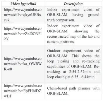
Table A1 Hyperlinks to multimedia extensions on real- time experiments.
Video hyperlink Description https://www.youtube.co
m/watch?v=qkynUEBx cuk
Indoor experiment video of ORB-SLAM having ground truth comparison.
https://www.youtube.co m/watch?v=zZzJ0ON6l 2Y
Indoor experiment video of ORB-SLAM showing the reconstructed map of the lab and camera positions.
https://www.youtube.co m/watch?v=ka_OWRW K-o0
Outdoor experiment video of ORB-SLAM. This shows the loop closing and re-tracking capabilities of ORB-SLAM. Re- tracking at 2:54-2:57min and loop closing at 6:35 –6:44min.
https://www.youtube.co m/watch?v=EpFHhlDZ wDI
Chain-based path planner with ORB-SLAM.