대한치과교정학회 임상저널
대한치과교정학회
Volume 11 Number 1 March 2021 pISSN 2733-6026 eISSN 2384-1230 http://kao.or.kr/cjkao
편집위원회
편집위원장
채 종 문 (원광대학교)
편집이사
장 인 산 (강릉원주대학교)
편집위원
안 효 원 (경희대학교) 최 동 순 (강릉원주대학교)
임 승 원 (전남대학교) 홍 미 희 (경북대학교)
이 경 민 (전남대학교) 이 상 민 (단국대학교)
김 용 일 (부산대학교) 안 정 섭 (서울대학교)
이 승 엽 (전북대학교) 이 미 영 (관악서울대학교치과병원)
최 윤 정 (연세대학교) 임 성 훈 (조선대학교)
영문교정 편집위원 장 나 영 (원광대학교)
통계 편집위원 서 혜 영 (원광대학교)
Editorial Board
Editor-in-Chief
Jong-Moon Chae(Wonkwang University)
Deputy Editor
Insan Jang (Gangneung-Wonju National University)
Editorial Board
Hyo-Won Ahn (Kyung Hee University) Dong-Soon Choi (Gangneung-Wonju National University) Seung-weon Lim (Chonnam National University) Mihee Hong (Kyungpook National University)
Kyung-Min Lee (Chonnam National University) Sang-Min Lee (Dankook University) Yong-Il Kim (Pusan National University) Jung-Sub An (Seoul National University)
Seung-Youb Lee (Chonbuk National University) Mi-Young Lee (Seoul National University Gwanak Dental Hospital) Yoon-Jeong Choi (Yonsei University) Sung-Hoon Lim (Chosun University)
English Manuscript Editor Na-young Chang (Wonkwang University) Biostatistical Reviewer
Hye Young Seo (Wonkwang University)
iv
대한치과교정학회 임상저널
2021년 11권 1호 3월호 ORIGINAL ARTICLE
Bone Density Measurements: Multi-Slice Computed Tomography versus Cone-Beam Computed Tomography
Mi-Young Lee, Jae Hyun Park, Na-Young Chang, Hye Young Seo,
Jong-Moon Chae ··· 1
CASE REPORT
구호흡을 가진 성장기 골격성 II급 부정교합 환자에서 편도/아데노이드 절제술과 구강근기능요법을 동반한 성장 조절 치험례
안성재, 안효원, 김수정, 김경아 ··· 11
미니 임플랜트를 이용한 상·하악 치열의 크라우딩과 횡적 부조화를 동반한 골격성 Ⅲ급 부정교합 환자의 절충 치료 치험례
이바울 ··· 22
Open Surgical Exposure와 Bone-Anchored Pendulum을 이용한 구개측 견치 매복 환자의 치험례
안재화, 김성훈, 김용일, 김성식, 박수병, 손우성 ··· 35
편측성과 양측성 가위교합을 가진 일란성 쌍둥이의 치료
김석구 ··· 46
원내 커스텀 처방 브라켓을 이용한 골격성 III급 부정교합 환자의 절충 치험례
김도현 ··· 62
Gummy Smile과 과개교합을 동반한 II급 부정교합 환자의 미니스크루를 이용한 비발치 교정치료
강시원 ··· 76
투고안내
3 A dry mandible and resin template
14 Adenotonsillectomy
48 Brodie bite
68 Customized resin-based bracket on 3D printed model
27 MSE, facemask, and Class III elastics
40 Bone-anchored pendulum appliance
86 Force system for gummy smile correction
3 A dry mandible and resin template
14 Adenotonsillectomy
48 Brodie bite
68 Customized resin-based bracket on 3D printed model
27 MSE, facemask, and Class III elastics
40 Bone-anchored pendulum appliance
86 Force system for gummy smile correction
Clinical Journal of Korean Association of Orthodontists
Vol 11 No 1 March 2021 ORIGINAL ARTICLE
Bone Density Measurements: Multi-Slice Computed Tomography versus Cone-Beam Computed Tomography
Mi-Young Lee, Jae Hyun Park, Na-Young Chang, Hye Young Seo,
Jong-Moon Chae ··· 1
CASE REPORT
Growth Modification Treatment of Skeletal Class II Growing Patient with Mouth Breathing Using Adenotonsillectomy and Myofunctional Therapy
Sung-Jea Ahn, Hyo-Won Ahn, Su-jung Kim, Kyung-A Kim ··· 11
Camouflage Treatment of Skeletal Class III Patient with Crowding and Transverse Discrepancy Using Orthodontic Mini-Implant
Ba-Wool Lee ··· 22
Treatment of Unilateral and Bilateral Posterior Scissors-Bite in Monozygotic Twins
Seok-Goo Kim ··· 46
Camouflage Treatment of Skeletal Class III Malocclusion with In-Office Customized Prescription Bracket: A Case Report
Do-Hyun Kim ··· 62
Nonextraction Treatment of a Class II Malocclusion Patient with a Deepbite and Gummy Smile Using Miniscrew Anchorage
Si-Won Kang ··· 76
Information for Authors
Orthodontic Treatment with Open Surgical Exposure and Bone- Anchored Pendulum for a Patient with Palatally Impacted Canine
Jae-Hwa An, Sung-Hun Kim, Yong-Il Kim, Seong-Sik Kim, Soo-Byung Park,
Woo-Sung Son ··· 35
pISSN 2733-6026 / eISSN 2384-1230 Clin J Korean Assoc Orthod 2021;11(1):1-10 https://doi.org/10.33777/cjkao.2021.11.1.1
Dr. 채 종 문 Dr. 서 혜 영
Dr. 장 나 영 Dr. 박 재 현
Dr. 이 미 영
Corresponding author: Jong-Moon Chae Department of Orthodontics, School of Dentistry, Wonkwang University, Daejeon Dental Hospital, 77 Dunsan-ro, Seo-gu, Daejeon 35233, Korea Tel: +82-42-366-1103 Fax: +82-42-366-1115 E-mail: [email protected] Received: January 23, 2021 / Revised: February 4, 2021 / Accepted: February 4, 2021
ABSTRACT
Introduction: The purpose of this study was to compare and evaluate the bone density values obtained by using multi- slice computed tomography (MSCT) vs. cone-beam computed tomography (CBCT). Methods: A dry mandible was scanned with MSCT (Hounsfield unit; HU) and 3 types of CBCTs (voxel value; VV). Bone densities (gray scales) in the scanned images were measured and compared using 3-dimensional software programs. The cortical, cancellous and total bone densities of the alveolar bone between the mandibular second premolar and first molar were measured on an axial slice at the height of 3, 6, and 9 mm apically from the alveolar crest. Results: There was no statistical dif- ference in bone density between the right and left sides. The cortical bone density measurements were significantly different with MSCT vs. CBCT (P<0.05), but there were no significant differences in cancellous and total bone densi- ty measurements with MSCT vs. CBCT (P>0.05). The bone density values showed linear relationships in the MSCT and CBCT images. Conclusions: Bone density values were different but showed linear relationships in MSCT and CBCT images. Therefore, CBCT could be a valuable tool for evaluating bone density on a relative basis. (Clin J Ko- rean Assoc Orthod 2021;11(1):1-10)
Key words Bone density, CBCT, MSCT, Hounsfield unit, Voxel value
Bone Density Measurements: Multi-Slice Computed Tomography versus Cone-Beam Computed Tomography
Mi-Young Lee,1 Jae Hyun Park,2,3 Na-Young Chang,4 Hye Young Seo,5 Jong-Moon Chae2,4
1Department of Orthodontics, Gwanak Seoul National University Dental Hospital, Seoul, Korea
2Postgraduate Orthodontic Program, Arizona School of Dentistry & Oral Health, A.T. Still University, Mesa, Arizona, USA
3International Scholar, Graduate School of Dentistry, Kyung Hee University, Seoul, Korea
4Department of Orthodontics, School of Dentistry, University of Wonkwang, Wonkwang Dental Research Institute, Iksan, Korea
5School of Big Data and Financial Statistics, College of Natural Sciences, University of Wonkwang, Iksan, Korea
ORIGINAL ARTICLE
2
Clin J Korean Assoc Orthod 2021;11(1):1-10
INTRODUCTION
Cone-beam computed tomography (CBCT) is an image system that offers more advantages than multi-slice computed tomography (MSCT) in den- tistry. Bone quality and bone density can be de- termined by CBCT during dental implant place- ment; it is used to evaluate bone height and width, distance from anatomical structures such as the mandibular canal and maxillary sinus, and the stability of dental implants.1 Moreover, when or- thodontic micro-implants are placed in patients who are undergoing orthodontic treatment, CBCT allows for the measurement of bone density and cortical bone thickness.2,3 CBCT is commonly used in dentistry because it involves a relatively low dosage of radiation exposure in patients, re- quires only a short measurement time, is low cost, and produces images of relatively high resolution.
However, compared to MSCT, CBCT exhibits stronger beam hardening artifacts and scattered radiation which lead to fundamental problems in measuring bone density and quality.4
Bone quality is a comprehensive term that en- compasses bone physiology, degree of mineral- ization, morphology and the type of trabecular pattern. Importantly, it is difficult to accurately measure bone quality.5 Although ultrasound as- sessment may be performed, this method is dif- ficult to use in dentistry. Therefore, radiographic imaging, which is relatively easy and noninvasive, is used to measure bone quality, but CBCT is al- so selected for this purpose.6 While methods to measure bone quality on radiographs have not yet been standardized, the Lekholm and Zarb7 classi- fication is often used. In this case, bone quality is divided into four categories depending on the de- gree of cortication and trabecular bone morpholo- gy, which have to be subjectively evaluated by the observer.
Hounsfield units (HU) are used to measure bone density with CT. HU are standard numbers that originate from CT imaging; they represent the relative density of body tissues according to a calibrated gray-level scale, based on values for air (-1,000 HU), water (0 HU), and bone density (+1,000 HU). With CBCT, the degree of X-ray at- tenuation is shown as a gray scale (voxel value).
While CBCT manufacturers and software pro- viders provide gray scales in HU, these measure- ments are not strictly in HU.1,8,9
Recent developments in CBCT have enabled 3-dimensional measurement of bone density, al- though the accuracy of the method remains con- troversial. Some studies4,10 have shown a linear relationship between HU with MSCT and voxel value (VV) with CBCT. Mah et al.4 reported that a HU value derived by introducing a linear coeffi- cient into the gray value obtained from CBCT has similar accuracy as the corresponding HU value obtained with MSCT. Moreover, Razi et al.10 mea- sured bone density with MSCT and three CBCT scanners. They reported a strong correlation be- tween VV on CBCT and HU with MSCT. Even so, some researchers are critical of measuring bone density with CBCT due to the high levels of radia- tion scatter and artifacts. Silva et al.11 reported that bone density measurements with CBCT images using HU is less reliable than measurements with MSCT images since the images obtained through CBCT exhibit significantly higher mean measure- ments of bone density. Campos et al.12 also sug- gested that CBCT should not be used to determine the mineral density of the bone and soft tissues.
In spite of the many studies, the reliability of bone density measured with CBCT has not yet been widely accepted. Therefore, we aimed to evaluate and compare the bone density values ob- tained from MSCT vs. CBCT.
Bone Density Measurements: Multi-Slice Computed Tomography versus Cone-Beam Computed Tomography | Lee et al.
MATERIALS AND METHODS
A radiotransparent resin template was prepared to fit the teeth on the dry mandible. Radiopaque blue resin spots in the resin template were insert- ed to serve as landmarks at the crown level be- tween the second premolar and first molar (Figure 1). The dry mandible with the resin template was scanned with one MSCT and three CBCT scan- ners (Table 1). The scan was repeated after rotat- ing the dry mandible by 90 degrees with Asahi and Vatech.
All MSCT and CBCT scan data were saved as digital imaging and communications in med- icine (DICOM) files. To measure bone density with MSCT and CBCT, Invivo 5 software (version 5.5.2; Anatomage, San Jose, CA, USA) was used to reconstruct and reorient the information in the DICOM files. The Invivo 5 software allocates a gray density value to each voxel on a scale specific to the machine and exposure settings.
The image was reoriented along the mandibu- lar occlusal plane of the dry mandible in coronal and sagittal views. The cortical, cancellous and to- tal bone densities of the alveolar bone between the mandibular second premolar and first molar were measured on the axial slice at a height of 3, 6, and
9 mm apically from the alveolar crest. In the axial view, the images were reoriented so that the bucco- lingual axes of the second premolar and first mo- lar were perpendicular to the screen on both sides, and bone densities were measured (Figure 2).
The cortical bone density was measured at a point on the interradicular line dividing the sec- ond premolar and first molar. Cancellous bone density was measured in an area of 2.0 mm2 par- allel to the interradicular line. Total bone density was measured along the interradicular line. Gray values were measured in HU on the MSCT, and in VV on CBCT after applying factory-defined gray density attenuation (not performed in MSCT) (Figure 3).
The MSCT DICOM files were again recon- structed with Simplant Pro software (version 16;
Materialise, Leuven, Belgium) and measured with the same protocol to compare measurements tak- en by 2 softwares (Invivo and Simplant Pro). The MSCT and CBCT images were assessed twice by two orthodontists at 20-day intervals.
Statistical analysis
Bone density values were analyzed with SPSS for Windows software (Ver. 24, Statistical Pack- age for Social Science, IBM Corporation, Ar-
Figure 1. A dry mandible and resin template with a radiopaque blue resin used with MSCT and CBCT scans.
4
Clin J Korean Assoc Orthod 2021;11(1):1-10
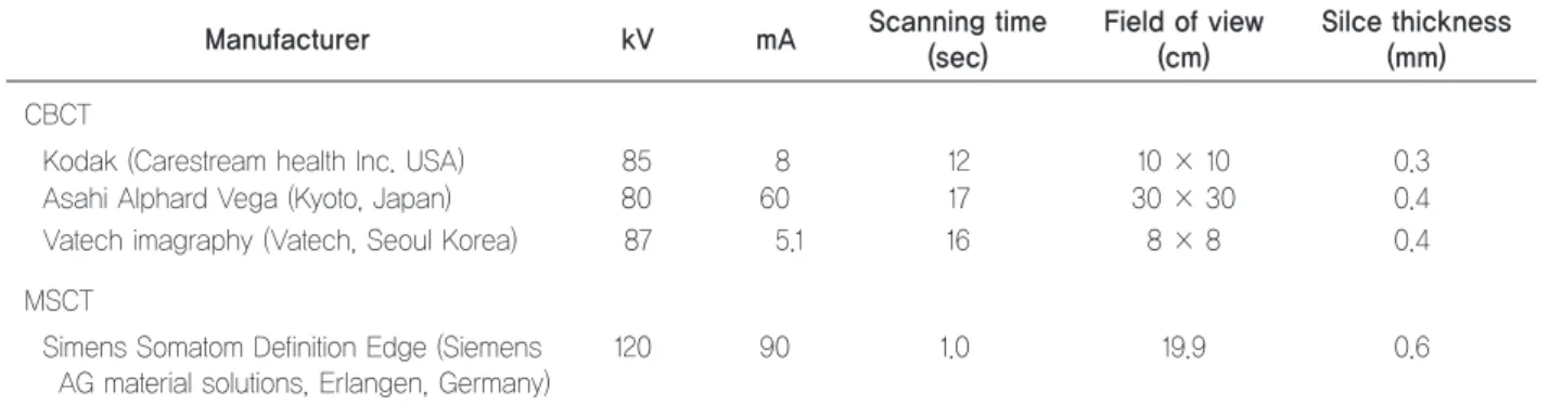
Table 1. Overview of MSCT and 3 CBCT devices and scanning parameters
Manufacturer kV mA Scanning time
(sec)
Field of view (cm)
Silce thickness (mm) CBCT
Kodak (Carestream health Inc. USA) 85 8 12 10 × 10 0.3
Asahi Alphard Vega (Kyoto, Japan) 80 60 17 30 × 30 0.4
Vatech imagraphy (Vatech, Seoul Korea) 87 5.1 16 8 × 8 0.4
MSCT
S imens Somatom Definition Edge (Siemens AG material solutions, Erlangen, Germany)
120 90 1.0 19.9 0.6
MSCT: multi-slice computed tomography, CBCT: cone-beam computed tomography.
Figure 2. Reorientation and bone density measurement. A, In the coronal view, the line passing through the central fossa of the mandibular first molars on both sides was used as the reference line. B, In the sagittal view, the image was reoriented according to the radiopaque blue resin along the mandibular occlusal plane from the mandibular incisor tip to the mesial cusp of the mandibular first molar. Bone density was measured in the bone 3, 6, and 9 mm from the alveolar crest (directly below the blue resin between the second premolar and first molar). C, In the axial view, the image was reoriented so the interradicular line between the second premolar and first molar was perpendicular to the screen. D, Determination of bone density values with MSCT (HU) and CBCT (VV).
A B
C D
Bone Density Measurements: Multi-Slice Computed Tomography versus Cone-Beam Computed Tomography | Lee et al.
monk, NY, USA). When the significance between the two investigators and repeated measurements from each investigator were analyzed by t-tests, no significant differences were found in the mea- surements made by the two investigators (P>0.5).
Comparisons of bone density measurements from MSCT and CBCT were performed by t-tests. The level of statistical significance was set as P≤0.05.
Fitted lines were added to the scatter plot be- tween the gray scale (HU and VV) with MSCT and CBCT to calculate the coefficient of deter- mination (R2). A one-way analysis of variance (ANOVA) was performed, and Dunnett T3 post hoc analysis was used for multiple comparison of density measurements from images scanned with MSCT and CBCT through Invivo and Simplant software programs.
RESULTS
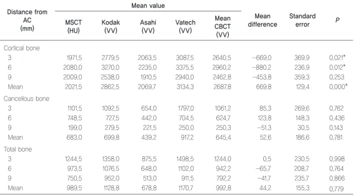
There was no statistical difference between right and left bone densities (Table 2). Mean cortical bone density values with MSCT and the CBCTs were significantly different, but mean cancellous and total bone densities measured with MSCT and the CBCTs were not significantly different (Table 3). Cortical bone density values with the CBCTs were statistically higher than those with MSCT except for Asahi. Cortical bone densities between Kodak and Asahi, Asahi and Vatech also showed a significant difference (Table 4).
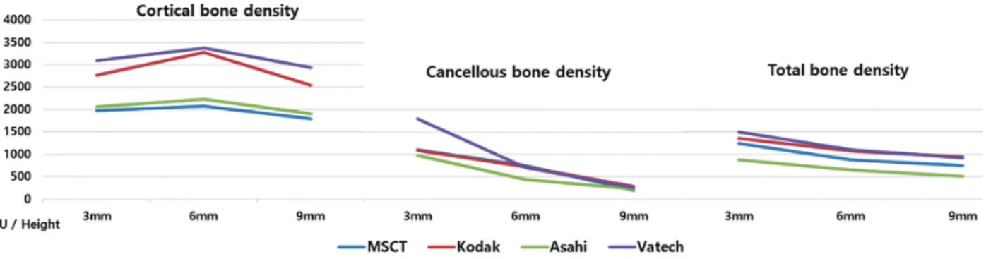
Cortical bone density was greatest at the height of 6 mm apically from the alveolar crest. Although the bone density values were different, a similar tendency was observed with MSCT and all CBCT images. Vatech showed the highest bone densi- ty values which were similar to Kodak. MSCT
Figure 3. The cortical, cancellous and total bone density values (HU, VV) at each height of the alveolar bone according to the scanners.
Table 2. Mean differences between right and left bone density values Bone density difference
(right-left) Mean SD 95% confidence interval
Lower limit Upper limit P
Cortical bone -7.33 237.98 -257.07 242.41 0.943
Cancellous bone -51.50 124.40 -182.05 79.06 0.357
Total bone -87.33 229.81 -528.50 -46.16 0.058
t-tests were performed; *P<0.05.
MSCT: multi-slice computed tomography, CBCT: cone-beam computed tomography.
6
Clin J Korean Assoc Orthod 2021;11(1):1-10
Table 3. Mean differences between MSCT and CBCT density values
Distance from AC (mm)
Mean value
Mean difference
Standard
error P
MSCT (HU)
Kodak (VV)
Asahi (VV)
Vatech (VV)
Mean CBCT (VV) Cortical bone
3 1971.5 2779.5 2063.5 3087.5 2640.5 -669.0 369.9 0.021*
6 2080.0 3270.0 2235.0 3375.5 2960.2 -880.2 236.9 0.012*
9 2009.0 2538.0 1910.5 2940.0 2462.8 -453.8 359.3 0.253
Mean 2021.5 2862.5 2069.7 3134.3 2687.8 669.8 129.4 0.000*
Cancellous bone
3 1101.5 1092.5 654.0 1797.0 1061.2 85.3 269.6 0.762
6 748.5 727.5 442.0 704.5 624.7 123.8 148.3 0.436
9 199.0 279.5 221.5 250.0 250.3 -51.3 30.5 0.143
Mean 683.0 699.8 439.2 917.2 645.4 52.6 186.6 0.781
Total bone
3 1244.5 1358.0 875.5 1498.5 1244.0 0.5 230.5 0.998
6 973.5 1076.5 648.0 1102.0 942.2 -65.7 208.7 0.764
9 750.5 952.0 513.0 911.5 792.2 -41.7 235.7 0.866
Mean 989.5 1128.8 678.8 1170.7 992.8 44.2 155.3 0.779
t-tests were performed; *P<0.05.
MSCT: multi-slice computed tomography, CBCT: cone-beam computed tomography, AC: alveolar crest, HU: Hounsfield unit, VV: voxel value.
Table 4. Statistical significance between MSCT and CBCT density values
Cortical bone Height (mm) Pa Pb Pc
MSCT
Kodak 3 0.063 0.939 0.034*
6 0.003* 0.924 0.425
9 0.012* 0.240 0.563
Asahi 3 0.580 0.243 0.239
6 0.165 0.297 0.311
9 0.521 0.657 0.559
Vatech 3 0.007* 0.942 0.258
6 0.006* 0.844 0.265
9 0.025* 0.349 0.467
Kodak
Asahi 3 0.098 0.305 0.048*
6 0.004* 0.102 0.177
9 0.046* 0.165 0.297
Vatech 3 0.279 0.930 0.009*
6 0.394 0.449 0.159
9 0.130 0.353 0.258
Asahi
Vatech 3 0.020* 0.586 0.432
6 0.008* 0.124 0.844
9 0.035* 0.135 0.755
t-tests were performed; *P<0.05.
Pa: cortical bone, Pb: cancellous bone, Pc: total bone.
MSCT: multi-slice computed tomography, CBCT: cone-beam computed tomography, Height: distance from alveolar crest.
Bone Density Measurements: Multi-Slice Computed Tomography versus Cone-Beam Computed Tomography | Lee et al.
showed the lowest bone density values which were similar in a statistically significant manner (Fig- ure 3). Cancellous bone density values with the CBCTs were different from those with MSCT but with no statistical significance. The cancellous bone density did not show any significant differ- ence between scanners (Table 4).
Cancellous and cortical bone densities decreased incrementally from alveolar crest to root apex, a tendency that was seen with all scanners. Vatech showed the greatest bone density at a height of 3 mm apically from the alveolar crest, but it de- creased closer to the root apex. Asahi showed the lowest bone density values while Kodak showed similar bone densities to those with MSCT (Fig- ure 3). The total bone density values with MSCT and Kodak, Kodak and Asahi, Kodak and Vatech showed a significant difference at a point 3 mm from the alveolar crest (Table 4). Total bone densi- ty decreased incrementally from alveolar crest to root apex. A similar tendency was observed with all scanners (Figure 3).
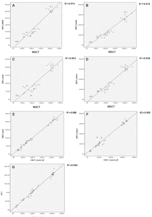
The R2 of the mean bone densities with the CBCTs and MSCT was 0.914. Compared to MSCT, the R2 values with Kodak, Asahi, and Vat- ech were 0.916, 0.854 and 0.928, respectively. The R2 values for measurements performed after a 90°
rotation of the dry mandible were 0.988 with Asa- hi and 0.950 with Vatech. They showed a linear relationship between the MSCT and CBCT bone density values (Figure 4A-D). The dry mandible was rotated by 90° and scanned using Asahi and Vatech, and the bone densities derived from the 2 CBCTs were compared (Figure 4E, F). Bone den- sity measurements were made with MSCT using 2 software programs (Invivo and Simplant) that demonstrated that there were no significant differ- ences between them (Figure 4G).
DISCUSSION
Bone density evaluations are useful for various dental procedures such as placing dental implants and orthodontic microimplants and for monitoring the rate of tooth movement. The information is al- so useful to diagnose tooth ankylosis, periodontal and endodontic lesions, and to predict growth pat- terns and potential. MSCT is absolutely the prop- er tool for measuring bone density, but it is not be commonly used in dentistry because of its high cost and high radiation dosage. Conversely, CBCT is popular in dentistry because of the relatively low dose of radiation exposure, short measure- ment time, low cost, and relatively high resolution of the resulting images.1-3
Researchers have assumed that measuring bone density with CBCT images was an unreliable and non-reproducible process because the results var- ied not only within the same object and the same machine8,12 but also according to the devices,8,13 object position,8,13,14 software types,15 and presence of artifacts.16 However, in this study, when the dry mandible was re-scanned after 90° rotation with Asahi and Vatech scanners, there was no signif- icant difference between the original scan and a scan after the 90° rotation (R2=0.988, 0.950).
It is difficult to make a direct comparison of gray density values obtained from different CBCTs.
Compared to MSCT, the attenuation coefficient with CBCT has not been standardized. The gray density values between CBCT scanners are influ- enced by technical factors such as the X-ray beam hardening effect, radiation scatter, and effects as- sociated with projection data discontinuity.5,17 However, according to Cassetta et al.,18 there is a linear relationship between gray density values and true attenuation coefficients on reconstructed CBCT images. If these equations are connected through bone density ratios for gray density val-
8
Clin J Korean Assoc Orthod 2021;11(1):1-10
Figure 4. Linear regression results. A, Relationship between the mean CBCT and MSCT gray scales (R2=0.914). B, Relationship be- tween Kodak and MSCT gray scales (R2=0.916). C, Relationship between Asahi CBCT and MSCT gray scales (R2=0.854). D, Rela- tionship between Vatech and MSCT gray scales (R2=0.928). E, Relationship of the Asahi gray scales (R2=0.998) with the dry mandi- ble in the original position and rotated 90°. F, Relationship of the Vatech gray scales (R2=0.950) with the dry mandible in the original position and rotated 90°. G, Relationship between the measurement with different software programs (Invivo and Simplant, R2=0.904).
A
C
E
G
B
D
F
Bone Density Measurements: Multi-Slice Computed Tomography versus Cone-Beam Computed Tomography | Lee et al.
ues that are reoriented and measured individually, the influences of the machine and environment get removed, leaving only the attenuation coefficient.
This indicates that the bone density ratio would be similar to the ratio of absolute values and that comparisons can be made with different scanners and scanning conditions.
On average, VV measured with CBCT is known to be greater than HU measured with MSCT.19 This could be the result of the X-ray beam harden- ing effect. In this study, the VV from the CBCTs was higher despite the differences between the machines. These differences were more promi- nent in the cortical bone density.
Arisan et al.20 reported that the beam hardening effect increases when radiation impermeability in- creases. Therefore, although VV and HU clearly differed in cortical bone, the values were similar in the low density maxillary cancellous bone.21 However, gray density values with MSCT and CBCT showed a strong correlation during experi- ments conducted on cadavers. Cassetta et al.18 did not observe any differences between cancellous and cortical bone in terms of bone density. In the present study, the differences between machines increased with increasing bone density as report- ed by Arisan et al.20 and Mori et al.21 In contrast, practically no difference was observed in cancel- lous bone, since the differences between machines decreased with decreasing bone density.
Gray scales are not the same from one machine to the next because, in part, CBCT manufactur- ers have not provided any standardized system for gray scale. Nackaerts et al.8 reported that the in- tensity values of 5 CBCT scanners varied from one device to the next. Even though an identical point from an identical subject was used for mea- surement in this study, different values were ob- tained from each of the CBCT scanners. Absolute values were highest with Vatech, followed by Ko-
dak and Asahi. Therefore, a direct comparison of bone density measurements with different CBCT scanners would be meaningless data. However, since scanners show similar tendencies in bone density measurements, relative density measure- ments from the various scanners can be used for comparison.
It is important to remember that there are ma- ny contributing factors when making bone density measurements with CBCT such as the machine’s mechanical model year, the presence of soft tis- sue, and machine settings. These factors seem to be limitations in this study. To overcome them, we suggest that further studies should be conducted to see if equations can be calculated for each CBCT machine.
CONCLUSION
First, there is a linear relationship between HU measured with MSCT and VV measured with CBCT. Second, although absolute values cannot be produced when measuring bone density with CBCT, relative values can be compared when us- ing identical CBCT scanners. Third, cortical bone density was significantly different depending on the basis of the measurements, but cancellous and total bone densities were essentially the same with MSCT and CBCT. Fourth, the positional setting of the dry mandible and different software program did not influence the bone density values.
REFERENCES
1. White SC, Pharoah, Micheal J. Oral radiology: Princi- ples and Interpretation. 6th ed. St Louis: Mosby; 2009, p. 235-236.
2. Lee MY, Park JH, Kim SC, Kang KH, Cho JH, Cho JW, Chang NY, Chae JM. Bone density effects on the suc- cess rate of orthodontic microimplants evaluated with cone-beam computed tomography. Am J Orthod Dento-
10
Clin J Korean Assoc Orthod 2021;11(1):1-10
facial Orthop 2016;149:217-224.
3. Jung YR, Kim SC, Kang KH, Cho JH, Lee EH, Chang NY, Chae JM. Placement angle effects on the success rate of orthodontic microimplants and other factors with cone-beam computed tomography. Am J Orthod Dento- facial Orthop 2013;143:173-181.
4. Mah P, Reeves TE, McDavid WD. Deriving Hounsfield units using grey levels in cone beam computed tomog- raphy. Dentomaxillofac Radiol 2010;39:323-335.
5. Pauwels R, Jacobs R, Singer SR, Mupparapu M. CBCT- based bone quality assessment: are Hounsfield units ap- plicable? Dentomaxillofac Radiol 2015;44:20140238.
6. Ribeiro-Rotta RF, Pereira AC, Oliveira GH, Freire MC, Leles CR, Lindh C. An exploratory survey of diagnostic methods for bone quality assessment used by Brazilian dental implant specialists. J Oral Rehabil 2010;37:698- 703.
7. Lekholm U, Zarb GA. Patient selection and preparation.
In: Branemark PI, Zarb GA, Albrektsson T, editors. Tis- sue integrated prosthesis; osseointegration in clinical dentistry. Chicago: Quintessence; 1985, p. 199-209.
8. Nackaerts O, Maes F, Yan H, Couto Souza P, Pauwels R, Jacobs R. Analysis of intensity variability in multislice and cone beam computed tomography. Clin Oral Im- plants Res 2011;22:873-879.
9. Valiyaparambil JV, Yamany I, Ortiz D, Shafer DM, Pendrys D, Freilich M, Mallya SM. Bone quality evalu- ation: comparison of cone beam computed tomography and subjective surgical assessment. Int J Oral Maxillo- fac Implants 2012;27:1271-1277.
10. Razi T, Niknami M, Alavi Ghazani F. Relationship be- tween Hounsfield Unit in CT Scan and Gray Scale in CBCT. J Dent Res Dent Clin Dent Prospects 2014;8:107- 110.
11. Silva IM, Freitas DQ, Ambrosano GM, Bóscolo FN, Almeida SM. Bone density: comparative evaluation of Hounsfield units in multislice and cone-beam computed tomography. Braz Oral Res 2012;26:550-556.
12. Campos MJ, de Souza TS, Mota Júnior SL, Fraga MR, Vitral RW. Bone mineral density in cone beam comput- ed tomography: only a few shades of gray. World J Ra- diol 2014;6:607-612.
13. Katsumata A, Hirukawa A, Okumura S, Naitoh M, Fu- jishita M, Ariji E, Langlais RP. Effects of image arti-
facts on gray-value density in limited-volume cone- beam computerized tomography. Oral Surg Oral Med Oral Pathol Oral Radiol Endod 2007;104:829-836.
14. Lagravère MO, Carey J, Ben-Zvi M, Packota GV, Major PW. Effect of object location on the density measure- ment and Hounsfield conversion in a NewTom 3G cone beam computed tomography unit. Dentomaxillofac Ra- diol 2008;37:305-308.
15. Liu Y, Bäuerle T, Pan L, Dimitrakopoulou-Strauss A, Strauss LG, Heiss C, Schnettler R, Semmler W, Cao L. Calibration of cone beam CT using relative attenu- ation ratio for quantitative assessment of bone density:
a small animal study. Int J Comput Assist Radiol Surg 2013;8:733-739.
16. Molteni R. Prospects and challenges of rendering tissue density in Hounsfield units for cone beam computed to- mography. Oral Surg Oral Med Oral Pathol Oral Radiol 2013;116:105-119.
17. Lagravère MO, Fang Y, Carey J, Toogood RW, Packota GV, Major PW. Density conversion factor determined using a cone-beam computed tomography unit NewTom QR-DVT 9000. Dentomaxillofac Radiol 2006;35:407- 709.
18. Cassetta M, Stefanelli LV, Pacifici A, Pacifici L, Barba- to E. How accurate is CBCT in measuring bone density?
A comparative CBCT-CT in vitro study. Clin Implant Dent Relat Res 2014;16:471-478.
19. Naitoh M, Hirukawa A, Katsumata A, Ariji E. Evalua- tion of voxel values in mandibular cancellous bone: re- lationship between cone-beam computed tomography and multislice helical computed tomography. Clin Oral Implants Res 2009;20:503-506.
20. Arisan V, Karabuda ZC, Avsever H, Özdemir T. Con- ventional multi-slice computed tomography (CT) and cone-beam CT (CBCT) for computer-assisted implant placement. Part I: relationship of radiographic gray den- sity and implant stability. Clin Implant Dent Relat Res 2013;15:893-906.
21. Mori S, Endo M, Tsunoo T, Kandatsu S, Tanada S, Aradate H, Saito Y, Miyazaki H, Satoh K, Matsushi- ta S, Kusakabe M. Physical performance evaluation of a 256-slice CT-scanner for four-dimensional imaging.
Med Phys 2004;31:1348-1356.
pISSN 2733-6026 / eISSN 2384-1230 Clin J Korean Assoc Orthod 2021;11(1):11-21 https://doi.org/10.33777/cjkao.2021.11.1.11
Dr. 김 경 아 Dr. 김 수 정
Dr. 안 효 원 Dr. 안 성 재
Corresponding author: Kyung-A Kim Department of Orthodontics, School of Dentistry, Kyung Hee University,
23 Kyungheedae-ro, Dongdaemun-gu, Seoul 02447, Korea Tel: +82-2-958-9390 E-mail: [email protected] Received: November 7, 2020 / Revised: December 5, 2020 / Accepted: December 6, 2020
ABSTRACT
Mouth breathing is accompanied by functional problems, such as lip insufficiency, low tongue posture and decreased masticatory muscle activity. If the oral environment is out of balance due to mouth breathing, craniofacial deformities become severe. Therefore, it is becoming important to differentiate and diagnose the cause of problems accurately and to break the relationship between mouth breathing and skeleton by determining the appropriate timing and method of intervention. In this case report, skeletal Class II growing patient with mouth breathing was treated with growth modification by the combination of adenotonsillectomy, myofunctional therapy and functional appliance. As a result, changes in the way of breathing and position of tongue during the facial growth had a positive effect on the improvement of mandible growth direction. (Clin J Korean Assoc Orthod 2021;11(1):11-21)
Key words Mouth breathing, Growth modification, Adenotonsillectomy, Myofunctional therapy
구호흡을 가진 성장기 골격성 II급 부정교합 환자에서
편도/아데노이드 절제술과 구강근기능요법을 동반한 성장 조절 치험례
안성재, 안효원, 김수정, 김경아
경희대학교 치과대학 치의학전문대학원 치과교정학교실
Growth Modification Treatment of Skeletal Class II Growing Patient with Mouth Breathing Using Adenotonsillectomy and Myofunctional Therapy
Sung-Jea Ahn, Hyo-Won Ahn, Su-jung Kim, Kyung-A Kim Department of Orthodontics, School of Dentistry, Kyung Hee University, Seoul, Korea
CASE REPORT
12
Clin J Korean Assoc Orthod 2021;11(1):11-21
서론
진료실에 내원하는 성장기 부정교합 환자의 경우 치 아의 배열 및 악골 간의 구조적인 문제뿐만 아니라 구호 흡과 같은 기능적인 문제를 함께 가지고 내원하는 경우 를 종종 볼 수 있다. 이러한 구호흡은 입술 부전, 저위 설, 저작근 활성 감소 등의 기능 문제들을 수반하게 되 며 힘의 균형이 깨짐에 따라 악안면 골격 변형을 심화 시킨다. 이처럼 기능적인 문제가 악골의 부조화를 더욱 심화시킬 수 있으므로 중요 문제의 원인을 정확히 감별 진단하고, 알맞은 치료 시작 시기와 알맞은 치료법을 결정하여 이러한 관계를 차단하는 것이 무엇보다 중요 해지고 있다.
본 증례 보고에서는 구개편도 비대와 혀의 저위로 인 한 구호흡을 가진 성장기 골격성 II급 부정교합 환자에
서 아데노이드편도절제술(adenotonsillectomy), 구강 근기능요법과 기능성 장치를 동반한 성장 조절 증례를 제시하고자 한다.
진단
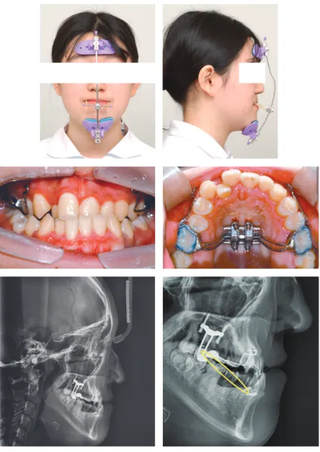
10세 9개월의 남자 환자가 구호흡과 입술을 다물지 못한다는 주소로 내원하였다. 초진 시 정면 안면 사진 에서 동공간선을 기준으로 비대칭은 나타나지 않았으 며, 안정위 시 입술을 완전히 다물지 못하여 전치의 치 관이 노출되었다. 측면 안면 사진에서 작은 비순각과 상순의 돌출을 나타내었다. 구내 사진에서 II급 구치 관 계, 전치부 과개교합, 큰 수평피개, 깊은 스피 만곡, 하 악 전치부의 크라우딩을 관찰할 수 있었다(Figure 1).
측면 두부계측방사선사진 분석에서 골격성 II급
Figure 1. Pretreatment facial photographs (A) and intraoral photographs (B).
A
B
Growth Modification Treatment of Skeletal Class II Growing Patient Using Adenotonsillectomy and Myofunctional Therapy | Ahn et al.
(SNA: 75.7°, SNB: 72.7°, ANB: 3°, APDI: 79°)과 단 안모 안면 고경 양상[Bj¨ork sum: 394.3°, Frankfort mandibular plane angle (FMA): 20.5°]을 관찰할 수 있었다. 상악 전치는 정상 각도를 보이며(U1 to FH:
118.4°), 하악 전치의 경사는 약간의 순측 경사를 보였 다[L1 to mandibular plane (IMPA): 103°]. 또한 연 조직 측면에서는 아데노이드와 편도의 비대와 저위된 혀가 관찰되었다(Figure 2).
치료계획
치료목표는 (1) 구호흡을 개선하여 올바른 방향으로 악안면 성장을 유도하고, (2) 구강근기능요법을 통하여 습관을 조절하고, (3) 상·하악골의 부조화를 해소하는 것이다.
먼저, 비호흡이 가능하도록 아데노이드편도절제술 (adenotonsillectomy)을 통해 기도를 막고 있는 비대 한 림프조직을 제거하고, 구강근기능요법을 통하여 비 호흡을 인지시키고 습관화하도록 계획하였다. 이후 경 부 견인 헤드기어(cervical pull headgear)를 통한 상 악 원심 이동을 계획하였다. 하악은 제1대구치의 후
기 근심 이동을 억제하면서 유구치의 근심면을 삭제하 는 방법(mesial stripping method)을 통해 하악 치 열의 크라우딩을 해결하도록 하였으며, 기능성 장치 (functional appliance)를 사용하여 하악의 성장을 유 도하며 악골의 부조화를 줄이고자 계획하였다. 1차 치 료 이후, 환자의 상태를 재평가하여 고정식 교정장치를 이용한 전악 배열을 결정하기로 하였다.
치료경과 및 결과
치료경과
초진 시 관찰된 편도의 비대 및 기도의 폐쇄와 그로 인한 구호흡, 하악의 후퇴를 막기 위해 이비인후과를 방문하여 아데노이드편도절제술(adenotonsillectomy) 을 우선적으로 실시하였다.
그 이후 경부 견인 헤드기어를 적용하고, 하루의 절 반 이상(12~14시간) 착용하도록 하여 상악의 원심 이 동을 진행하였다. 6개월 뒤 액티베이터를 함께 사용하 여 하악을 지속적으로 전방에 위치하도록 하고, 전치부 토킹 스프링(torquing spring)을 첨가하여 전치부 설 측 경사를 방지하였다. 주변 근육이 새로운 위치에 적
Figure 2. Pretreatment lateral cephalogram (A) and panoramic radiograph (B).
A B
14
Clin J Korean Assoc Orthod 2021;11(1):11-21
응하게 하며, 외측익돌근이 원판 후방부의 활성을 증가 시켜 하악 과두의 성장을 촉진하도록 하였으며, 기능성 장치의 선택적 삭제를 통해 I급 구치부 관계를 유도하였 다. 성장 조절 치료 도중 기도를 막는 해부학적인 요인 들은 제거되었지만, 계속해서 저위되어 있는 혀와 개방 된 입술이 측면 두부계측방사선사진을 통해 관찰되었 다(Figure 3). 이를 해소하기 위하여 입술 폐쇄를 위한 구륜근 훈련(윗입술 당기기, 버튼 물기, 아에우 훈련), 비호흡을 인식할 수 있도록 하는 훈련(구호흡/비호흡 구 별, 좌우 비호흡 훈련, 비호흡과 구륜근 훈련 같이하 기), 혀의 거상 훈련을 포함한 구강근기능요법을 지속하 여 실행하였다(Figure 4). 총 1년 4개월간 헤드기어 및 액티베이터 장치의 사용 결과, 환자의 협조도 덕분에 안
모와 수평피개의 개선을 얻을 수 있었고, 교합관계도 I 급 구치 관계를 달성하여 많은 개선을 보여주었다. 지속 적인 구강근기능요법을 통한 입술 및 혀의 위치 개선도 나타났다(Figures 5, 6).
이후 남아있는 크라우딩을 해소하기 위해 고정식 교 정장치를 부착하여 배열을 시작하였다. 원형 Cupper- NiTi 와이어(0.014-inch to 0.018-inch)로 초기 배열 및 레벨링을 진행하면서 하악 전치부 치간 삭제(inter proximal reduction)를 동반하여 전치부 크라우딩을 해소하였다. 각형 스테인리스 강 와이어(상악: 0.017 × 0.025-inch; 하악: 0.016 × 0.022-inch)를 브라켓 (0.022-inch 슬롯)에 삽입하여 마무리 과정을 진행하 였다(Figures 7, 8).
Figure 3. Pretreatment lateral photograph and cephalogram (A), after adenotonsillectomy (A&T) and 10-month growth modification (G/M) lateral photograph and cephalogram (B), superimposition of pretreatment (black) and after A&T and 10 month G/M (red) ceph- alometric tracings (C).
A B C
Growth Modification Treatment of Skeletal Class II Growing Patient Using Adenotonsillectomy and Myofunctional Therapy | Ahn et al.
Figure 4. Myofunctional therapy (MFT) for training lip competence (A), nasal breathing (B), and tongue elevation (C).
Lip pull
Button pull
/ah/, /eh/, /ooh/ exercises Popping
Distinguish between nasal and mouth breathing
Right, left nasal breathing
Nasal breathing + Lip competence
Tongue elevation
Tongue elevation C, Tongue exercises B, Nasal breathing exercises
A, Lip competence exercises
A
B
16
Clin J Korean Assoc Orthod 2021;11(1):11-21
Figure 6. Midtreatment lateral cephalogram (A) and panoramic radiograph (B).
A B
Figure 7. Posttreatment facial photographs (A) and intraoral photographs (B).
A
B
Growth Modification Treatment of Skeletal Class II Growing Patient Using Adenotonsillectomy and Myofunctional Therapy | Ahn et al.
결과
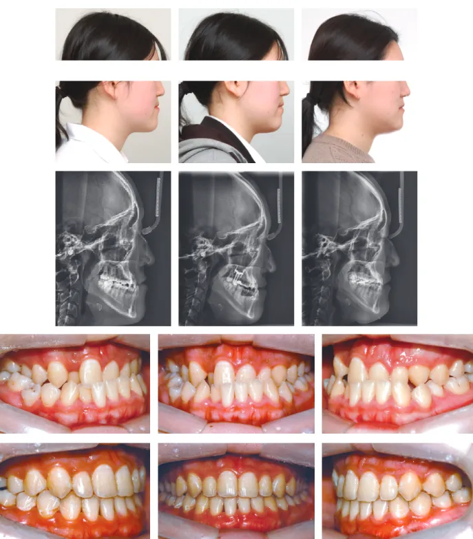
치료 후 구내 사진에서 양측 모두 I급 구치부 관계와 적절한 수직피개 및 수평피개, 정중선 일치를 보이고 있 다. 안모에서도 하악의 전방성장으로 인한 자연스러운 입술의 폐쇄가 나타나고 입술 돌출감이 해소된 것을 볼 수 있다(Figure 9).
치료 전후 측면 두부계측방사선사진을 중첩한 결과 아데노이드 및 편도의 제거로 기도장애물 제거 및 기 도의 확장을 관찰할 수 있고, 구강근기능요법을 지속한 결과, 혀 위치의 거상과 입술의 폐쇄가 가능해진 것을 확인할 수 있다. 또한 하악골을 전방 이동시켜주는 액 티베이터의 착용으로 양호한 방향으로의 하악 성장 패 턴을 보여주었다(Figure 9).
계측결과 SNA값도 미약하게 증가(75.7˚→76˚)하였 지만, 하악의 전방 성장에 따라 SNB값이 현저하게 증 가(72.7˚→75.5˚)하면서 악간 관계가 좀 더 양호한 I급 관계로 변하였다(APDI: 79˚→85˚)(Tables 1 and 2).
고찰
구호흡은 입술 부전, 저위설, 저작근 활성 감소 등의 기능 문제들을 수반하게 되며 힘의 균형이 깨짐에 따라
악안면 골격 변형을 심화시킨다. 또한 치료를 통해 골격 및 구강 구조가 개선된다 할지라도 입술 및 혀의 위치 가 개선되지 않는다면 호흡 기능의 실질적 개선으로 이 어지지 않게 된다. 구호흡을 제거하고 비호흡이 가능하 도록 해부학적 구조에 대한 치료가 우선 진행되어야 하 지만, 동시에 적극적인 구강근기능요법을 통해 구강계 힘의 균형을 회복시켜 주는 것도 중요하다.
구호흡의 발생 원인은 폐쇄성(obstructive), 습관성 (habitual), 해부학적(anatomical)의 3가지 원인이 있 으며, 이러한 원인들로 인한 만성 구호흡은 악안면 성 장을 저해하여 ‘아데노이드형 얼굴(adenoid face)’로 지 칭되는 특징적인 얼굴 형태로 변화하게 한다.1-3 편도 및 아데노이드 비대와 비염과 같은 상기도 공간의 물리적 인 폐쇄로 인하여 비강으로의 호흡이 어려워 발생하는 구호흡의 치료방법은 외과적인 방법으로, 아데노이드편 도절제술(adenotonsillectomy)이 있다.4,5
편도선은 소아기에 급격하게 발달하다가 성장이 진행 되면서 퇴화하는 기관이다. 따라서 평균적으로 10세 정 도까지의 편도 및 아데노이드 비대는 임상 증상이 없는 한 특별한 질환이라고 할 수는 없다. 하지만 성장의 관 점에서 보았을 때는 편도와 아데노이드가 비대되어 있 는 시기 동안에 나타나는 구호흡과 그로 인하여 좋지 Figure 8. Posttreatment lateral cephalogram (A) and panoramic radiograph (B).
A B
18
Clin J Korean Assoc Orthod 2021;11(1):11-21
Figure 9. After adenotonsillectomy (A&T) and 10-month growth modification (G/M) lateral photograph and cephalogram (A), midtreat- ment lateral photograph and cephalogram (B), posttreatment lateral photograph and cephalogram (C), superimposition of after A&T and 10 month G/M (Black), midtreatment (green), posttreatment (red) cephalometric tracings (D).
D
A B C
Growth Modification Treatment of Skeletal Class II Growing Patient Using Adenotonsillectomy and Myofunctional Therapy | Ahn et al.
못한 안면 성장 방향을 나타낼 것으로 예상되는 환자 의 경우에는 이를 개선하기 위한 아데노이드편도절제술 (adenotonsillectomy)이 적극적으로 필요하다고 볼 수 있다. 본 증례에서도 초진 시 관찰된 비대한 아데노이 드와 림프를 제거하여 비강의 폐쇄로 인한 구호흡이 발 생하지 않도록 하였다.
습관성 구호흡은 구조적으로 비강 호흡에 전혀 문제 가 없음에도 단순히 구호흡이 편하다는 이유로 구호흡
을 하는 것을 말한다. 비강의 폐쇄가 해소된 경우에도 약화된 구강주위근육을 강화하지 않으면 구호흡은 저 절로 개선되지 않는 경우가 있다. 따라서 습관성 구호 흡을 개선시키기 위해서 습관 교정장치 및 구강근기능 요법이 필요하다.6,7
본 증례에서도 아데노이드편도절제술(adenoton- sillectomy)을 실시한 이후 내원하였을 때, 상기도를 막는 해부학적인 요인들은 제거되었지만 계속해서 저위 Table 1. Comparison of cephalometric measurements
Measurement Norm Pretreatment After A&T
Cranio-facial
MxUL (mm) 99.8 91.7 92.0
MdUL (mm) 134.3 115.5 121.0
SNA (°) 81.3 75.7 75.0
SNB (°) 79.8 72.7 73.0
ANB (°) 1.5 3.0 2.0
APDI (°) 87.0 79.0 82.0
MPA (°) 23.8 21.0 23.0
LFH/TFH 50.0 51.9 57.0
PFH/AFH 70.0 64.3 63.0
Overjet (mm) 2.6 5.0 3.0
U6-FH (mm) 50.0 47.0 50.0
Tongue
TGL (mm) 75.1 74.0 77.0
TGH (mm) 38.0 29.0 34.0
Soft palate
SPL (mm) 36.0 31.0 40.0
SPT (mm) 10.0 10.0 11.0
SPI (°) 116.0 141.0 132.0
Airway
PNS-ad1 (mm) 23.0 19.0 25.0
PNS-ad2 (mm) 21.0 15.0 24.0
SPAS (mm) 12.0 11.0 10.0
MAS (mm) 11.0 8.0 11.0
IAS (mm) 10.0 3.0 9.0
OAW (mm) 10.0 8.0 9.0
VAL (mm) 78.4 58.0 66.0
Hyoid
MPH (mm) 20.1 6.0 11.0
H-C3RGN (mm) 3.4 3.0 2.0
H-RGN (mm) 37.8 31.0 39.0
H-C3 (mm) 42.7 33.0 38.0
H-C3Me (mm) 2.4 3.0 4.0
A&T: adenotonsillectomy, TGL: tongue length, TGH: tongue height, SPL: soft palate length, SPT: soft palate thickness, SPA: soft palate angle, SPAS: superior posterior airway space, MAS: middle airway space, IAS: inferior airway space, OAW: occlusal plane airway, VAL: vertical airway, MPH: mandibular plane to hyoid.