Ⅰ. INTRODUCTION
The loss of hard tissue in the cervical region of the tooth is a common clinical occurrence1). These noncarious cervical lesions (NCCLs) can occur on facial, lingual and/or interproximal surfaces.
Effects of occlusal load on the cervical stress distribution:
A three-dimensional finite element study
Hyeong-Mo Lee1, Bock Hur1, Hyeon-Cheol Kim1, Sung-Gwan Woo2, Kwang-Hoon Kim2, Kwon Son2, Jeong-Kil Park1*
1Department of Conservative dentistry, College of Dentistry, Pusan National University
2Department of Mechanical design engineering, College of Engineering, Pusan National University
The objective of this study was to investigate the effects of various occlusal loads on the stress distribu- tion of the buccal cervical region of a normal maxillary second premolar, using a three dimensional finite element analysis (3D FEA).
After 3D FE modeling of maxillary second premolar, a static load of 500N of three load cases was applied.
Stress analysis was performed using ANSYS (Swanson Analysis Systems, Inc., Houston, USA). The maxi- mum principal stresses and minimum principal stresses were sampled at thirteen nodal points in the buc- cal cervical enamel for each four horizontal planes, 1.0 ㎜ above CEJ, 0.5 ㎜ above CEJ, CEJ, 0.5 ㎜ under CEJ.
The results were as follows
1. The peak stress was seen at the cervical enamel surface of the mesiobuccal line angle area, asymmetri- cally.
2. The values of compressive stresses were within the range of the failure stress of enamel. But the val- ues of tensile stresses exceeded the range of the failure stress of enamel.
3. The tensile stresses from the perpendicular load at the buccal incline of palatal cusp may be shown to be the primary etiological factors of the NCCLs. [J Kor Acad Cons Dent 31(6):427-436, 2006]
Key words: Occlusal load, Stress distribution, Finite element analysis, Maxillary second premolar, Compressive stress, Tensile stress
- Received 2006.7.04., revised 2006.9.08., accepted 2006.9.13. - ABSTRACT
* Corresponding Author: Jeong-Kil Park Department of Conservative Dentistry
College of Dentistry, Pusan National University, 1-10, Ami-dong, Seo-gu, 602-739, Busan, Korea Tel: 82-51-240-7454
E-mail: [email protected]
Traditionally, this has been assumed to be due to the effects of abrasion and/or erosion1-3). More recently, an additional mechanism for cervical tooth loss with occlusal loading has been pro- posed2,4). Grippo3) has coined the term “abfraction”
to distinguish it from lesions caused by erosion and abrasion.
Clinically, there is some clinical evidence for the association of abfraction lesions with heavy occlusal loads. There is a marked association of these lesions with bruxism and malocclusion5). Some epidemiologic studies also reported a strong association between cervical lesions and occlusal tooth wear or occlusal erosion with 96% of teeth with a cervical lesion also having evidence of occlusal pathology6). These lesions have been shown in teeth subjected to lateral load, but adja- cent teeth that were not subjected to these forces remained unaffected7).
Abfraction lesions are sharp, angular, wedge- shaped defects that sometimes have a subgingival location and are often associated with occlusal wear facets7-9). These lesions are commonly obse- rved on the buccal and labial aspects of the teeth.
These lesions were rarely found on the lingual surface with one study reporting that only 2% of cervical lesions were found lingually6).
There is a gradually increasing body of evidence to suggest that the effects of occlusal loading con- tribute to the development of abfraction lesions.
This evidence comes from various types of stress and strain analysis including photoelastic stress analysis, strain gauge studies and finite element analysis (FEA).
Selna and co-workers10) revealed through 2D FEA that eccentric load application demonstrated internal stress distribution in the crown and roots, which may be interpreted as possible fail- ure planes both in the dental structures and restorations. Yettram and co-workers11) showed that the occlusal load on a mandibular second premolar flowed around enamel cap and through the thin enamel cervical area before being trans- mitted to the root in their 2D FEA. Goel et al.12) used the 3D FE model of the maxillary first pre-
molar. The magnitude of normal stresses increased at the cervical enamel and the normal stress and shear stress were markedly affected by the contour of the dentinoenamel junction (DEJ) and the thickness of the occlusal third on the buccal and lingual surfaces.
Palamara et al.13) used the model 3D FEA of a mandibular second premolar to investigate the effects of occlusal load on enamel surface. Point loads of 100N were applied axially at the 45。
from the vertical at the cusp. Strains predicted from the FEA model were in excellent agreement with the strain gauge measurements. Strains were concentrated near cementoenamel junction (CEJ) regardless of load direction. Rees14) devel- oped 2D FEA of a maxillary incisor, canine and first premolar and the cervical stress profiles were examined along a horizontal plane 1.1 ㎜ above the CEJ. The result of 500 N loaded 45。labioapi- cally to the incisal tip was that the stress profile in the cervical region of central incisor was greater than the canine or premolar. Tanaka et al.15)carried out stress analysis on the upper cen- tral incisor and the lower first molar using the plastic-elastic deformation theory with 2D FEA.
The result was that oblique loading causes plastic deformation near the CEJ. Geramy and Shara- foddin16)developed 3D FEA of a maxillary central incisor including periodontal ligaments and alveo- lar bone, which was loaded 1.5 N static non-axial and axial loads on the palatal side. The maximum displacement and stresses were shown at the cer- vical area on the non-axial load, but the axial load did not show the same.
In the previous study of 2D FEA, the results are unreliable for assessment of stress patterns due to its inability to duplicate tooth geometry.
Further refining the 3D FE model shape was important when analyzing the stress distribution within a tooth. The objective of this study was to investigate the effects of various occlusal loads on the stress distribution of the buccal cervical region of a normal maxillary second premolar, using a 3D FEA.
Ⅱ. MATERIALS AND METHODS Finite element model
For developing a 3D FE model to analyze, an intact normal extracted human maxillary second premolar was selected in this study. The premolar was scanned serially with Micro-CT (SkyScan 1072; SkyScan, Aartselaar, Belgium) to exposure the tooth sections perpendicular to the long axis of the tooth (58 ㎛ in thickness) and parallel to the occlusal plane. 3D-DOCTOR (Able Software Co., Lexington, MA, USA) image processing soft- ware was employed to detect the boundaries of enamel, dentin and pulp from the sectioned two dimensional images and to make a three-dimen- sional surface model. Rhino 3D (Robert McNeel &
Assoc., Seattle, WA, USA) was used to reduce useless nodes from the surface model and ANSYS (Swanson Analysis Systems, Inc., Houston, USA) was used to mesh.
The 3D FE model was consisted of hexahedral elements. The final model consisted of 15,608 ele- ments with 17,052 nodes. All the vital tissues were presumed linearly elastic, homogeneous and isotropic. The corresponding elastic properties such as Young's modulus and Poisson's ratio were determined according to literature survey (Table 1).
The periodontal ligament was assumed to be 0.3 ㎜ wide, and the dimensions of surrounding
compact and cancellous bone were derived from standard texts18,19). The alveolar bone was also generated by growing the outer surface of the tooth model from 2 ㎜ below the CEJ18,19). The pulp region was modeled as being hollow20). In these models, the outer surface of the alveolar bone model was fixed in order to prevent rigid body motion for FEA.
The model was fixed on mesiodistal direction. In all loading cases, the base nodes of simulated alveolar bone were assumed fixed to prevent rigid body motion.
Loading conditions
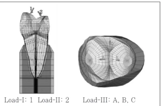
Static 500 N forces were applied for the follow- ing three loading conditions (Figure 1). The eccentric occlusion was simulated with two load- ing conditions. Load-I represented the perpendic- ular load at the point of upper third of palatal incline of buccal cusp. Load-II represented the perpendicular load at the point of upper third of buccal incline of palatal cusp. And the centric occlusion was simulated with Load-III. Load-III represent a unit load distributed at the three points corresponding to centric occlusion(A: per- pendicular load on the lower third of palatal slope of buccal cusp, B: perpendicular load on the buc- cal slope of palatal cusp, C: perpendicular load on the center of mesial marginal ridge).
Table 1. T Mechanical properties of the materials used in the study
Mechanical properties
Young's modulus (MPa) Poisson's ratio (υ)
Enamel 84000a 0.33a
Dentin 18000a 0.31a
PDL 0.667b 0.49b
Cancellous bone 13700b 0.38b Cortical bone 34000b 0.26b a : Katona et al.17) b : Geramy et al.16)
Materials
Figure 1. Three load conditions of 3D FE model.
Load-I: 1 Load-II: 2 Load-III: A, B, C
Stress analysis
Analysis of the principal stresses has been done by ANSYS.
The values of maximum and minimum principal stresses of thirteen nordal points in the buccal cervical region were sampled along four horizontal surface enamel planes (Level A, B, C, and D) and two horizontal DEJ planes (Level A, B). The Level of CEJ was designed as Level C and which was used as reference plane. Level A and B were the plane of 1.0 ㎜ and 0.5 ㎜ above the CEJ lev- el, respectively. And the Level D was 0.5 ㎜ below the CEJ.
Ⅲ. RESULTS Principal stress analysis
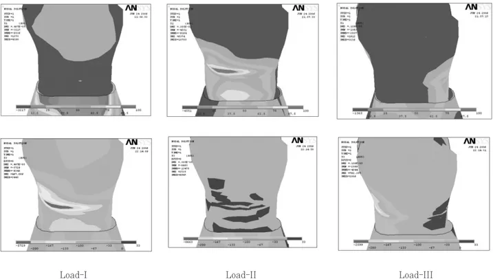
Cervical stress contours on the tooth surface in response to a static point 500 N load are shown in figure 2.
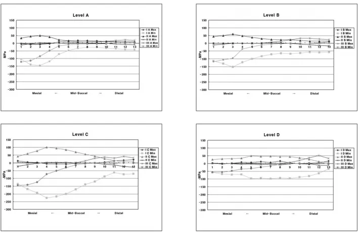
The principal stresses of Level A (Figure 3)
The principal stresses were different in magni- tude and character according to the load condi- tions.
In Load-I case, the peak tensile stress of 17 MPa at the mid-buccal and the peak compressive stress over the 144 MPa at the mesial side were observed. But in Load-II case, the peak tensile stress of 49 MPa was concentrated at the me- siobuccal line angle area. And in Load-III case, tensile stress of 21 MPa at the distal side and the peak compressive stress of 121 MPa at the mesial side were observed.
The principal stresses of Level B (Figure 3)
Peak compressive stress of 152 MPa was con- centrated at the mesiobuccal line angle area in Load-I case. And peak tensile stress of 59 MPa at the mesiobuccal line angle area in Load-II case.
In Load-III case, peak compressive stress of 118
Load-I Load-II Load-III
Figure 2. Principal stress distribution of Load-I,II,III
MPa at the mesiobuccal line angle and peak ten- sile stress of 32 MPa at the distobuccal line angle were detected.
The principal stresses of Level C (Figure 3)
In Load-I case, the peak tensile stress of 20 MPa at the distal side and the peak compressive stress over the 226 MPa at the mesiobuccal line
Table 2.Peak stresses of enamel surface of various levels and loading points
Load I Load II Load III
MPa Node MPa Node MPa Node
Max 17* 7 49* 3 21* 12
Min -144 3 NS NS -121 1
Max NS NS 59* 3 32* 11
Min -152 3 NS NS -118 1
Max 20* 13 101* 4 41* 12
Min -226 4 NS NS -144 1
Max 16* 8 49* 5 51* 12
Min -97 5 NS NS -55 1
*: Excessive stresses over the failure range, NS: Not significant Level A
Level B
Level C
Level D
Figure 3. Principal stresses of Level A,B,C,D of three load conditions.
angle area were observed. But in Load-II case, the peak tensile stress over the 101 MPa was concentrated at the mesiobuccal line angle area.
And in Load-III case, the tensile stress was par- ticularly observed between the mid-buccal and the distal CEJ. The peak tensile stress of 41 MPa at the distal CEJ and the peak compressive stress of 144 MPa at the mesial CEJ were observed.
The principal stresses of Level D (Figure 3)
In Load-I case, the peak tensile stress of 51 MPa at the distal root surface dentin and the peak compressive stress over the 97 MPa at the mesiobuccal line angle area were observed. But in Load-II case, the peak tensile stress of 49 MPa was observed at the mesiobuccal line angle area.
And in Load-III case, the peak tensile stress of 51 MPa at the distal root surface dentin and the peak compressive stress of 55 MPa at the mesial side were observed.
For the convenience of analyzing the overall stress distribution of enamel surface, the peak stresses of four levels according to load conditions were summarized in Table 2 and compared to mechanical properties of tooth structure (Table 3).
Ⅳ. DISCUSSION
The etiology of NCCLs has not been precisely defined. Most authorities agree that the cause is multifactorial and thus difficult to recognize22). The most frequent causes are erosion, abrasion and occlusal loading. Occlusal stresses are the
can produce cervical lesions23). When eccentric occlusal forces are applied to a tooth, both com- pressive and tensile stresses are placed on the structure. The stress produced causes the tooth to flex. This has been proposed as a tooth flexure theory by Levitch et al.24). The fulcrum of this bending movement and the place where eccentric occlusal forces are concentrated is the cervix of the tooth. The location of the fulcrum determines the exact site of the lesion24). A longitudinal case study25) of a person showed a direct correlation between occlusal wear and the growth of NCCLs.
Heymann et al.26) also found a relationship between the loss of cervical restorations and the presence of a traumatic occlusion, which is expected to cause more cuspal flexure.
In order to determine the load conditions such as magnitudes, directions, occlusal contacts (i.e., point or surface, centric or eccentric), preliminary investigation was performed using the data gath- ered by literature review27,28). Based upon these data, 170 N was assumed as the chewing force for premolars and 500 N was assumed as the heavy parafunctional load of bruxism and traumatic occlusion. In this study, a tooth model loaded by a point load of static 500 N was considered more representative of high-risk loading situation, in contrast to other FEA studies11-16). Load-I for buc- cal eccentric occlusion and Load-II for palatal eccentric occlusion were selected. Load-III was selected for mimicking the effect of a unit load in centric occlusion.
The peak stress was seen asymmetrically at the CEJ of mesiobuccal line angle area. The position of maximum stress concentration found in this study was different from previous studies29-32). This pattern of stress distribution may be related to the anatomical asymmetry. Palamara et al.13) reported that strains resulting from oblique loads on buccal cusp inclines were asymmetric.
The position of the peak stress found in this study was at the CEJ. Many studies11,13,15,16,29-31)
reported that the peak stress was concentrated at the CEJ in their FEA models. Kuroe et al.32) also confirmed by the photoelastic method that a ver- Table 3.Mechanical properties of teeth (MPa)*
Compressive strength of enamel 277 - 384 Compressive strength of dentin 249 - 347 Tensile strength of enamel 10 - 24 Tensile strength of dentin 32 - 103 Tensile strength of dentinoenamel 52
junction
* Litonjua et al.21)
centration at the cervical line.
Contrary to our results, Rees et al.4,14,33-35) pro- posed that the sampling horizontal planes were chosen at 1.1 ㎜ above the CEJ among the buccal cervical region because an initial pilot study showed this to be the position of maximum stress concentration. Despite their findings, the results of their study must be interpreted with a certain amount of caution. First, their analysis was a 2D FEA so it was not possible to model any small twisting movements of the tooth in the Z-axis direction. Second, their study modeled a bucco- lingual slice through the center of the tooth and therefore represents the worst possible case, since they assumed that teeth flex more in the middle.
They thought that a more mesially or distally placed slice would give less cuspal flexure and, presumably, lower cervical stresses. However, in our study, mesiobuccal line angle area was greater than mid-buccal area under 3D FEA model.
Several studies have shown that enamel and dentin are less resistant to tensile stress than compressive stress36-39). In compressive stress, enamel can withstand forces up to 35 times greater than when subjected to tensile stress;
meanwhile, dentin can resist compressive forces at least seven times greater than the amount of tensile stress that will cause it to fail37, 38). The tensile strengths of enamel and dentin are much lower than are their respective compre- ssive strengths38,39).
According to the experiment, tensile stress affected the result to the meaningful level while the effect of compressive stress was not. For in terms of Level A, B, C, and D, the peak compres- sive stress was under the failure stress of the enamel but the peak tensile stress observed 4 times as much as the failure stress of the enamel.
As the results of the evaluation of the principal stresses, it has been shown that the tensile stress on the buccal CEJ regions was dominant in the lesion initiation. This results are similar with Tanaka et al.15) which they reported that when the force was oblique, plastic deformation of the lower first molar appeared at the enamel surface
along the cervical region because of the tensile stress. Spears et al.40)showed that a vertical force loaded at one tip of the lingual cusp of the mandibular second premolar produces tensile stress at the lingual enamel on the cervical region. Borcic et al.31) reported that in their 3D FEA model, large tensile stress appeared on the enamel surface near the cervical line at the side opposite the loading point.
This study reports a strong association between loading forces of Load-II and the possibility of failure of enamel and dentin of the buccal cervical area by tensile stress -the same as other studi- es15,29,31). Since the tensile stress of Load-II was 101 MPa, the highest level on the CEJ, Load-II is thought to be the most damaging factor. Lee and Eakle7) also proposed that the primary etiologic factor in wedge-shaped cervical lesions is tensile stress from mastication and malocclusion, and that local factors may play a secondary role in the dissolution of tooth structure.
We adopted Load-III mimicking centric occlusion as control group in order to compare it with the eccentric occlusion. Unexpectedly, Load-III gener- ated tensile stress enough to destroy enamel on the distal CEJ. In these results, we came to con- clusion that tensile stress generated from the cen- tric occlusion may be related to the formation of NCCLs in a significant level. Not only eccentric occlusion but also centric occlusion seems to be related with the formation mechanism of NCCLs clinically observed in the buccal CEJ, the Level C, and they seems to generate stress concentra- tion working together.
Grippo41) said that the high incidence of cervical abfraction lesions in Koreans is noteworthy and warrants investigation in his suggestions for future studies. But it is hard to find the epidemi- ologic study reported a strong association with a NCCLs and occlusal tooth wear except for one Korean study42). It is necessary to have further clinical study for NCCLs of Koreans together with epidemiologic study and this study of 3D FEA using the maxillary second premolar of a Korean might be the preliminary research.
Ⅴ. CONCLUSIONS
1. The peak stress was seen at the cervical enam- el surface of the mesiobuccal line angle area, asymmetrically.
2. The values of compressive stresses were within the range of the failure stress of enamel. But the values of tensile stresses exceeded the range of the failure stress of enamel.
3. The tensile stresses from the perpendicular load at buccal incline of palatal cusp may be shown to be the primary etiological factors of the NCCLs.
REFERENCES
1. Rees JS. A review of the biomechanics of abfraction.
Eur J Prosthodont Restor Dent 8(4):139-144, 2000.
2. Lee WC, Eakle WS. Stress-induced cervical lesions:
Review of advances on the past 10 years. J Prosthet Dent 75:487-494, 1996.
3. Grippo JO. Abfractions: A new classification of hard tissue lesions of teeth. J Esthet Dent 3(1):14-19, 1991.
4. Rees JS, Hammadeh M. Undermining of enamel as a mechanism of abfraction lesion formation: A finite ele- ment study. Eur J Oral Sci 112:347-352, 2004.
5. Lambrechts P, Braem M, Vanherle G. Evaluation of clinical performance for poster composite resins and dentin adhesives.Oper Dent 12:53-78, 1987.
6. Khan F, Young WG, Shahabi S, Daley TJ. Dental cer- vical lesions associated with occlusal erosion and attri- tion. Aust Dent J 44:176-186, 1999.
7. Lee WC, Eakle WS. Possible role of the tensile stress in the etiology of cervical erosive lesions of teeth. J Prosthet Dent 52(3):374-380, 1984.
8. Burke FJT, Whitehead SA, McCaughey AD.
Contemporary concepts in the pathogenesis of the class V non-carious lesion. Dent update 22(1): 28-32, 1995.
9. Aw TC, Lepe X, Johnson GH, Mancl L. Characteristics of noncarious cervical lesions. J Am Dent Assoc 133:725-733, 2002.
10. Selna LG, Shillingdurg HT, Kerr PA. Finite element analysis of dental structures -axisymmetric and plane stress idealizations. J Biomed Mater Res 9:237-252, 1975.
11. Yettram AL, Wright KW, Pickard HM. Finite element stress analysis of the crowns of normal and restored teeth. J Dent Res 55(6):1004-1011, 1976.
12. Goel VK, Khera SC, Ralston JL, Chang KH. Stresses at the dentinoenamel junction of human teeth-A finite element investigation. J Prosthet Dent 66:451-459, 1991.
13. Palamara D, Palamara JEA, Tyas MJ, Messer?HH.
Strain patterns in cervical enamel of teeth subjected to occlusal loading.Dent Mater 16:412-419, 2000.
14. Rees JS, Hammadeh M, Jagger DC. Abfraction lesion
A finite element study. Eur J Oral Sci 111:149-154, 2003.
15. Tanaka M, Naito T, Yokota M, Kohno M. Finite ele- ment analysis of the possible mechanism of cervical lesion formation by occlusal force. J Oral Rehabil 30:60-67, 2003.
16. Geramy A, Sharafoddin F. Abfraction: 3D analysis by means of the finite element method. Quintessence Int 34:526-533, 2003.
17. Katona TR, Winkler MM. Stress analysis of a bulk- filled Class V light-cured composite restoration. J Dent Res 73(8):1470-1477, 1974.
18. Lindehe J, Karring T. The anatomy of the periodon- tium. In:Schluger S, Yuodelis R, Page RC, Johnson RH, eds. Textbook of Clinical Periodontology, 2nd edi- tion, Munksgaard, Copenhagen, p19-69, 1989.
19. Schroeder HE, Page RC. The normal periodontium. In:
Schluger S, Yuodelis R, Page RC, Johnson RH, des.
Periodontal Diseases, 2nd edition, Lea & Fabiger, Philadelphia, p3-52, 1990.
20. Rubin C, Krishnamurthy N, Capilouto E, Yi H. Stress analysis of the human tooth using a three-dimensional finite element model.J Dent Res 62:82-86, 1983.
21. Litonjua LA, Sebastiano A, Abani KP, Robert EC. An assessment of stress analyses in the theory of abfrac- tion. Biomed Mater Eng 14:311-321, 2004.
22. Borcic J, Anic I, Urek MM, Ferreri S. The prevalence of non-carious cervical lesions in permanent dentition.
J Oral Rehabil 31:117-123, 2004.
23. Braem M, Lambrechts P, Vanherle G. Stress-induced cervical lesions J Prosthet Dent 67:718-22, 1992.
24. Levitch LC, Bader JD, Shugars DA, Heymann HO.
Non-carious cervical lesions. J Dent 22:195-207, 1994.
25. Pinto MR, Delong R, Ko CC, Sakaguchi RL, Douglas WH. Correlation of noncarious cervical lesion size and occlusal wear in a single adult over a 14-year time span. J Prosthet Dent 84(4):436-43, 2000.
26. Heymann HO, Sturdevant JR, Bayne S, Wilder AD, Sluder TB, Brunson WD. Examining tooth flexure effects on cervical restorations; a two-year clinical study. J Am Dent Assoc 122:41-47, 1991.
27. Widmalm SE, Ericsson SG. Maximal bite force with centric and eccentric load. J Oral Rehabil 9:445-450, 1982.
28. Gibbs CH, Mahan PE, Lundeen HC, Brehnan K, Walsh EK, Holbrook WB. Occlusal forces during chewing and swallowing as measured by sound transmission. J Prosthet Dent 46:443-449, 1981.
29. Lee HE, Lin CL, Wang CH, Cheng CH, Chang CH.
Stresses at the cervical lesions of maxillary premolar- a finite element investigation. J Dent 30:283-290, 2002.
30. De Las Casas EB, Cornacchia TPM, Gouvea PH, Cimini CA JR. Abfraction and anisotropy-Effects of prism orientation on stress distribution. Comput Methods Biomech Biomed Engin 6(1):65-73, 2003.
31. Borcic J, Anic I, Smojver I, Catic A, Miletic I, S Pezelj S. 3D finite element model and cervical lesion forma- tion in normal occlusion and in malocclusion. J Oral Rehabil 32:504-510, 2005.
32. Kuroe T, Itoh H, Caputo AA, Nakahara H. Potential for load-induced cervical stress concentration as a function of periodontal support. J Esthet Dent 11:215- 222, 1999.
of abfraction lesions: a finite element study. Eur J Oral Sci 106:1028-1032, 1998.
34. Rees JS. An investigation into the importance of the periodontal ligament and alveolar bone as supporting structures in finite element studies. J Oral Rehabil 28:425-432, 2001.
35. Rees JS. The effect of variation in occlusal loading on the development of abfraction lesions: a finite element study.J Oral Rehabil 29:188-193, 2002.
36. Craig RG, Petyon FA. Elastic and mechanical proper- ties of human dentin.J Dent Res 37:710-718, 1958.
37. Craig RG, Petyon Fa, Johnson DW. Compressive prop- erties of enamel, dental cements and gold. J Dent Res 46:196-201, 1961.
38. Bowen R, Rodriguez M. Tensile strength and modulus
of elasticity of tooth structure and several restorative materials. J Am Dent Assoc 64:378-387, 1962.
39. Lehman ML. Tensile strength of human dentin. J Dent Res 46:197-201, 1967.
40. Spears IR, Noort RV, Crompton RH, Cardew GE, Howard IC. The effects of enamel anisotropy on the distribution of stress in a tooth. J Dent Res 72(11):
1526-1531, 1993.
41. Grippo JO. Bioengineering seeds of contemplation: A private practitioner’s perspective. Dent Mater 12:198- 202, 1996.
42. Kim HJ, Chung MK. The effect of occlusal stress on cervical abfraction. J Korean Acad Prosthodont 34 (2):299-308, 1996.
교합하중이 치경부 응력분포에 미치는 영향에 관한 3차원 유한요소법적 연구
이형모1∙허 복1∙김현철1∙우성관2∙김광훈2∙송 권2∙박정길1*
1부산대학교 치과대학 치과보존학교실, 2부산대학교 공과대학 기계설계공학과
본 연구의 목적은 3차원유한요소분석법을 이용하여 정상 상악 제2소구치의 협측부의 응력분포에 다양한 교합응 력이 미치는 영향을 평가하고자 하였다.
상악 제2소구치의 3차원유한요소모델을 형성한 후 형성된 모델에 3종류의 정적인 500N 점하중의 응력조건을 부 여하였다. ANSYS 프로그램 (Swanson Analysis Systems, Inc., Houston, USA)으로 최대주응력과 최소주응 력을 4개의 수평면 상(CEJ 상방 1 ㎜, CEJ 상방 0.5 ㎜, CEJ, CEJ 하방 0.5 ㎜)에서 분석하여 다음 결과를 얻 었다.
1. peak stress가 협측 백악법랑경계를 따라 비대칭적인 모습으로 나타났다.
2. 압축응력 값은 법랑질의 압축파괴응력 범위 내에 있었지만 인장응력은 법랑질의 인장파괴응력 범위를 넘어섰다.
3. 비우식성치경부병소를 발생시키는 주요인은 설측교두의 협측경사면에 가해지는 교합압에 의한 인장응력이라 고 보여진다.
주요어: 교합응력, 응력분포, 유한요소분석, 상악제2소구치, 압축응력, 인장응력 국문초록