Dose-Decreasing Effect of the First Reversed Laser Beam Collimator for C-Arm Type Angiographic Equipment
This is a study on the dose-decreasing effect of the first reversed laser beam collimator (RLBC) for C-arm type angiographic equipment. A laser beam was located at the center of each plane at an oblique angle to the angiographic equipment detector. A field of view, which could be seen with the naked eye, was made by focusing the laser beam in the direction of the X-ray source. The height of the table was fixed at 75 cm and the iron balls were located within 2 mm of the top, bottom, left, and right edges of the output image.
The time needed for location fixing, fluoroscopy, and measurement of dose area product (DAP) were compared by having 30 radiologists perform location fixing by looking at the fluoroscopic image while performing location fixing (no radiation) and while the RLBC was turned on. In the next test, the time needed for location fixing, fluoroscopy, and DAP were compared when varying the location of the iron balls from 2 to 10 mm from the edges of the output image. The results showed that the time needed for location fixing, the time needed for fluoroscopy, and DAP decreased, both in the first test and the second test. This study confirmed that the use of a RLBC for C-arm type angiographic equipment decreases both the time needed to perform the procedure and the radiation dose received.
It is expected that continuous advancement of RLBC technology will contribute greatly to decreasing the dose of radiation needed and improving convenience during angiography.
Keywords: Dose Area Product; Reversed Laser-Beam Collimator; Fluoroscopic Time;
Angiographic Equipment Yeong-Cheol Heo,1 Jae-Hwan Cho,2
and Dong-Kyoon Han1
1Department of Radiologic Science, College of Health Science, Eulji University, Seongnam, Korea;
2Department of Radiological Technology, Ansan University, Ansan, Korea
Received: 2 February 2017 Accepted: 4 April 2017 Address for Correspondence:
Dong-Kyoon Han, PhD
Department of Radiological Science, College of Health Science, Eulji University, 553 Sanseong-daero, Sujeong-gu, Seongnam 13135, Republic of Korea
E-mail: [email protected]
https://doi.org/10.3346/jkms.2017.32.7.1083 • J Korean Med Sci 2017; 32: 1083-1090
INTRODUCTION
Magnetic resonance imaging (MRI), computed tomography (CT), interventional angiography, general X-ray, mammogra- phy, and fluoroscopy are the best known medical science im- aging procedures. Interventional angiography is a method of performing angiography that uses X-rays and contrast medium, enabling visualization of vascular and non-vascular structures (1). Many reports have been published in which percutaneous transluminal angioplasty (PTA) and endovascular stent place- ment were performed on patients with ischemic vascular dis- ease (2-5), embolization was performed on ruptured vascula- ture (6-8), and chemoport insertion was performed via a cen- tral catheter using interventional angiography. Based on those studies, we know that interventional angiography can be useful when treating a variety of diseases (9-11). However, radiation exposure is an important factor in interventional angiography.
One study, done in the early 1992, investigated fluoroscopical- ly-induced skin injuries. The International Commission on Ra- diological Protection (ICRP) cautioned about the hazard of ra- diation exposure and announced its recommendations to pre- vent radiation exposure during an intervention procedure in publication 85, “Prevention of radiation hazard during an inter-
vention procedure” (12,13). Balter et al. (12) reported that the epidermis, dermis, subcutaneous tissue, subcutaneous fat, and muscle can be injured during an intervention procedure, and that the extent of injury is dependent on fluoroscopic time. Ko- enig et al. (14) reported 73 injuries caused by fluoroscopy and suggested that fluoroscopy should be done with the minimal possible dose. Since the dose of radiation given during an inter- ventional angiography can directly injure human skin, an effort to minimize dose is essential. In publication 85, the ICRP rec- ommended that radiation dose should be decreased by evalua- tion of the performance of the radiation equipment and the tech- nical factors involved (13). The basic characteristics of angiog- raphy equipment are that it has the form of a C-arm and the X- ray tube is underneath the table. It is not possible to control col- limation by controlling the light emanating from the tube, as is possible with general X-ray equipment, because the table is lo- cated between the tube and the detector. Therefore, focusing on the part of the patient to be irradiated entails exposing the patient to radiation. Accordingly, this study developed a reversed laser beam collimator (RLBC) for the first time, which is capa- ble of focusing light from the detector to the tube during inter- ventional angiography. This study will investigate whether the ability to see the X-ray field with the naked eye will decrease the Biomedical engineering
2017-03-16 https://crossmark-cdn.crossref.org/widget/v2.0/logos/CROSSMARK_Color_square.svg
equipment operation time, time needed for fluoroscopy, and dose area product (DAP).
MATERIALS AND METHODS Manufacturing of the RLBC
The laser used in this study is produced by a red line laser diode (Mactron, Guangdong, China). Its output power is min2.5 mW–
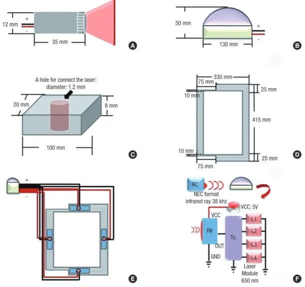
max5.0 mW, working current is min10 mA–max25 mA, working volt- age is min2.3 VDC–max8.0 VDC, wavelength is 650 nm, color is red, diameter is 12 mm, and length is 35 mm. The timer chip is an ATmega88 AVR Microcontroller (Atmel Corporation, San Jose, CA, USA), power is 1.8–5.5 V, and the infrared ray receiv- ing device is an LTOP-ML38ATH (Lite-on, Taipei, Taiwan), which is a one-mold small-package type that uses a 5 V supply. The
ATmega88 AVR Microcontroller and the infrared ray receiving device were fixed on a self-made dome-shaped plastic object with a diameter of 130 mm and a height of 50 mm. The support- ing frame used to fix the laser diode module is made of polysty- rene and it is 100 mm wide, 8 mm tall, and 20 mm deep. A 12 mm diameter hole was prepared in the center so that the laser diode module can be placed inside. The acryl panel is 415 × 330 mm. An area 75 mm wide and 15 mm long on both sides of the acryl panel were cut off so that the panel would not interfere with the detector-fixing device. If the acryl panel were to cover the detector, it would absorb and scatter X-rays and negatively impact image quality. The internal dimensions are 280 × 365 mm. The red line laser diode module was connected to the tim- er chip and it was confirmed to be operating normally. The la- ser diode module was inserted into the central groove of the sup-
Fig. 1. A schematic diagram of RLBC. (A) Red line laser diode module. (B) The domed plastic container housing the timer chip and infrared ray receiving device, the timer chip, and 4 laser diode modules are connected. (C) Polystyrene laser diode module fixing device. (D) The acryl panel to be combined with the detector. (E) The arrangement of the parts viewed from the bottom. (F) A mimetic diagram of RLBC operation. An NEC format infrared ray with 38 kHz is operated by a remote control. The infrared rays are received by the RIR, the infrared ray receiving device, and 5 V power source. Then, the 4 diode modules at the Tc run for 10 seconds.
RLBC = reversed laser beam collimator, NEC = National Electrical Code, RIR = received infrared ray, Tc = timer chip.
A B
C
E
D
F 12 mm
A hole for connect the laser:
diameter: 1.2 mm
20 mm 8 mm
100 mm
10 mm
75 mm330 mm 130 mm 50 mm
25 mm
415 mm
25 mm 75 mm
RC
RIr Tc
L1 L2 L3 L4 OUT
GND
Laser Module 650 nm VCC
VCC: 5V NEC format
infrared ray 38 khz 10 mm
35 mm +
- +
-
+ -
porting frame. The supporting frame and the acryl panel were fixed with silicon. This was done 4 times so that the laser diode module was fixed in all 4 directions of the acryl panel through the supporting frame. After the acryl panel was fixed to the de- tector, the lasers in the 4 planes were focused on the center of the X-ray generation equipment. The dome containing the tim- er chip and the infrared ray receiving device was fixed to the top of the detector (Fig. 1). The National Electrical Code (NEC) for- mat infrared ray with 38 kHz is operated by remote control. When the infrared ray is detected by the infrared ray receiving device, the power turns on. Then, the 4 diode modules run for 10 sec- onds (Fig. 1).
Test method
The equipment used in this study was a C-arm type Allura Xper FD 20 (Philips, Amsterdam, The Netherlands). In the first test, the iron balls were located on the table within 2 mm of the 4 edges of the image field. The table was located as far out and down as possible, and its height was fixed at 75 cm. Then, 30 ra- diologists were divided into 2 groups. One group worked on the test without the use of the RLBC, and the other group worked on the test after the RBLC was put into place. They performed location fixing until the iron balls entered into the image field (Fig. 2). The time from immediately before the start of table mov- ing until the final imaging (the time for location fixing), the time
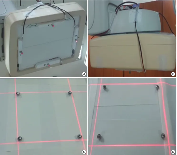
Fig. 2. The RLBC mounted on the instrument. (A) The detector with RLBC as seen from the bottom. (B) Seen from the side. (C) The field confirmed by RLBC after locating the iron balls within 2 mm. (D) The field confirmed by RLBC after locating the iron balls within 10 mm.
RLBC = reversed laser beam collimator.
A
C
B
D
needed for fluoroscopy, and the final dose (DAP) were com- pared between the 2 groups. In the second test, the iron balls were located within 10 mm of the 4 edges of the image field, while all other conditions were the same as in the first test (Fig.
2). Automatic exposure control (AEC) mode was selected when doing fluoroscopy. The tube voltage was 49 kV and the tube cur- rent was 3 mAs. The fluoro-prefilter was 0.40 mmCu + 1.00 mmAl.
SPSS for Windows, version 17.0 (IBM, New York, NY, USA) was used for statistical analyses. Paired t-tests were used to compare the average time needed for location fixing, fluoroscopy, and DAP before and after the use of the RLBC. A P value of 0.001 or smaller was taken to indicate a statistically significant difference.
Measurement of radiation dose during fluoroscopy Measuring the entrance surface dose (ESD) and tissue-absorbed dose with a dose-measuring device is desirable in radiation dose monitoring; however, it is almost impossible to measure those values during actual fluoroscopy. Therefore, the measurement of fluoroscopic time, air kerma at the reference point, and DAP were used to monitor radiation dose. Fluoroscopic time is sig- nificantly related to radiation exposure and it can be easily re- corded without using a separate measuring device; however, the fluoroscopic time is only reference data because it does not reflect the intensity of X-ray irradiation, the performance of the equipment, or the irradiated area. The air kerma at the refer- ence point estimates ESD by calculating or measuring the ener- gy of air particles charged at a fixed reference point. However, the value obtained using the DAP meter, instead of direct mea- surement, contains error because it does not consider scattered rays. DAP is the X-ray intensity within the fluoroscopy area. The DAP meter is located at the front of the collimator of the X-ray tube. In the range limited by collimation, the DAP value is the same regardless of distance and it can be confirmed in real time.
DAP is the most effective measurement method in actual clini- cal practice because it yields the absorbed dose and the effec- tive dose received by a patient through a calculation. Many stud- ies have used DAP to measure the radiation dose. Bor et al. (15) reported that there is not a large difference between the dose directly measured with a thermo-luminescent dosimeter (TLD) and the value obtained by multiplying a conversion factor with the DAP. Therefore, this study used fluoroscopic time and DAP to compare radiation doses.
RESULTS
Existing C-arm type angiography equipment requires the loca- tion of a patient to be determined by fluoroscopy because there is no RLBC; fluoroscopic time and radiation dose are therefore greater than absolutely necessary because of the time needed for location fixing. The test with the iron balls placed within 2 mm of the edges of the image field assumed that the top, bot- tom, left, and right areas of the patient would be focused as much as possible, while the test with the iron balls within 10 mm of the edges of the image field allowed for some margin.
The test with the iron balls within 2 mm of the edges of the image field
In the test with the iron balls within 2 mm of the edges of the image field, the time for location fixing decreased from 23.7 ± 4.7 seconds before using the RLBC to 14.2 ± 3.6 seconds after using the RLBC, the fluoroscopic time decreased from 18.5 ± 4.2 sec- onds before using the RLBC to 2.4 ± 1.9 seconds after using the RLBC, and the DAP decreased from 70.4 ± 10.6 mGycm2 before using the RLBC to 5.5 ± 4.7 mGycm2 after using the RLBC (P <
0.001) (Table 1) (Fig. 3). The average time required for location fixing decreased by 9.5 ± 1.1 seconds, which is a 40.2% decrease.
The fluoroscopic time was reduced by 16.1 ± 2.3 seconds, an 87% decrease, and the DAP changed by 64.9 ± 5.9 seconds, a 92.1% decrease.
The test with the iron balls within 10 mm of the edges of the image field
In the test with the iron balls within 10 mm of the edges of the image field, the time needed for location fixing decreased from 19.0 ± 3.9 seconds before using the RLBC to 5.3 ± 0.5 seconds after using the RLBC, the fluoroscopic time decreased from 13.8
± 3.9 seconds before using the RLBC to 0.8 ± 0.4 seconds after using the RLBC, and the DAP decreased from 58.6 ± 10.1 mGy- cm2 before using the RLBC to 1.4 ± 0.5 mGycm2 after using the RLBC (P < 0.001) (Table 2) (Fig. 4). The difference in the aver- age time needed for location fixing was 13.7 ± 3.4 seconds, which represents a decrease of approximately 71.8%. The difference in fluoroscopic time, 13.0 ± 3.5 seconds, was a 94.2% decrease, and the difference in the DAP, 57.2 ± 9.6 seconds, was a 97.6% de- crease.
Table 1. The test with the iron balls within 2 mm of the edges of the image field
Test Before using the RLBC
(n = 30) After using the RLBC
(n = 30) Difference between before
and after using RLBC Difference between before
and after using RLBC (%) P value
Time for location fixing, sec 23.7 ± 4.7 14.2 ± 3.6 9.5 ± 1.1 −40.2 < 0.001
Fluoroscopic time, sec 18.5 ± 4.2 2.4 ± 1.9 16.1 ± 2.3 −87.0 < 0.001
DAP, mGycm2 70.4 ± 10.6 5.5 ± 4.7 64.9 ± 5.9 −92.1 < 0.001
Calculation of percentage difference between without RLBC and with RLBC is follow as; (Average without RLBC − Average with RLBC)/(Average with RLBC) × 100.
RLBC = reversed laser beam collimator, DAP = dose area product.
DISCUSSION
Radiation exposure from medical procedures brings with it sto- chastic or deterministic risks, such as cancer, cataracts, red spots,
and hair loss. Nevertheless, radiography is widely used in diag- nosis and treatment because the benefits of using radiography outweigh its negatives. Interventional radiography using fluo- roscopy has the merit of enabling diagnosis and treatment at Table 2. The test with the iron balls within 10 mm of the edges of the image field
Test Before using the RLBC
(n = 30) After using the RLBC
(n = 30) Difference between before
and after using RLBC Difference between before
and after using RLBC (%) P value
Time for location fixing, sec 19.0 ± 3.9 5.3 ± 0.5 13.7 ± 3.4 −71.8 < 0.001
Fluoroscopic time, sec 13.8 ± 3.9 0.8 ± 0.4 13.0 ± 3.5 −94.2 < 0.001
DAP, mGycm2 58.6 ± 10.1 1.4 ± 0.5 57.2 ± 9.6 −97.6 < 0.001
Calculation of percentage difference between without RLBC and with RLBC is follow as; (Average without RLBC − Average with RLBC)/Average with RLBC × 100.
RLBC = reversed laser beam collimator, DAP = dose area product.
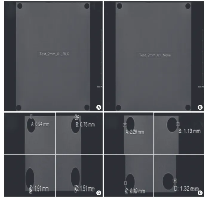
Fig. 3. RLBC in the test with the iron balls within 2 mm from the edges of image field. (A) The image of the fixed location without using the RLBC in the test with the iron balls within 2 mm from the edges of image field. (B) The image of the fixed location when using the RLBC. (C) and (D) Confirmation that the iron balls are within 2 mm from the edg- es of the image field.
RLBC = reversed laser beam collimator.
A B
C D
the same time. It can be used to detect and treat various diseas- es, it is safe, and it results in better or at least the same results as surgery while being less invasive (16,17). However, radiation ex- posure remains an important issue because certain body parts are exposed to radiation for a long period of time and many people in the radiography room, including the patient, inter- ventionist, radiologic nurse, and radiologic technologist, are ex- posed to radiation. This became a concern because of many re- ports on skin damage and hair loss in patients treated with in- terventional radiography (12,14,18). There have also been re- ports on the possibility of disorders developed by intervention- ists because of occupational exposure (19-21). Roguin et al. (22) reported that malignant tumors occurred on the left side of the brains of 4 interventionists, and the tumors were related to the X-ray generation device. In September of 2000, the ICRP rec- ommended, in ICRP publication 85, that dose-decreasing meth- ods should be identified and enforced by evaluating the perfor- mance of radiation equipment and other technical factors. The ICRP also suggested that attention should be paid to the hands of interventionists, which are exposed to direct X-rays, scattered rays, and leaked rays (13). Common methods of decreasing ra- diation exposure in interventional radiography are pulsed fluo-
roscopy (23), radiation protectors (such as wrap-around pro- tective aprons, protective glasses, and ceiling-type protective viewing windows), increasing the distance between the patient and the X-ray tube, decreasing the distance between the image receptor (detector) and the patient, and using high KV and low mAs (24). However, these methods are already considered dur- ing a procedure and they are reflected in the total dose. Even so, the amount of exposure during various procedures has not been resolved. Therefore, new methods of decreasing radiation ex- posure should be considered. Accordingly, this study, inspired by the light collimator used in general radiography, developed a novel method of reducing radiation exposure.
General fluoroscopy equipment used in interventional angi- ography is C-shaped; the X-ray generation device is located un- der a table, on which a patient lies, in order to reduce exposure of the patient/interventionist to radiation, and the imaging de- tector is located above the patient. Therefore, it is not possible to use a light collimator to confirm the X-ray field by locating a small electric bulb on the X-ray generation device, as is done in a general X-ray procedure. This is why location fixing by fluo- roscopy is required to confirm the position of the area of the patient to be irradiated. This study developed an RLBC to elimi-
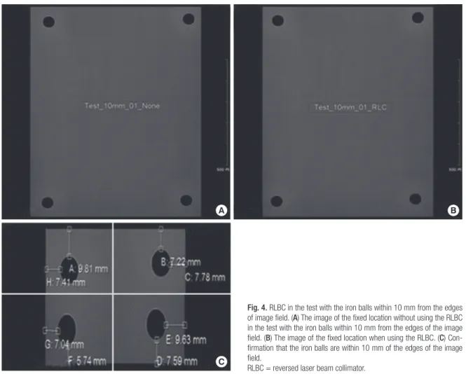
Fig. 4. RLBC in the test with the iron balls within 10 mm from the edges of image field. (A) The image of the fixed location without using the RLBC in the test with the iron balls within 10 mm from the edges of the image field. (B) The image of the fixed location when using the RLBC. (C) Con- firmation that the iron balls are within 10 mm of the edges of the image field.
RLBC = reversed laser beam collimator.
A B
C
nate unnecessary radiation exposure and performed 2 different kinds of tests. In the first case, it was necessary to fix the loca- tion accurately within 2 mm from the edge of the image field. In the second case, a wider margin, 10 mm, was permitted. The tests showed that it was possible to decrease the time needed for location fixing, fluoroscopy time, and the DAP. The time for location fixing decreased by 40.2% and 71.8%, the fluoroscopic time decreased by 87.0% and 94.2%, and the DAP decreased by 92.1% and 97.6% (2 and 10 mm margins, respectively). In other words, using an RLBC allows for much faster identification of the target region than does fluoroscopy, and we confirmed that using RLBC is an effective way to decrease radiation exposure.
Since this study required some images for tests, fluoroscopy was also used in the test with the RLBC; however, it is believed that there would be no radiation received from fluoroscopy in actual clinical location fixing. Therefore, use of an RLBC is a good way to decrease radiation exposure during interventional radi- ography. However, there are some issues with the RLBC at this stage. One issue is that the method may cause infection in pa- tients if the RLBC were to become disengaged because the RLBC is not made by the manufacturer of the X-ray equipment and it is located externally to the detector. Another issue is that mov- ing the detector can cause sensor error. These issues can be re- solved easily by locating the RLBC in the detector when further developing the equipment. The other important issue is that fo- cusing the RLBC, which is done on the basis of the focus of the X-rays, can go wrong if the detector moves up or down. Addi- tional studies are required so that the angle against the X-ray focus can be adjusted depending on the distance between the red line laser diode module and the detector.
In conclusion, the RLBC developed in this study has been confirmed as a new method of decreasing radiation exposure in patients and interventionists during interventional radiogra- phy. However, the RLBC is still in a basic stage and it has certain limitations, which need to be addressed in additional studies.
This study can be utilized for basic information in further devel- oping the RLBC and consequently contributing to decreasing exposure to radiation.
DISCLOSURE
The authors have no potential conflicts of interest to disclose.
AUTHOR CONTRIBUTION
Conceptualization: Heo YC, Cho JH, Han DK. Data curation: Heo YC, Cho JH. Formal analysis: Heo YC, Cho JH. Investigation:
Heo YC, Cho JH, Han DK. Validation: Heo YC, Cho JH, Han DK.
Writing - original draft: Heo YC, Cho JH, Han DK. Writing - re- view & editing: Heo YC, Cho JH, Han DK.
ORCID
Yeong-Cheol Heo https://orcid.org/0000-0003-2938-8531 Jae-Hwan Cho https://orcid.org/0000-0001-7112-3866 Dong-Kyoon Han https://orcid.org/0000-0001-9199-3607 REFERENCES
1. Venkatesan AM, Kundu S, Sacks D, Wallace MJ, Wojak JC, Rose SC, Clark TW, d’Othee BJ, Itkin M, Jones RS, et al. Practice guidelines for adult anti- biotic prophylaxis during vascular and interventional radiology proce- dures. J Vasc Interv Radiol 2010; 21: 1611-30.
2. Söder HK, Manninen HI, Jaakkola P, Matsi PJ, Räsänen HT, Kaukanen E, Loponen P, Soimakallio S. Prospective trial of infrapopliteal artery balloon angioplasty for critical limb ischemia: angiographic and clinical results. J Vasc Interv Radiol 2000; 11: 1021-31.
3. Higashida RT, Tsai FY, Halbach VV, Dowd CF, Smith T, Fraser K, Hieshima GB. Transluminal angioplasty for atherosclerotic disease of the vertebral and basilar arteries. J Neurosurg 1993; 78: 192-8.
4. Wholey MH, Wholey M, Bergeron P, Diethrich EB, Henry M, Laborde JC, Mathias K, Myla S, Roubin GS, Shawl F, et al. Current global status of ca- rotid artery stent placement. Cathet Cardiovasc Diagn 1998; 44: 1-6.
5. Rastan A, Krankenberg H, Baumgartner I, Blessing E, Müller-Hülsbeck S, Pilger E, Scheinert D, Lammer J, Beschorner U, Noory E, et al. Stent place- ment vs. balloon angioplasty for popliteal artery treatment: two-year re- sults of a prospective, multicenter, randomized trial. J Endovasc Ther 2015;
22: 22-7.
6. Byrne JV, Sohn MJ, Molyneux AJ, Chir B. Five-year experience in using coil embolization for ruptured intracranial aneurysms: outcomes and in- cidence of late rebleeding. J Neurosurg 1999; 90: 656-63.
7. Massi F, Muretti M, Coradduzza E, Poddighe C, Terrosu P, Portoghese M.
Myocardial infarction and rupture after bronchial artery embolization.
Ann Thorac Surg 2015; 99: 1051-3.
8. Sakaguchi I, Ohba T, Ikeda O, Yamashita Y, Katabuchi H. Embolization for post-partum rupture of ovarian artery aneurysm: case report and re- view. J Obstet Gynaecol Res 2015; 41: 623-7.
9. Yaacob Y, Nguyen DV, Mohamed Z, Ralib AR, Zakaria R, Muda S. Image- guided chemoport insertion by interventional radiologists: a single-cen- ter experience on periprocedural complications. Indian J Radiol Imag- ing 2013; 23: 121-5.
10. Ahn SJ, Kim HC, Chung JW, An SB, Yin YH, Jae HJ, Park JH. Ultrasound and fluoroscopy-guided placement of central venous ports via internal jugular vein: retrospective analysis of 1254 port implantations at a single center. Korean J Radiol 2012; 13: 314-23.
11. Song WG, Jin GY, Han YM, Yu HC. Central venous catheterization: com- parison between interventional radiological procedure and blind surgi- cal procedure. J Korean Radiol Soc 2002; 47: 467-72.
12. Balter S, Hopewell JW, Miller DL, Wagner LK, Zelefsky MJ. Fluoroscopi- cally guided interventional procedures: a review of radiation effects on patients’ skin and hair. Radiology 2010; 254: 326-41.
13. Valentin J. Avoidance of radiation injuries from medical interventional procedures. Ann ICRP 2000; 30: 7-67.
14. Koenig TR, Mettler FA, Wagner LK. Skin injuries from fluoroscopically guided procedures: part 2, review of 73 cases and recommendations for
minimizing dose delivered to patient. AJR Am J Roentgenol 2001; 177:
13-20.
15. Bor D, Sancak T, Olgar T, Elcim Y, Adanali A, Sanlidilek U, Akyar S. Com- parison of effective doses obtained from dose-area product and air ker- ma measurements in interventional radiology. Br J Radiol 2004; 77: 315- 22.
16. Hwang JS, Hyun MK, Lee HJ, Choi JE, Kim JH, Lee NR, Kwon JW, Lee E.
Endovascular coiling versus neurosurgical clipping in patients with un- ruptured intracranial aneurysm: a systematic review. BMC Neurol 2012;
12: 99.
17. Qureshi AI, Suri MF, Khan J, Kim SH, Fessler RD, Ringer AJ, Guterman LR, Hopkins LN. Endovascular treatment of intracranial aneurysms by using Guglielmi detachable coils in awake patients: safety and feasibility. J Neu- rosurg 2001; 94: 880-5.
18. Koenig TR, Wolff D, Mettler FA, Wagner LK. Skin injuries from fluoroscopi- cally guided procedures: part 1, characteristics of radiation injury. AJR Am J Roentgenol 2001; 177: 3-11.
19. Klein LW, Miller DL, Balter S, Laskey W, Haines D, Norbash A, Mauro MA,
Goldstein JA; Joint Inter-Society Task Force on Occupational Hazards in the Interventional Laboratory. Occupational health hazards in the inter- ventional laboratory: time for a safer environment. Catheter Cardiovasc Interv 2009; 73: 432-8.
20. Sanchez R, Vano E, Fernandez JM, Gallego JJ. Staff radiation doses in a re- al-time display inside the angiography room. Cardiovasc Intervent Radi- ol 2010; 33: 1210-4.
21. Vano E, Ubeda C, Leyton F, Miranda P, Gonzalez L. Staff radiation doses in interventional cardiology: correlation with patient exposure. Pediatr Cardiol 2009; 30: 409-13.
22. Roguin A, Goldstein J, Bar O. Brain tumours among interventional cardi- ologists: a cause for alarm? Report of four new cases from two cities and a review of the literature. EuroIntervention 2012; 7: 1081-6.
23. Hernandez RJ, Goodsitt MM. Reduction of radiation dose in pediatric pa- tients using pulsed fluoroscopy. AJR Am J Roentgenol 1996; 167: 1247-53.
24. Faulkner K. Radiation protection in interventional radiology. Br J Radiol 1997; 70: 325-6.