서 론
진단영역에서 CT의 사용은 해마다 증가되고 있으며 기 계적인 발전도 함께 이루어졌다. 치과영역에서도 점차 CT 의 사용량이 늘고 있으며, 3차원적인 영상으로 재구성하여 악안면부의 선천적 및 후천적 기형의 치료, 두개안면재건 술, 그리고 두개부 내의 장치물의 제작, 임플란트 전 계획, 교정 분석을 위해 사용되기도 한다.1-8
MDCT는 검출기를 여러 층으로 배열한 다중검출기를 이 용하기 때문에 영상 획득 시간이 단축되어 환자의 움직임 등으로 인한 인공음영 (artifact)을 줄일 수 있으며,1,4한번의 촬영으로 3차원적인 영상의 재구성이 가능하다는 장점이 있으나2방사선 노출이 증가된다는 단점이 있다. 2003년의 평가에 따르면 미국 내 방사선과에서 CT를 사용하는 양은
17%지만, 노출량은 75%를 차지한다고 하였다.2방사선 노
출을 합리적으로 달성할 수 있는 한도 내에서 가능한 한 낮게 낮추고 (ALARA; as low as reasonably achievable) 최대 허용선량을 넘지 않게 하는 방사선의 최적화를 위해서1방 사선 노출이 신체에 미치는 영향에 대한 연구와 저노출 촬영법에 대한 연구들이 계속되고 있다.2-6,9-20
접수일 (2010년 1월 15일), 수정일 (2010년 2월 5일), 채택일 (2010년 2월 10일) Correspondence to : Prof. Eun-Kyung Kim
Department of Oral and Maxillofacial Radiology, School of Dentistry, Dankook University, San 7-1, Shinboo-dong, Cheonan, Chungnam, Korea
Tel) 82-41-550-1922, Fax) 82-41-556-7127, E-mail) [email protected]
3차원 안모분석을 위한 저선량 Multi-detector CT 영상의 유효선량 및 화질 평가
단국대학교 치과대학 구강악안면방사선학교실
정기정∙한원정∙김은경
Evaluation of the effective dose and image quality of low-dose multi-detector CT for orthodontic treatment planning
Gi-Chung Chung, Won-Jeong Han, Eun-Kyung Kim
Department of Oral and Maxillofacial Radiology, School of Dentistry, Dankook University ABSTRACT
Purpose : This study was designed to compare the effective doses from low-dose and standard-dose multi-detector CT (MDCT) scanning protocols and evaluate the image quality and the spatial resolution of the low-dose MDCT protocols for clinical use.
Materials and Methods : 6-channel MDCT scanner (Siemens Medical System, Forschheim, Germany), was used for this study. Protocol of the standard-dose MDCT for the orthodontic analysis was 130 kV, 35 mAs, 1.25 mm slice width, 0.8 pitch. Those of the low-dose MDCT for orthodontic analysis and orthodontic surgery were 110 kV, 30 mAs, 1.25 mm slice width, 0.85 pitch and 110 kV, 45 mAs, 2.5 mm slice width, 0.85 pitch. Thermoluminescent dosimeters (TLDs) were placed at 31 sites throughout the levels of adult female ART head and neck phantom. Effective doses were calculated according to ICRP 1990 and 2007 recommendations. A formalin-fixed cadaver and AAPM CT per- formance phantom were scanned for the evaluation of subjective image quality and spatial resolution.
Results : Effective doses in μSv (E2007) were 699.1, 429.4 and 603.1 for standard-dose CT of orthodontic treatment, low-dose CT of orthodontic analysis, and low-dose CT of orthodontic surgery, respectively. The image quality from the low-dose protocol were not worse than those from the standard-dose protocol. The spatial resolutions of both standard-dose and low-dose CT images were acceptable.
Conclusion : From the above results, it can be concluded that the low-dose MDCT protocol is preferable in obtaining CT images for orthodontic analysis and orthodontic surgery. (Korean J Oral Maxillofac Radiol 2010; 40 : 15-23) KEY WORDS : Tomography, Computed; Dosimetry; Orthodontics; Phantoms, Imaging
CT에서 방사선 노출량에 영향을 미치는 요인에는 노이 즈, 관전류, 관전압, 관심영역 (FOV; field of view), pitch, slice width, scanning 방법, 노출 시간 등 여러 가지가 있으 며, 방사선과 의사는 CT의 parameter에 대하여 이해하고 있어야 하며, 부위별로 촬영 목적에 따라 적절한 parameter 를 찾아내야 한다.12,21
국제방사선방어위원회 (ICRP; International Commission on Radiological Protection)는 방사선 검사를 통한 위험도를 비교하기 위한 효과적인 기준으로 유효선량을 정하였다.13 유효선량은 방사선 방어를 위해서 만들어진 것이지만, 신 체의 특정부위 노출로 인한 확률적 효과와 관련된 위험도 를 비교하는 데에도 사용되고 있다. 유효선량은 ICRP 1990 권고안에서 제시한 방법이나 2005년에 수정 제시한 방법 혹은 두 방법 모두를 기초로 계산해 왔다.1,4,15-17,19,20
2007 년에는 ICRP에서 최근의 방사선 노출에 대한 생물학적 및 물리학적 정보를 기초로 한 ICRP 2007 권고안을 새롭게 제시하였다. ICRP 1990과 2007 권고안을 비교해보면 뇌 조 직에 대한 가중치가 증가되었고, 타액선부가 하나의 조직 으로 분류되었으며, 처음으로 구강점막과 외흉부 기도조직 이 조직 가중치의 remainder에 포함되었다.14이와 같은 구 강악안면 부위에 대한 조직 가중치의 변화는 치과방사선 진단에 있어서 위험도가 증가되었음을 의미한다.
단국대학교치과병원에서는 임상에서 MDCT를 이용하여 교정 분석 및 악교정 수술을 위한 촬영 시 노출을 줄이기 위하여 관전류, 관전압, pitch 및 slice width를 조절하여 저 선량 촬영법을 설정하여 사용하고 있다. 본 연구의 목적은 저선량 촬영법으로 촬영했을 때와 제조사에서 제시하는 parameter를 사용하였을 때 (표준선량 촬영)의 유효선량을 측정, 비교하고자 함이며, 아울러 각 촬영에 대한 주관적 화질과 공간 해상도를 비교함으로써 저선량 촬영법이 임 상에서 유효한 화질을 유지하는지 평가하고자 하였다.
재료 및 방법 1. 연구재료
1) 선량 측정
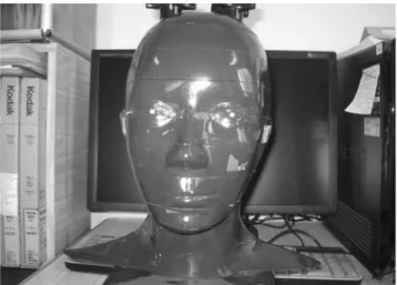
방사선 선량 측정을 위해 인체 골조직과 연조직의 방사 선 감쇠계수와 유사한 ICRU-44 표준에 맞추어 제작된 2.5 cm 두께, 10개 절단면으로 구성된 여자 성인 ART 두경부 모형 (Radiology Support Devices, Inc., Long Beach, USA) (Fig. 1)과 1/8′′×1/8′′×0.035′′의 열발광선량계 TLD-100 Li F chip (Harshaw Chemical Co., USA), Harshaw TLD 4000 reader (Harshaw Chemical Co., USA)를 이용하였다.4
2) 방사선 촬영장치
MDCT 장치로 6채널 MDCT scanner인 Somatom Emotion (Siemens Medical System, Forschheim, Germany), 파노라마
방사선촬영장치로 Planmeca Proloine XC (Planmeca Co., Helsinki, Finland), 측방 두부규격 방사선촬영장치로 Ortho- Phos CD (Siemens Medical System, Foschheim, Germany) 촬 영기를 사용하였다.
3) 화질 평가
주관적 화질을 평가하기 위한 영상은 포르말린으로 고 정한 76세 남자 사체를 이용하여 얻었으며,22공간 해상도 를 평가하기 위해서 AAPM CT performance phantom (Fluke Biomedical Radiation Mangement Services, Fluke Co., USA) (Fig. 2)을 사용하였다.11,23
2. 연구방법
1) 방사선 영상 촬영
두경부 모형에 TLD를 위치시키고 파노라마 방사선촬영 Fig. 1. Female adult ART head and neck phantom was used for the dosimeter location.
Fig. 2. AAPM CT performance phantom with resolution insert which is solid acrylic block (black arrow head) was used for spatial resolution evaluation.
은 68 kV, 6 mA, 18초의 조건으로 촬영하였으며, 측방 두부 규격 방사선촬영은 86 kV, 13 mA, 0.64초의 조건으로 촬영 하였다. 교정 분석 및 악교정 수술을 위한 MDCT의 촬영 은 제조사에서 제시한 조건 (이하 표준선량 촬영)과 단국 대학교치과병원에서 설정하여 환자에게 사용하고 있는 조 건 (이하 저선량)으로 촬영하였다. 교정 분석 및 악교정 수 술을 위한 표준선량 촬영은 130 kV, 35 mAs, 1.25 mm slice width, 0.8 pitch로 촬영하였다. 교정 분석을 위한 저선량 촬 영은 110 kV, 30 mAs, 1.25 mm slice width, 0.85 pitch로, 악 교정 수술을 위한 저선량 촬영은 110 kV, 45 mAs, 2.5 mm slice width, 0.85 pitch로 촬영하였다 (Table 1). 촬영장치마다 동일 조건, 동일 위치에서 기존의 일반 방사선 촬영은 3회 씩 연속 노출하였고,4MDCT는 2회씩 연속 노출하여 측정 하였다.
2) 선량 측정과 유효선량 계산
TLD chip은 방사선에 노출시키기 전에 잔존하는 에너지 를 방출하기 위해 chip container에 넣어 1시간 동안 소성 (annealing)하여 실온에서 식힌 후 다시 100�C에서 2시간 동안 소성하였다. 본 실험에 사용하고자 하는 TLD를 보정 하기 위해서 동일 선량의 방사선에 조사한 후 TLD reader 로 각 TLD chip의 전하량 (nC)을 측정하여 전하량으로부터 mR으로의 변환을 위한 보정 계수를 결정하였다. 이때 조 사된 선량은 Solidose 400 with R100 dose detector (RT1 Elec-
tornics, Inc., Towaco, USA)로 측정하였고, 전 실험과정을 통해 각 chip의 동일성을 유지하였다. 매번 촬영 전에 TLD chip을 소성하여 초기화시킨 후, phantom의 31개 부위에 위치시켜 촬영하였다. 촬영 후 TLD reader로 전하량을 측 정하였고, 측정된 전하량 (nC)은 앞서 결정된 보정 계수를 이용하여 노출선량 (mR)으로 변환시켰다. 변환된 노출선 량 (mR)에 correction factor 8.69를 곱하여 흡수선량 (μGy) 으로 환산하였다.4
TLD는 6개 기관과 조직의 31개 부위에 위치시켰고 부 위는 갑상선 1개, 타액선 4개, 골수 13개, 식도 1개, 피부 7 개, 뇌 1개, 눈 4개를 모형의 각 level에 위치시켰다 (Table 2). 배경 방사선의 양을 측정하기 위해 매 소성 후 동일 조 건에서 따로 보관된 5개의 TLD chip으로 배경 방사선 값 을 측정한 후 개개의 측정치에서 빼어 보정하였다.
이와 같이 환산된 흡수선량을 각 부위별로 평균을 내어, 촬영 시 방사선에 조사되는 조직의 비율을 곱하여 등가선 량 (Equivalent dose (HT); μSv 단위로 표시)을 계산하였고, 유효선량 (Effective dose (E); μSv 단위로 표시)은 각 조직과 장기의 등가선량 (HT)에 조직가중계수 (tissue weighting fac- tor (WT))를 곱한 값의 총합으로 계산하였다.
E==»WT×HT
WT: 조직가중계수 (조직 또는 기관의 전체적인 위험도에
대한 상대적 기여도) HT: 등가선량
2007년의 새로운 ICRP 권고안은 ICRP 1990 권고안에서 포함되지 않았던 뇌 (뇌하수체) 부위와 타액선을 하나의 조 직/기관으로 포함하였고, remainder에 림프선, 구강점막, 외 흉부 기도를 추가하였다 (Table 3).10등가선량을 계산할 때 방사선에 조사되는 조직의 백분율은 갑상선 부위는 100%, 식도는 10%, 두경부의 피부는 전 피부의 5%로 간주하였 다. 하악과 두개골, 경추의 골수 부위는 인체 전체 골수의 16.5% (하악 1.3%, 두개골 11.8%, 경추 3.4%)로 계산하였 다. 피질골의 흡수선량은 평균 골수선량 (marrow dose)에 연조직에 대한 비율요소 (노출을 흡수선량으로 전환하기 위한 요소)인 4.64를 곱하여 계산하였다.4
Table 1.Image taking parameters
Parameter P C O_s O_l_a O_l_s
kV 68 84 130 110 110
mAs 6 mA 13 mA 35 30 45
Collimation 1.00 1.00 1.00
Slide width 1.25 1.25 2.50
Pitch 0.80 0.85 0.85
CTDI vol (mGy) 9.59 5.72 8.58
Time (sec) 18.00 0.64 P: Panoramic radiography
C: Cephalometric radiography
O_s: Standard-dose of orthodontic treatment O_l_a: Low-dose of orthodontic analysis O_l_s: Low-dose of orthodontic surgery
Table 2.Phantom levels with anatomic sites
Level Anatomic sites
0 Vertex
2 Lateral calvarium Posterior calvarium Occipital
3 Pituitary gland Orbit Lens of eye
4 Preauricular
5 Parotid gland
6 Submandubular gland 2nd cervical vertebra 2nd premolar 3rd molar Philtrum
7 Mandibular symphysis Chin
8 Posterior neck
9 Thyroid gland 6th cervical vertebra Oesophagus
유효선량은 1990년의 ICRP 권고안과 2007년의 새로운 ICRP 권고안의 조직가중계수 (tissue weighting factor (WT)) (Table 4)를 둘 다 사용하여 산출하였다. 제안된 2007년 WT에 의해서 1990년 WT에 포함되지 않았던 타액선과 re- mainder였던 뇌를 15개 조직/기관에 추가하였고, remainder 는 14개로 그 중 림프선, 근육조직, 외흉부 기도부위와 구 강점막을 포함시켜 계산하였다.4,9,10,13,20
3) 화질 평가
주관적 평가를 하기 위해서 OnDemand 3D-Quick (Cy-
bermed Inc., Seoul, Korea) 프로그램을 이용하여 영상을 3 차원으로 재구성한 후 5단계의 VAS (Visual Analogue Scale) 를 이용하여 평가하였다 (5-point scale; 1==minimal visibility, 5==maximal visibility).24각각의 영상에 대하여 2차원, 3차 원에 대한 전반적인 화질을 평가하였으며, 교정 분석을 위 한 영상에서는 nasion, orbitale, A point, B point, gonion의 화질을, 악교정 수술을 위한 영상에서는 좌우 상악 제1대 구치의 치근첨, 좌우 하악 제1대구치 부위의 하악관, 좌우 하악지의 피질골 부위의 화질을 평가하였다 (Fig. 3).
교정 분석 및 악교정 수술의 영상 평가는 구강악안면방 Table 3.Estimated fraction of organ irradiation and the dosimeters
used to provide an indication of dose to each organ9,20 Organs/Tissue Fraction indicated
ICRP 1990 ICRP 2007
Bone marrow 16.5 16.5
Mandible 1.3 1.3
Calvaria 11.8 11.8
Cervical spine 3.4 3.4
Thyroid 100 100
Oesophagus 10 10
Skin 5 5
Bone surface 16.5 16.5
Mandible 1.3 1.3
Calvaria 11.8 11.8
Cervical spine 3.4 3.4
Salivary glands - 100
Brain - 100
Remainder
Brain 100 100
Lymphatic nodes - 5
Muscle 5 5
Extrathoracic tissue - 100
Oral mucosa - 100
Eyes 100 100
Table 4.Current and previous International Commission on Radio- logical Protection (ICRP) tissue weighting factors (WT) for calcula- tion of effective dose
Organs/Tissue 1990 WT 2007 WT
Gonads 0.20 0.08
Bone marrow (red) 0.12 0.12
Colon 0.12 0.12
Lung 0.12 0.12
Stomach 0.12 0.12
Bladder 0.05 0.04
Breast 0.05 0.12
Liver 0.05 0.04
Oesophagus 0.05 0.04
Thyroid 0.05 0.04
Skin 0.01 0.01
Bone surface 0.01 0.01
Brain remainder 0.01
Kidney remainder remainder
Salivary glands - 0.01
Remainder 0.05* 0.12†
*: adrenals, brain, upper large intestine, small intestine, kidney, muscle, pancreas, spleen, thymus, uterus
†: adrenals, extrathoracic tissue, gall bladder, heart, kidneys, lymphatic nodes, muscle, oral mucosa, pancreas, prostate, small intestine, spleen, thymus and uterus/cervix
Fig. 3.(A) Multi-planar reconstruct- ed image was obtained for orthodon- tic analysis. (B) 3D reconstructed image was obtained for orthodontic surgery.
A B
사선과 의사 2명, 교정과 의사 1명이 1주일 이상의 간격으 로 무작위 blind test로 2회 평가하였다.3,25구강악안면방사 선과 의사는 5M pixel 해상도의 판독용 모니터 (Wide Inc.,
Korea) 상에서 교정과 의사는 진료실용 모니터 LG LCD
Flatron 17′′ (LG Inc., Korea) 상에서 평가하였다.
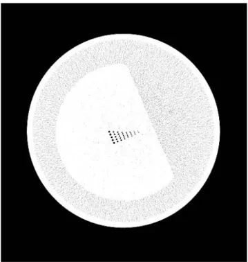
공간 해상도 평가는 CT performance phantom의 공간 해 상도 측정용 블록을 통해 얻은 영상을 window width (300- 400)와 window level (-200--100)을 조절하여 4.3 mm 간 격으로 정렬된 직경 1.75 mm, 1.5 mm, 1.25 mm, 1.00 mm, 0.75 mm, 0.60 mm, 0,50 mm, 0.40 mm의 8단계로 구성된 공 기 구멍 중 최소 식별이 가능한 구멍의 크기를 모니터로부 터 50 cm 이상 떨어져서 확인하였다 (Fig. 4).11,26
4) 분 석
각 촬영 시 얻어진 유효선량을 파노라마 방사선촬영 시 의 유효선량과 비교하였고, 1990년도 ICRP 권고안을 기준 으로 한 경우와 2007 권고안을 기준으로 하여 얻은 유효 선량을 비교하였다. 영상의 화질평가 결과는 paired t-test를 통하여 분석하였으며 SPSS 12.0.1 (SPSS Inc., Chicago, IL, USA)을 사용하였다.
결 과 1. 각 촬영의 유효선량 비교
교정 분석 및 악교정 수술을 위한 표준선량 촬영 시
ICRP 1990 권고안 기준으로 계산한 유효선량은 379.4μSv, ICRP 2007 권고안 기준으로 계산한 유효선량은 699.1μSv 이었다 (Table 5).
교정 분석을 위한 저선량 촬영 시 ICRP 1990 권고안 기 준으로 계산한 유효선량은 229.6μSv, ICRP 2007 권고안 기준으로 계산한 유효선량은 429.4μSv이었다(Table 6).
악교정 수술을 위한 저선량 촬영 시 ICRP 1990 권고안 기준으로 계산한 유효선량은 334.2μSv, ICRP 2007 권고안 기준으로 계산한 유효선량은 603.1μSv이었다(Table 7).
파노라마 방사선촬영 시 ICRP 1990 권고안 기준으로 계 산한 유효선량은 12.1μSv, ICRP 2007 권고안 기준으로 계 산한 유효선량은 27.0μSv이었다(Table 8).
측방 두부규격 방사선촬영 시 ICRP 1990 권고안 기준으 로 계산한 유효선량은 5.3μSv, ICRP 2007 권고안 기준으 로 계산한 유효선량은 7.4μSv이었다(Table 9).
각 촬영 시 ICRP 1990 권고안을 기준으로 얻어진 유효 Fig. 4.CT performance phantom image was obtained for spatial
resolution.
Table 5.Effective dose for orthodontic treatment by standard- dose (μSv)
Tissue/Organ Effective dose
ICRP 1990 WT ICRP 2007 WT
Bone marrow 159.5 159.5
Oesophagus 6.3 5.0
Thyroid 88.4 70.7
Bone surface 61.7 61.7
Brain - 84.9
Salivary glands - 111.6
Skin 5.0 5.0
Remainder
Oral mucosa 56.3 96.3
Lymphatic nodes - 4.8
Muscle 2.3 3.9
Extrathoracic airway - 95.7
Effective dose 379.4 699.1
Table 6.Effective dose for orthodontic analysis by low-dose (μSv) Tissue/Organ Effective dose
ICRP 1990 WT ICRP 2007 WT
Bone marrow 96.7 96.7
Oesophagus 0.1 0.1
Thyroid 56.2 45.0
Bone surface 37.4 37.4
Brain - 51.7
Salivary glands - 69.7
Skin 3.1 3.1
Remainder
Oral mucosa 34.7 60.6
Lymphatic nodes - 3.0
Muscle 1.4 2.4
Extrathoracic airway - 59.8
Effective dose 229.6 429.4
선량을 비교해 보았을 때, 교정 진단 및 악교정 수술을 위 한 표준선량 촬영, 저선량 교정 진단을 위한 저선량 촬영 시, 악교정 수술을 위한 저선량 촬영 시의 유효선량은 파노 라마와 측방 두부규격 방사선촬영 시의 유효선량의 합의 21.8배, 13.2배, 19.2배 정도가 되었다. ICRP 2007 권고안 사 용시 교정 분석 및 악교정 수술을 위한 표준선량 촬영, 교 정 진단을 위한 저선량촬영, 악교정 수술을 위한 저선량촬 영 시의 유효선량은 파노라마와 측방 두부규격 방사선촬영
시의 유효선량의 합의 20.3배, 12.5배, 17.5배가 정도가 되 었다 (Table 10).
각 촬영에 대한 유효선량은 ICRP 1990 권고안에 기준으 로 한 것과 비교하여 새로운 ICRP 2007 권고안을 기준으로 했을 때 40.4%에서 137.7%까지 높게 나타났다 (Table 11).
2. 각 촬영에 대한 영상의 화질 평가
교정 분석 및 악교정 수술을 위한 촬영에서 표준선량 촬 영과 저선량 촬영 시 모두 우수한 화질을 보였으며, 유의
Table 9.Effective dose for cephalometric radiography (μSv) Tissue/Organ Effective dose
ICRP 1990 WT ICRP 2007 WT
Bone marrow 1.5 1.5
Oesophagus 0.2 0.2
Thyroid 2.0 1.6
Bone surface 0.6 0.6
Brain - 0.6
Salivary glands - 1.1
Skin 0.0 0.0
Remainder
Oral mucosa 0.8 0.9
Lymphatic nodes - 0.0
Muscle 0.0 0.0
Extrathoracic airway - 0.9
Effective dose 5.3 7.4
Table 8.Effective dose for panoramic radiography (μSv) Tissue/Organ Effective dose
ICRP 1990 WT ICRP 2007 WT
Bone marrow 1.4 1.4
Oesophagus 0.3 0.3
Thyroid 3.3 2.7
Bone surface 0.6 0.6
Brain - 0.3
Salivary glands - 9.5
Skin 0.0 0.0
Remainder
Oral mucosa 6.4 3.2
Lymphatic nodes - 0.3
Muscle 0.1 0.1
Extrathoracic airway - 8.8
Effective dose 12.1 27.0
Table 10.Effective dose, ratio to panoramic and cephalometric radiography for orthodontic treatment (ICRP 1990 WT and ICRP 2007 WT)
P C O_s O_l_a O_l_s Effective dose; μSv 12.1 5.3 379.4 229.6 334.2 (ICRP 1990 WT)
Ratio 1.0 0.4 21.8 13.2 19.2
Effective dose; μSv
27.0 7.4 699.1 429.4 603.1 (ICRP 2007 WT)
Ratio 1.0 0.3 20.3 12.5 17.5
P: Panoramic radiography C: Cephalometric radiography
O_s: Standard-dose of orthodontic treatment O_l_a: Low-dose of orthodontic analysis O_l_s: Low-dose of orthodontic surgery
Table 11.Effective dose from each examination : comparison of ICRP 1990 and ICRP 2007 calculations
Examination Effective dose, μSv, Effective dose, μSv, Change in effective dose, ICRP 1990 WT ICRP 2007 WT 1990-2007 (%)
Panoramic radiography 12.1 27.0 123.3
Cephalometric radiography 5.3 7.4 40.4
Standard-dose of orthodontic treatment 379.4 699.1 84.3
Low-dose of orthodontic analysis 229.6 429.4 87.0
Low-dose of orthodontic surgery 334.2 603.1 80.5
Table 7.Effective dose for orthodontic surgery treatment by low- dose (μSv)
Tissue/Organ Effective dose
ICRP 1990 WT ICRP 2007 WT
Bone marrow 141.1 141.1
Oesophagus 5.9 4.7
Thyroid 78.4 62.8
Bone surface 54.6 54.6
Brain - 74.6
Salivary glands - 92.2
Skin 4.5 4.5
Remainder
Oral mucosa 47.7 82.3
Lymphatic nodes - 4.0
Muscle 2.0 3.4
Extrathoracic airway - 79.1
Effective dose 334.2 603.1
한 차이가 없었다 (p¤0.05) (Table 12, 13).
각 MDCT 촬영에 대한 공간 해상도 평가에서 교정 분석 및 악교정 수술을 위한 표준선량 촬영과 악교정 수술 계획 을 위한 저선량 촬영에서 0.75 mm의 최소식별이 가능하였 고, 그 외의 모든 촬영에서는 허용기준치인 1.0 mm에서 식 별이 가능하였다 (Table 14).
고 찰
치과영역에서의 CT 촬영은 전체 방사선 검사에 비하여 적은 비율을 차지하지만 방사선 노출은 의료 영역에서와 마찬가지로 매우 높을 것으로 여겨지며, 이를 위한 낮은 선 량의 방법 (저선량 촬영)을 찾기 위한 여러 parameter의 조 절이 필요하다.2
본 연구에서는 6-채널 MDCT를 이용하여 저선량 촬영 법을 설정하여 촬영한 경우의 유효선량을 평가하고자 하였 다. MDCT에서 저선량 촬영의 조건은 임상과정을 통하여 설정하였고, 제조사에서 제시한 방법에 비하여 낮은 CTDI (vol) 값을 확인할 수 있었다.
임상에서 CT의 촬영이 늘어남에 따라 환자가 받는 유효 선량도 간과할 수 없으며, 특히 교정 분석을 위한 촬영은 청소년기의 환자를 대상으로 하기 때문에 방사선 노출의 위험도를 인지하고 이를 줄이는 저선량 촬영에 관한 연구 들이 있었다.27본 연구에서는 표준선량 촬영과 임상적으로 단국대학교 치과병원에서 촬영하고 있는 방법 저선량 촬 영으로 촬영 시 환자가 받는 유효선량을 ICRP 19905와 ICRP 2007 권고안을 기준으로 계산하였다.
ICRP 2007 권고안에서는 이전의 ICRP 1990 권고안보다 구강영역에 대한 조직가중계수가 추가되고 증가되었다. 지 금까지 ICRP 1990과 ICRP 2007 권고안에 기초하여 유효 선량을 비교한 연구들은 많이 발표되고 있다.1,4,15-17,19,20
본 연구도 ICRP 1990과 ICRP 2007 권고안에 기초한 유효선 량을 비교하기 위하여 두 가지 방법을 모두 사용하였다.
교정 분석 및 악교정 수술을 위한 표준선량 촬영과 교정 분석을 위한 저선량, 악교정 수술을 위한 저선량 촬영의 유 효선량은 ICRP 1990 권고안을 기준으로 하였을 때 379.4 μSv, 229.6 μSv, 334.2 μSv이었으며 ICRP 2007 권고안을 기 준으로 하였을 때는 699.1μSv, 429.4 μSv, 603.1 μSv로 파 노라마와 측방 두부규격 방사선촬영 시의 유효선량의 합보 다 21.8배, 13.2배, 19.2배, 20.3배, 12.5배, 17.5배였다. 선학 들의 연구4,9,10,13에 따르면 여러 기종의 CBCT 유효선량은 파노라마 방사선촬영 시의 유효선량에 대하여 2.2배에서 44배라고 보고하였다. Roberts 등10은 기존의 CT 촬영 시의 유효선량이 2,000μSv라고 보고하였으므로 본 연구의 결과 는 이보다 현저히 낮은 것을 알 수 있다. 본 연구의 유효선 량 계산은 Ludlow 등13이 제안한 방법을 사용하였으며, 파 노라마와 측방 두부규격 방사선 촬영 시의 유효선량을 기 준으로 비교하였다. 파노라마 방사선촬영과 측방 두부규격 방사선 촬영은 교정 진단에서 기본이 되는 촬영으로서 일 반 치과의사들이 이해하고 수용하기에도 좋을 것으로 여 겨진다.
전반적으로 ICRP 1990와 비교하여 ICRP 2007 권고안의 유효선량이 40.4%에서 137.7% 더 높게 나타났다. 유효선 량을 구하는 방법은 Ludlow의 방법을 따랐는데, 각 장기의 등가선량을 구할 때 타액선 (이하선, 악하선)의 흡수선량이 많이 이용되었다. 타액선은 물론이고 remainder의 림프조 직, 외흉부 기도, 구강점막도 타액선의 흡수선량을 이용하 여 계산하였고, 외흉부 기도와 구강점막 그리고 타액선은
100%로 간주하여 계산하였다.9타액선의 노출이 구강악안
면영역의 유효선량에 큰 영향을 미치는 요소임을 볼 수 있다.
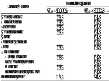
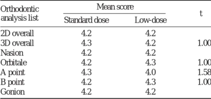
Table 12.Comparison of image quality between standard-dose and low-dose for orthodontic analysis
Orthodontic Mean score
analysis list Standard dose Low-dose t
2D overall 4.2 4.2 -
3D overall 4.3 4.2 -1.00
Nasion 4.2 4.2 -
Orbitale 4.2 4.3 1.00
A point 4.3 4.0 -1.58
B point 4.2 4.3 1.00
Gonion 4.2 4.2 -
*: p⁄0.05
Table 13. Comparison of image quality between standard-dose and low-dose for orthodontic surgery
Orthodontic Mean score
surgery list Standard dose Low-dose t
2D overall 4.2 4.3 1.00
3D overall 4.3 4.3 -
#16 root tip 4.3 4.5 1.00
#26 root tip 4.3 4.5 1.00
#36 mandibular canal 4.0 4.0 -
#46 mandibular canal 4.2 4.2 -
Ramus thickness 4.3 4.3 -
*: p⁄0.05
Table 14.Evaluation of spatial resolution
O_s O_l_a O_l_s
kV 130 110 110
mAs 35 30 45
Mim (mm) 0.75 1 0.75
O_s: Standard-dose of orthodontic treatment O_l_a: Low-dose of orthodontic analysis O_l_s: Low-dose of orthodontic surgery
영상의 질을 평가할 때는 주관적 평가를 사용하였고24 각각의 landmark는 임상에서 주로 고려하는 사항과28해부 학적으로 비교적 독립적인 부위를 선택하여24,25,29평가하고 자 하였다. 평가자는 전반적으로 모두 해부학적 구조물이 잘 보인다고 평가하였다. 선량 연구는 많은 선학들에2-
6,9,10,12-20,30
의하여 보고되어 왔지만 선량과 영상의 질을 모 두 평가한 경우는 드문 것을 고려해 본 연구에서 함께 평 가해 보았다. 하지만 영상의 질을 주관적으로 평가하기 위 해서는 앞으로 더 많은 사체의 촬영으로 술자 간, 술자 내, 관찰기간 간 등의 차이에 대한 평가 연구가 이루어져야 할 것으로 보인다.23
CT의 객관적인 영상의 질을 평가하기 위해서 일반적으 로 공간 해상도와 영상의 대조도 및 노이즈에 대한 평가를 한다.12공간 해상도는 작은 크기의 대조도 차이 (100 HU)가 높은 물질이 인접하여 있을 때의 식별능력을 보는 것으로, 본 연구에서는 CT performance phantom의 공간 해상도 block을 이용하였다. 합격 기준은 1 mm이며, 본 연구에서 는 모두 1 mm 이하의 공기구멍의 구별이 가능하였다.
이상의 결과를 종합해 볼 때 영상의 질의 저하를 일으 키지 않으면서 유효선량을 낮추는 저선량 촬영은 방사선 위험도를 낮춤으로 환자와 술자에게 바람직한 방법이라고 결론지을 수 있었다
참 고 문 헌
1. Association of Korean Professors of Oral and Maxillofacial Radiology.
Oral and Maxillofacial Radiology. 4th ed., Seoul; Narae Publishing;
2008. p. 23-4, 181-4, 226-34.
2. Lee CL, Kim HJ, Jeon SS, Nam SR, Cho HM, Jung JY. Dose measure- ments using phantoms for tube voltage, tube current, slice thickness in MDCT. Korean J Med Phys 2007; 18 : 139-43.
3. Mulkens TH, Broers C, Fieuws S, Termote JL, Bellnick P. Comparison of effective doses for low-dose MDCT and radiographic examination of sinuses in children. AJR Am J Roentgenol 2005; 184 : 1611-8.
4. Lee JN, Han WJ, Kim EK. Absorbed and effective dose from newly developed cone beam computed tomography in Korea. Korean J Oral Maxillofac Radiol 2007; 37 : 93-102.
5. Philipp MO, Funovics MA, Mann FA, Herneth AM, Fuchsjaeger MH, Grabenwoeger F, et al. Four-channel multidetector CT in facial frac- tures: Do we need 2×0.5 mm collimation? AJR Am J Roentgenol 2003; 180 : 1707-13.
6. Bonel HM, Jager L, Frei KA, Galiano S, Srivastav SK, Flohr T, et al.
Optimization of MDCT of the wrist to achieve diagnostic image quality with minimum radiation exposure. AJR Am J Roentgenol 2005; 185 : 647-54.
7. Cohnen M, Fischer H, Hamacher J, Lins E, Kotter R, Modder U. CT of the head by use of reduced current and kilovoltage: relationship between image quality and dose reduction. AJNR Am J Neuroradiol 2000; 21 : 1654-60.
8. Hashimoto K, Kawashima S, Araki M, Iwai K, Sawada K, Akiyama Y.
Comparison of image performance between cone-beam computed tomography for dental use and four-row multidetector helical CT. J
Oral Sci 2006; 48 : 27-34.
9. Ludlow JB, Davies-Ludlow LE, Brooks SL, Howerton WB. Dosimetry of 3 CBCT devices for oral maxillofacial radiology: CB Mercuray, NewTom 3G and i-CAT, Dentomaxillofac Radiol 2006; 35 : 219-26.
10. Roberts JA, Drage NA, Davies J, Thomas DW. Effective dose from cone beam CT examinations in dentistry. Br J Radiol 2009; 82 : 24-40.
11. Han CW, Kim GT, Choi YS, Hwang EH. Image characteristics of cone beam computed tomography using a CT performance phantom.
Korean J Oral Maxillofac Radiol 2007; 37 : 157-63.
12. Paterson A, Frush DP. Dose reduction in paediatric MDCT: general principles. Clin Radiol 2007; 62 : 507-17.
13. Ludlow JB, Davies-Ludlow LE, White SC. Patient risk related to common dental radiographic examinations: The impact of 2007 inter- national commission on radiological protection recommendations regarding dose calculation. J Am Dent Assoc 2008; 139 : 1237-43.
14. Wrixon AD. New ICRP recommendations. J Radiol Prot 2008; 28 : 161-8.
15. Silva MAG, Wolf U, Heinicke F, Bumann A, Visser H, Hirsch E.
Cone-beam computed tomography for routine orthodontic treatment planning: a radiation dose evaluation. Am J Orthod Dentofac Orthop 2008; 133 : 640.3e1-640.e5.
16. Hirsch E, Wolf U, Heinicke F, Silva MAG. Dosimetry of the cone beam computed tomography Veraviewepocs 3D compared with the 3D Accuitomo in different fields of view. Dentomaxillofac Radiol 2008;
37 : 268-73.
17. Ludlow JB, Davies-Ludlow LE, Brooks SL. Dosimetry of two extraoral direct digital imaging devices: NewTom cone beam CT and Orthophos Plus DS panoramic unit. Dentomaxillofac Radiol 2003; 32 : 229-34.
18. Chapman VM, Kalra M, Halpern E, Grottkau B, Albright M, Jaramillo D. 16-MDCT of the posttraumatic pediatric elbow: optimum parame- ters and associated radiation dose. AJR Am J Roentgenol 2005; 185 : 516-21.
19. Ludlow JB. Regarding “Influence of CBCT exposure conditions on radiation dose”. J Am Dent Assoc 2008; 106 : 627-9.
20. Ludlow JB, Ivanovic M. Comparative dosimetry of dental CBCT devices and 64-slice CT for oral and maxillofacial radiology. Oral Surg Oral Med Oral Pathol Oral Radiol Endod 2008; 106 : 106-14.
21. Cody DD, Moxley DM, Krugh KT, O’Daniel JC, Wagner LK, Eftekhari F. Strategies for formulation appropriate MDCT techniques when imaging the chest, abdomen, and pelvis in pediatric patients. AJR Am J Roentgenol 2004; 182 : 849-59.
22. Hashimoto K, Kawashima S, Kameoka S, Akiyama Y, Honjoya T, Ejima K, et al. Comparison of image validity between cone beam com- puted tomography for dental use and multidetector row helical com- puted tomography. Dentomaxillofac Radiol 2007; 36 : 465-71.
23. Tack D, Widelec J, Maertelaer VD, Bailly JM, Delcour C, Gevenois PA. Comparison between low-dose and standard-dose multidetector CT in patients with suspected chronic sinusitis. AJR Am J Roentgenol 2003; 181 : 939-44.
24. Gijbels F, Sanerink G, Van Dam J, Nowak B, Jacobs R. Radiation doses of indirect and direct digital cephalometric radiography. Br Dent J 2004; 197 : 149-52.
25. Arrive L, Renard R, Carrat F, Belkacem A, Dahan H, Hir PL, et al. A scale of methodological quality for clinical studies of radiologic exami- nation. Radiology 2000; 217 : 69-74.
26. Jang KJ, Kweon DC. Case study of quality assurance for MDCT image quality evaluation using AAPM CT performance phantom. Korea Contents 2007; 7 : 114-23.
27. Lee YJ. Optimization of Somatom Emotion 6 Multi detector CT for
3D image in orthodontic diagnosis with minimal radiation exposure
‘Unpublished doctoral dissertation’. Yeongin, Dankook Univ, 2008.
28. Choi JS, Kim EK, Han WJ. The accuracy of reformatted images using a new virtual 3-dimensional dental implant system. Korean J Oral Maxillofac Radiol 2003; 33 : 187-93.
29. Trpkova B, Major P, Prasad N, Nebbe B. Cephalometric landmarks
identification and reproducibility: A meta analysis. Am J Orthod Den- tofac Orthop 1997; 112 : 165-70.
30. Cho JY, Han WJ, Kim EK. Absorbed and effective dose from periapi- cal radiography by portable intraoral x-ray machine. Korean J Oral Maxillofac Radiol 2007; 37 : 149-56.