MH 수소저장 장치의 방출시 열거동 모사 수치 모델 개발
오상근*, 조성욱**, 이경우* †
*서울대학교 재료공학부, **한국 지질자원 연구원
Development of a Thermal Model for Discharge Behavior of MH Hydrogen Storage Vessels
SANGKUN O*, SUNGWOOK CHO**, KYUNGWOO YI* †
*Department of Materials Science and Engineering, Seoul National University, 1 Gwanak-ro, Gwanak-gu, Seoul, Korea
**Korea Institute of Geoscience and Mineral Resouces, 92 Gwahang-no, Yuseong-gu, Daejeon, Korea
ABSTRACT
Metal hydride alloys are a promising type of material in hydrogen storage applications, allowing for low-pressure, high-density storage. However, while many studies are being performed on enhancing the hydrogen storage properties of such alloys, there has been little research on large-scale storage vessels which make use of the alloys. In particular, large-scale, high-density storage devices must make allowances for the inevitable generation or absorption of heat during use, which may negatively impact functioning properties of the alloys. In this study, we develop a numerical model of the discharge properties of a high-density MH hydrogen storage device. Discharge behavior for a pilot system is observed in terms of temperature and hydrogen flow rates. These results are then used to build a numerical model and verify its calculated predictions. The proposed model may be applied to scaled-up applications of the device, as well as for analyses to enhance future device designs.
KEY WORDS : Numerical analysis(전산 모사), Metal hydrides(수소화 합금), Hydrogen storage(수소 저장), Thermal model(열 해석 모델)
† Corresponding author : [email protected]
[
접수일: 2011.4.1
수정일: 2011.4.15
게재확정일: 2011.4.22 ]
1. Introduction
Hydrogen storage is a major issue which must be resolved for development of a viable, efficient
hydrogen economy 1) . Many storage technologies including high pressure gas or liquid-state storage are hindered by issues such as low volumetric storage density, systemic instability and cost.
Certain metal alloys have been shown to be a
promising alternative, with many numerous
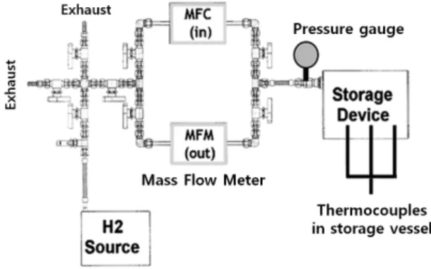
Fig. 1 Pilot system for bulk-scale data acquisition.
previous studies demonstrating their ability to absorb and release hydrogen in significant quantities.
Moreover, hydrogen storage in metal hydrides offers potential benefits such as high volumetric density and stable, low pressure utilization 1) . One type of alloy with promising hydrogen storage properties is the TiCrV alloy 2,3) and TiCrV-Fe alloy 4) . These alloys have been shown to demonstrate high reversible storage capacities and resiliency through multiple cycles.
However, utilization of these alloys in practical applications has been hindered by the comparatively low volume of research being performed on their bulk behavior or storage device designs for such materials in large-scale applications. Moreover, high costs and low practicality make it difficult to perform experimentation on large-scale devices or systems. This is particularly true in a climate with domestic investment in hydrogen research being more heavily focused on production than on storage or distribution 5) .
In this study, we address this issue by developing a numerical analysis model of the discharge pro- perties of an MH storage system based on measured properties from a pilot system using TiCrV-Fe alloy. The numerical modeling takes into account key parameters such as the inevitable absorption of heat during hydrogen release, which may nega- tively impact the storage properties of the alloy 1,6,7) . The model allows for prediction of the thermal behavior of an MH vessel during hydrogen release, and may be applied to different configurations of MH systems, and in further studies to enhance future device designs.
2. Experimental Method 2.1 Pilot System
In order to obtain bulk-scale data of the TiCrV-
Fe alloy used in the present study, we built a pilot system with a simple hydrogen storage device based on prior simulations intended to optimize both reaction rates and temperature control. The system, as illustrated in Figure 1, makes it possible to obtain temperature readings from various loca- tions within the hydride beds by employing stra- tegically placed thermocouples, as well as gas flow rates for both absorption and desorption through a mass flow controller .
2.2 Numerical Modeling
Because of limitations arising from high cost and practicality, production of large amounts of alloys and direct experimentation on multiple devices utilizing them is prohibitively difficult. As a result, studies regarding the impact of certain variables on device efficiency are often limited to a single design 7) .
A convenient and effective alternative to direct experimentation is to predict the behavior of systems in question using numerical simulation.
Several studies adopting this method have been
reported in the literature 8-11) . Unfortunately, most
of these studies are not performed in tandem with
direct analysis of real alloy samples. In this study,
bulk material properties are first obtained from a
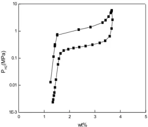
0 1 2 3 4 5 1E-3
0.01 0.1 1 10