전기기관차(8200호대) 신규 보조전원장치 적용 시 MVB 통신프로토콜 중 고장코드에 관한 연구
배영규
*
ㆍ신화송*
ㆍ정휘섭**
ㆍ손기환***
A Study on the Failure code of the MVB Protocol when the Electric locomotive(8200 series) New Auxiliary Power Supply is applied
Young-Kyu Bae
*ㆍHwa-Song Shin
*ㆍHwi-Seob Jeong
**ㆍKi-Hwan Son
***요 약
현재 운용되고 있는 전기기관차(8200호대) 전장품의 부분적 국산화를 위해서는 전기기관차내의 장치간 MVB 통신프로토콜에 대한 분석이 우선 진행되어야 한다. 그 중에서도 신규 개발된 보조전원장치가 적용되었을 때 우 려되는 사항인 고장발생 시 동작에 대한 분석이 필요하다. 본 논문에서는 분석된 통신프로토콜을 적용한 신규 개발 통신제어장치를 통해 신규 보조전원장치를 기존 전기기관차에 적용하였을 때 정상동작 뿐만 아니라 고장발 생 시 동작에도 문제없이 작동하도록 고장코드에 대한 MVB 통신프로토콜을 분석하였다.
ABSTRACT
In order to partially localize the electric locomotive(8200 series) currently being operated, analysis of the inter-device MVB protocol in the electric locomotive should be performed first. Especially, it is necessary to analyze the operation when a newly developed auxiliary power supply is applied. In this paper, when a new auxiliary power supply applied to a conventional electric locomotive through a newly developed communication control unit using the analyzed protocol, a protocol for a failure codes was analyzed.
키워드
Electric Locomotive, 8200 Series, Auxiliary Power Supply, Communication Control Unit, MVB Protocol, Failure Code 전기 기관차, 8200호대, 보조 전원 장치, 통신 제어 장치, MVB 프로토콜, 고장 코드
* ㈜앤츠 부설연구소 ([email protected], [email protected])
** 한국철도공사 철도과학기술연구원 ([email protected])
*** 교신저자 : ㈜앤츠 부설연구소 연구소장
ㆍReceived : Jan. 30, 2018, Revised : Mar. 08, 2018, Accepted : Apr. 15, 2018 ㆍCorresponding Author : Ki-Hwan Son
R&D Center, Ants Co., Ltd Email : [email protected]
Ⅰ. 서 론
현재 전기기관차(8200호대)는 총 83량이 운용되고 있으며 사용 연수가 평균 10년을 초과한 상태로 고장 발생 시 부품 수급 및 유지보수에 어려움을 겪고 있 어 호환이 가능한 전장품을 개발 적용하는 부분적 국
산화를 추진하고 있다[1]. 국산화 개발을 진행함에 있
어서 기존품보다 성능 및 유지보수성이 뛰어난 개발
품이 적용되어야 함은 물론이고 기존품과 개발품과의
원활한 인터페이스를 위해 전기기관차 내의 장치 간
통신프로토콜 분석이 우선시 되어야 한다. 기존 보조
전원장치를 신규 개발된 보조전원장치[2]로 대체하여
http://dx.doi.org/10.13067/JKIECS.2018.13.2.377
적용하였을 때 가장 우려되는 사항은 고장발생 시 중 앙제어장치(CCU, Central Control Unit)에서의 통제가 제대로 되지 않는 상황이 발생하는 것으로 동작 중지 및 연장급전이 기존과 동일하게 되어야 연결되어 있 는 다른 장치들의 추가 고장을 막을 수 있고 열차의 운행에 지장이 없을 것이다. 따라서 고장발생 시 중앙 제어장치로 제대로 된 고장정보를 전달하는 것이 중 요하다. 본 논문에서는 신규 개발된 통신제어장치를 통해 기존 중앙제어장치와 신규 보조전원장치를 인터 페이스하여 고장코드에 대한 MVB(: Multifunction Vehicle Bus) 통신프로토콜을 분석하였다.
Ⅱ. 본 론
2.1 프로토콜 분석기(Analyzer)
MVB 통신프로토콜 분석을 위해 자체 개발 제작된 MVB Analyzer의 기능인 MVB 통신 데이터 로그 채 취, 외부신호 채취 및 생성, MVB 통신 프로토콜 생 성을 통해서 프로토콜 채취 및 분석을 진행하였다 [3-4].
2.2 프로토콜 분석
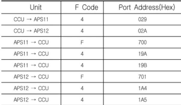
분석기를 통해 분석한 중앙제어장치와 보조전원장 치 간 F code와 Port address를 표 1에 나타내었다.
Unit F Code Port Address(Hex)
CCU → APS11 4 029
CCU → APS12 4 02A
APS11 → CCU F 700
APS11 → CCU 4 19A
APS11 → CCU 4 19B
APS12 → CCU F 701
APS12 → CCU 4 1A4
APS12 → CCU 4 1A5
표 1. 중앙제어장치와 보조전원장치간 F code와 Port address
Table 1. F Code & Port address between CCU and APS(Auxiliary Power Supply)
중앙제어장치에서 보조전원장치로 전송하는 Port address는 보조전원장치 당 1개씩 총 2개이고, 보조전 원장치에서 중앙제어장치로 전송하는 Port address는 Status port, Process data port, Reserve port 보조전 원장치 당 3개씩 총 6개가 할당되어 있다.
2.2.1 Status port
Status를 전송하는 Port address로 장치의 현재 상 태에 대해서 응답한다.
2byte로 구성되어 있으며 1byte는 장치의 class에 따라 special device, bus administrator, gateway, message data 를 나타내거나 reserved 된다. 나머지 1byte의 1bit마다 Line A 수신, 여분 line 교란, 통신 시스템 장애, 장치 장애, Reply 장애, 강제 장치, 장치 준비, 예비 시스템을 나타낸다[5-6].
2.2.2 Process data port
Process data를 전달하는 Port address이다. 총 32byte로 구성되어 있으며 byte 또는 bit단위로 data 를 전송한다.
중앙제어장치에서 보조전원장치로 전송하는 데이터 는 주회로 차단기 on/off 신호, 출력주파수 지령치, 출 력주파수 변화율 등 운전 지령에 관련된 정보이고 보 조전원장치에서 중앙제어장치로 전송하는 데이터는 입력전류, 입력전압, DClink 전압, 출력전압, 출력주파 수, 각종 고장, 온도 등 보조전원장치의 운전 상황에 관련된 정보를 전송한다.
2.3 프로토콜 신뢰성 검증
프로토콜 생성기를 사용하여 보조전원장치의 컨버
터/인버터 동작 on/off상태를 변화시키는 프로토콜을
CCU 화면표시기로 전송하면 그림 1의 ➀에서 컨버터
/인버터의 동작 상태 on/off를 확인할 수 있고 입력전
압, 입력전류, 주파수, 출력전압 등 파라미터의 값을
변화시키는 프로토콜을 CCU 화면표시기로 전송하면
그림 1의 ➁에서 입력전압, 입력전류, 주파수, 출력전
압 등 파라미터의 값을 확인할 수 있었다. 이를 통해
분석된 프로토콜을 검증할 수 있었다.
그림 1. CCU 화면표시기 화면 현시 Fig. 1 CCU MMI(Man Machine Interface) screen
display
2.4 프로토콜 적용
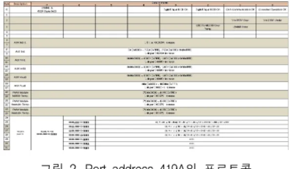
그림 2는 APS11의 데이터를 전송하는 Port address 419A의 프로토콜이고 APS12의 데이터를 전 송하는 Port address 41A4의 프로토콜은 Port address 419A와 대칭된 형태를 가진다.
그림 2. Port address 419A의 프로토콜 Fig. 2 Protocol of Port address 419A
2.4.1 통신제어장치 개발품
기존 통신제어장치인 SIBCOS-M1300을 분석하여 ADC, DAC, Digital Input, Digtal Output, LED, CAN 통신, MVB 통신 등 동일한 기능을 구현할 수 있도록 MCU(Micro Controller Unit)[7-8]를 사용하여 설계 제작하였고[9], 유지보수를 위한 RS232통신과 기본 정보 및 고장 정보을 표시할 수 있는 20x4 Character LCD, 온도 감지를 할 수 있도록 센서를 적용하였다 [10]. 신규 보조전원장치와는 RS485 serial 통신으로
그림 3. 통신제어장치 개발품 블록도
Fig. 3 A block diagram of new developed communication control unit
2.4.2 조합시험
기존 보조전원장치를 탈거하고 개발품 보조전원장 치를 적용하여 정상동작을 확인[11]한 후 고장코드에 대한 프로토콜 분석을 진행하였다.
그림 4. 전체 시스템 배치 Fig. 4 Total system configuration 전체 시스템 배치는 그림 4와 같다.
신규 보조전원장치와 신규 통신제어장치는 RS485 serial 통신으로 인터페이스 되어 있으며 신규 보조전 원장치는 현재의 상태 정보를 전송하고 신규 통신제 어장치는 중앙제어장치로부터 수신한 기동 명령, 출력 지령치 등을 보조전원장치로 전송한다.
신규 통신제어장치와 기존 중앙제어장치는 MVB
Code
ID Failure description
230
APS11: over-temperature SIBCOS
231APS11: over-temperature 4QS
232APS11: over-temperature PWM
233
APS11: SIBCOS switched off with NFB 31-F01
234
APS11: no availability after switch-on
235APS11: status signal of main relay not clear
236APS11: status signal of precharging relay
not clear
237
APS11: no dc-link circuit voltage
238APS11: short circuit at 4QS
239APS11: 4QS locked
240
APS11: break down of AUX without detailed fault annunciation
241
APS11: thermal overload PWM
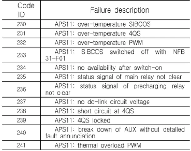
표 2. 보조전원장치 고장코드 Table 2. Auxiliary Power Supply Failure Code
242
APS11: continues overload PWM
243APS11: maximum overload PWM
244
APS11: UCE monitoring responded at PWM
245APS11: short circuit PWM
246
APS11: malfunction AUX-circuit, no regrouping
247
APS11: PWM locked
248
APS11: input voltage detection malfunction
249APS11: latest failure at SIBCOS due to
power supply malfunction
250
APS11: latest failure at SIBCOS due to MVB-malfunction
251
APS11: SIBCOS malfunction
252
APS11: SIBCOS system blower malfunction
260APS12: over-temperature SIBCOS
261APS12: over-temperature 4QS
262APS12: over-temperature PWM
263
APS12: SIBCOS switched off with NFB 31-F01
264
APS12: no availability after switch-on
265APS12: status signal of main relay not clear
266APS12: status signal of precharging relay
not clear
267
APS12: no dc-link circuit voltage
268APS12: short circuit at 4QS
269APS12: 4QS locked
270
APS12: break down of AUX without detailed fault annunciation
271
APS12: thermal overload PWM
272APS12: continues overload PWM
273APS12: maximum overload PWM
274
APS12: UCE monitoring responded at PWM
275APS12: short circuit PWM
276
APS12: malfunction AUX-circuit, no regrouping
277
APS12: PWM locked
278
APS12: input voltage detection malfunction
279APS12: latest failure at SIBCOS due to
power supply malfunction
270
APS12: latest failure at SIBCOS due to MVB-malfunction
281
APS12: SIBCOS malfunction
282
APS12: SIBCOS system blower malfunction
전원장치의 상태정보를 수신한다.
신규 보조전원장치, 신규 통신제어장치, 기존 중앙 제어장치 간 통신 연결도는 그림 5에 나타내었다.
그림 5. 신규 보조전원장치, 신규 통신제어장치, 기존 중앙제어장치 간 통신 연결도
Fig. 5 A communication connection diagram between new APS and new Communication control unit and
CCU
2.5 고장코드
전체 CCU Event Code 690개 중 보조전원장치 관 련 고장코드는 총 46개로 APS11에 해당하는 Code ID는 230부터 252(253부터 259는 사용하지 않음)까지 23개, APS12에 해당하는 Code ID는 260부터 282(283 부터 289는 사용하지 않음)까지 23개이며 표 2에 나 타내었다.
2.5.1 고장코드 검색
신규 보조전원장치를 적용한 상태에서 보조전원장 치의 정보를 중앙제어장치로 전송하는 Port address 인 419A와 41A4를 통해 임의로 고장이 발생한 것처 럼 bit를 변화시켜 고장코드를 검색하였다.
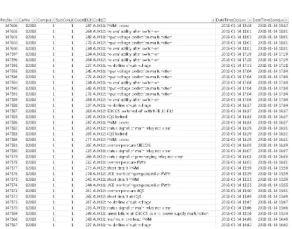
그림 6의 CCU event 확인 프로그램을 통해서 발
생된 고장과 고장코드, 발생시간, 소거시간을 확인하
였다.
그림 6. CCU event 확인 프로그램 고장이력 Fig. 6 CCU event check program history
2.5.2 고장코드 적용
검색된 고장코드가 추가된 프로토콜은 그림 7과 같 으며 총 32byte 중 상태에 관련된 0~5byte를 통해 고 장이 발생했음을 중앙제어장치로 전달한다.
신규 보조전원장치에 고장이 발생하였을 때 중앙제 어장치로 고장 정보를 제대로 전달할 수 있도록 프로 토콜에 적용하였다.
그림 7. 고장코드 추가된 Port address 419A의 프로토콜
Fig. 7 Protocol of Port address 419A with failure code added
Ⅲ. 결론 및 향후개선 방향
보조전원장치를 인터페이스 하였고, 임의로 고장을 발 생시키고 그때의 고장코드를 검색하여 고장코드에 대 한 통신프로토콜을 분석하였다. 향후 고장 발생 시 연 장급전 등 운전 시퀀스에 대한 연구를 진행하여 고장 코드 적용함에 있어서 개선을 할 수 있을 것으로 판 단된다.
감사의 글
이 논문은 국토교통과학기술진흥원의 철도기술사 업으로 지원된 「전기기관차(8200호대) 보조전원 장치 실용화 기술개발」 과제의 연구비 지원에 의한 논문임
References
[1] Korea Railroad Corporation, “Performance improvement technology of propulsion system of electric locomotive(8200 series), Annual report of railway technology research project,” Annual report, Ministry of Land/Korea Agency for Infrastructure Technology Advancement, Dec.
2013.
[2] E. Lee, B. Ahn, J. Jung, and C. Yoon, “A New Development of Auxiliary Power System for 8200 Series Electric Locomotives,” In Proc. Conf. The Korea Society for Railway, Jeju, Korea, Oct. 2014, pp. 591-596.
[3] G. Bae and K. Son, “The Implementation of MVB Communication Protocol Analyzer for Electric Locomotive(Series 8200),” In Proc. Conf.
The Korea Institute of Electronic Communication Sciences, Cheonan, Korea, 2014, pp. 320-323.
[4] G. Bae, K. Son, J. Park, and J. Jun, “A Study on MVB Protocol Analyzer for 8200 Series Electric Locomotives,” In Proc. Conf. The Korea Society for Railway, Busan, Korea, May 2017, pp.
397-401.
Technology Conf., Tokyo, Japan, May 2000, vol.
51, no. 2, pp. 1581-1585.
[6] J. Sul, S. Kim, and J. Park, “Implementation and simulation a slave module based on MVB of the TCN(IEC-61375-1),” In Proc. Conf. The Korea Information Processing Society, Seoul, Korea, 2009, pp. 573-574.
[7] J. Choi and Y. Chung, “Development of Sound Frequency Analyser using an Ultra-Low Power MCU,” J. of the Korea Institute of Electronic Communication Sciences, vol. 11, no. 4, 2016, pp.
403-409.
[8] H. Kim, H. Yoo, Y. Lee, H. Jung, and Y. Ko,
“A Study on the SPWM based Power Conversion Technology of the Three-Phase Photovoltaic Inverter Using DSP,” J. of the Korea Institute of Electronic Communication Sciences, vol.
12, no. 6, 2017, pp. 1099-1106.
[9] W. Kim, K. Lee, N. Jung, C. Chang, J. Kim, and K. Koo, “A Study on the LCC Analysis for SIBCOS of Auxiliary Power System for Electric Locomotive 8200 series,” In Proc. Conf. The Korean Institute of Electrical Engineers, Busan, Korea, 2017, pp. 1576-1577.
[10] G. Kim, “Implementation of Real-time Sensor Monitoring Systime on Zigbee Module,” J. of the Korea Institute of Electronic Communication Sciences, vol. 6, no. 2, Feb. 2011, pp. 312-318.
[11] Y. Bae, B. So, G. Kong, and K. Son, “A Study on MVB Protocol in Communication Control Unit(SIBCOS-M1300) for Auxiliary Power System of 8200 Series Electric Locomotive,” In Proc.
Conf. The Korea Society for Railwayf, Hoengseong, Korea, Aug. 2017, pp. 576-577.
저자 소개
배영규(Young-Kyu Bae)
2009년 동의대학교 전기공학과 졸 업(공학사)
2014년 동의대학교 대학원 전기공 학과 수료
2009년∼2011년 한국전기연구원 위촉연구원 2011년∼2015년 그리드온(주) 주임연구원 2016년∼현재 ㈜앤츠 연구원
※ 관심분야 : MVB 통신, 신호처리, 프로토콜
신화송(Hwa-Song Shin)
1999년 부산대학교 정밀기계공학과 졸업(공학사)
1999년∼2009년 ㈜씨엠케이 기획실장 2012년∼2015년 ㈜더파크 기획실장 2015년∼현재 ㈜앤츠 전략기획부장
※ 관심분야 : 영상처리, 신호처리, HUD
정휘섭(Hwi-Seob Jeong)
2005년 영남대학교 기계공학과 졸 업(공학사)
2005년∼2015년 한국철도공사 2016년∼현재 한국철도공사 연구원
※ 관심분야 : 철도차량 제어 및 통신
손기환(Ki-Hwan Son)