Http://Dx.Doi.Org/10.7840/Kics.2014.39A.2.86
Error-Correcting 7/9 Modulation Codes For Holographic Data Storage
Kyoungoh Lee, Byungsun Kim, Jaejin Lee°
Abstract
Holographic data storage (HDS) has a number of advantages, including a high transmission rate through the use of a charge coupled device array for reading two-dimensional (2D) pixel image data, and a high density capacity. HDS also has disadvantages, including 2d intersymbol interference by neighboring pixels and interpage interference by multiple pages stored in the same holographic volume. These problems can be eliminated by modulation codes. We propose a 7/9 error-correcting modulation code that exploits a Viterbi–trellis algorithm and has a code rate larger (about 0.778) than that of the conventional 6/8 balanced modulation code. We show improved performance of the bit error rate with the proposed scheme compared to that of the simple 7/9 code without the trellis scheme and the 6/8 balanced modulation code.
Key Words : Holographic Data Storage, Two-Dimensional Intersymbol Interference, Modulation Code
※ 이 논문은 2013년도 정부(교육부)의 재원으로 한국연구재단의 지원을 받아 수행된 기초연구사업임(NRF-2013R1A1A2059077).
First Author:숭실대학교 정보통신전자공학부 정보저장 및 통신 연구실, [email protected], [email protected], 학생회원
° Corresponding Author : 숭실대학교 정보통신전자공학부 정보저장 및 통신 연구실, [email protected], 종신회원
논문번호:KICS2014-02-057, 접수일자:2014년 2월 13일, 심사일자:2014년 2월 17일, 최종논문접수일자:2014년 2월 24일
Ⅰ. Introduction
Holographic data storage (HDS) systems meet new-generation data storage system demands
[1-3]. These systems have two advantages—a high density capacity and a high transmission rate because the charge coupled device (CCD) array is exploited when simultaneously reading and writing two-dimensional (2D) pixel image data. Also, by using holographic technology, many pages can be stored in the same volume. Even though HDS shows better capacity and transmission rates compared to other data storages, it has a number of problems, including 2D intersymbol interference (ISI), interpage interference (IPI), and misalignment
[4-5]. ISI occurs between neighboring pixels in all directions because of the 2D image data.
Misalignment occurs during the data reading and writing procedure as a result of the holographic system’s physical beam errors.
To solve these problems, two-dimensional modulation codes are usually applied
[5-12]. One scheme removes the isolated ON or OFF pixel patterns that are the main source of the ISI problem
[5-6], resulting in a better performance of the modulation code by removing the isolated patterns.
Another scheme incorporates an error-correcting
capability. Burr et al. proposed an 8:12 code to
improve robustness against noise; this is considered
an error-correcting code because the minimum
Hamming distance of the code is greater than 3
[8-11].
Kim and Lee introduced a trellis modulation
structure for error-correction capability
[10]. They
assigned appropriate codewords to each branch by
selecting codewords with a minimum Hamming
distance greater than or equal to 2; the trellis
modulation then increases the distance of the
shortest error event, which creates the
error-correction capability. As the minimum
Hamming distance increases, the error-correction
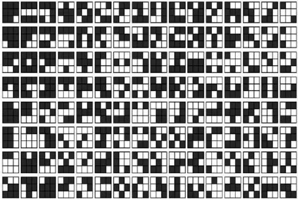
Fig. 1. List of 128 symbols also increases.
The encoding procedure of trellis modulation coding starts from setting the initial state as S0. For each input block, the encoder outputs a codeword corresponding to the input and moves to the next state. This is repeated m times. A parity symbol is then inserted for returning to the initial state S0.
This procedure is repeated to the end of the input data.
To extend the previous work, we propose a 7/9 error-correcting modulation code that has a higher code rate and error-correcting capability compared with prior modulation codes
[9-11]. In Section 2, we introduce codewords of a 7/9 error-correcting modulation code for an HDS system. This modulation code has a minimum Hamming distance greater than or equal to 2. We also explain the encoding procedure of the trellis modulation scheme that has an error-correcting capability. In Section 3, we compare the simulation results to other modulation codes — a no error-correcting 7/9 modulation code, an error-correcting 6/8 modulation code, and a conventional 6/8 balanced modulation
code, which has an equal ratio of ON to OFF pixels.
We present our conclusions in Section 4.
Ⅱ. 7/9 Error-Correcting Modulation Code
Figure 1 shows 128 symbols of the 7/9 error-correcting modulation code. The symbols have some patterns with a minimum Hamming distance greater than or equal to 2. This code performs better than a minimum Hamming distance of 2 since approximately 55–60% of codewords have a distance of 4. The encoding is done by a trellis modulation scheme for an error-correcting capability by using the symbols. The decoding of the modulation code is done by a soft-output Viterbi-algorithm (SOVA).
2.1 Codewords for the 7/9 error-correcting modulation code
The 7/9 error-correcting modulation code has 128
codewords, and each codeword is composed of a
3×3 nine-pixel array. First, we selected 256 symbols
having an odd number of ON pixel patterns and a
Input
0000010 1111110 0000101 1111110 0100101 1111111
m
⋯
Current state
State 1 State 1 State 126 State 4 State 126
Next state
State 1 State 126 State 4 State 126 State 0
Output
symbol
Symbol 2 Symbol 127 Symbol 2 Symbol 2 Symbol 35 Symbol 255 Fig. 2. Example of the encoding procedure.
Input S0 S1 S2 … S125 S126 S127
o.s. n.s. o.s. n.s. o.s. n.s.
…o.s. n.s. o.s. n.s. o.s. n.s.
0000001 0 S
01 S
02 S
0…
125 S
0126 S
0127 S
00000010 1 S
12 S
13 S
1126 S
1127 S
10 S
10000011 2 S
23 S
24 S
2127 S
20 S
21 S
20000100 3 S
34 S
35 S
30 S
31 S
32 S
30000101 4 S
45 S
46 S
41 S
42 S
43 S
40000110 5 S
56 S
57 S
52 S
53 S
54 S
5⋮ ⋮ ⋮
1111101 125 S
125126 S
125127 S
125122 S
125123 S
125124 S
1251111110 126 S
126127 S
1260 S
126123 S
126124 S
126125 S
1261111111 127 S
1270 S
1271 S
127124 S
127125 S
127126 S
127o.s.: output symbol, n.s.: next state
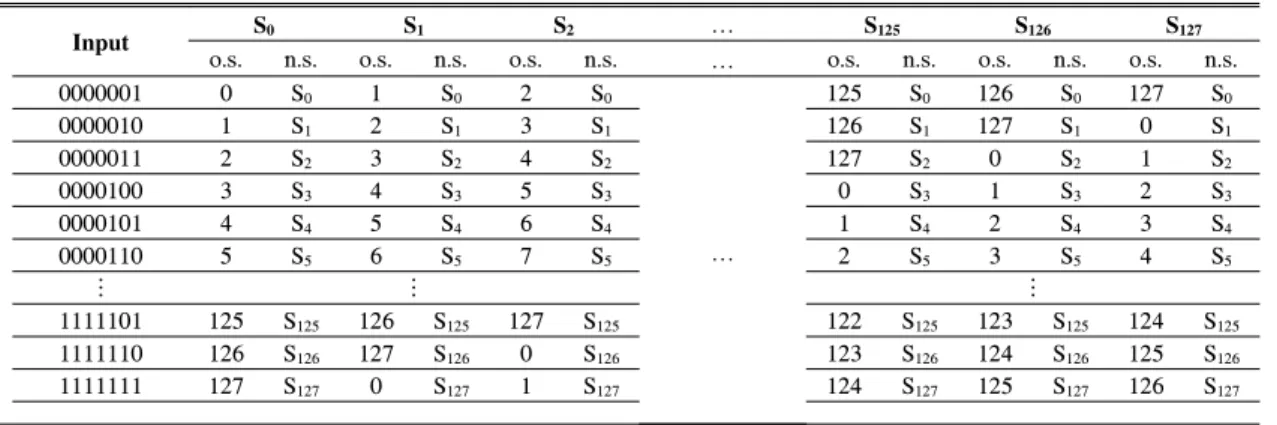
Table 1. Encoding table of modulation method (128 states).
minimum Hamming distance of 2. Second, we found a subset with a minimum distance of 4 (about 55–
60%). Third, we added the other patterns to fit the 128 codewords. This set has a minimum distance of 2 but more than half the codewords have a distance of 4. Finally, we selected 128 symbols that have some patterns with a minimum Hamming distance greater than 2 (Fig. 1).
2.2 Encoding procedure of the error-correcting modulation code
The encoding of the no error-correcting 7/9 modulation code is a simple one-to-one mapping between input and codeword (here in referred to as No ECC 7/9 code). When the modulation code is decoded, the demodulation procedure follows the minimum Euclidean distance rule
[12]. The code rate of the No ECC 7/9 code is 0.778, which is larger than the code rate of the 6/8 balanced modulation
code. The No ECC 7/9 modulation code has a Hamming distance equal to 2 or greater than or equal to 4. Meanwhile, the error-correcting 7/9 modulation coding scheme exploits the trellis modulation scheme. The trellis structure makes the shortest error event distance be greater than 3.
Because the input symbol is a 7-bit input, the trellis has 128 states. Table I shows the trellis encoding procedure. This method has a terminating parity symbol, which makes the trellis go back to S0 for a coding gain. Therefore, the real code rate becomes 7m/9(m+1). The value m is the interval between the terminating parity symbols.
The encoding procedure is as follows: First, set
the initial state to S0. Then, assign 128 symbols to
the corresponding 7-bit input so that the encoder
outputs a symbol corresponding to the input on the
current state and moves to the next state. This is
repeated m times. After that, the parity symbol is
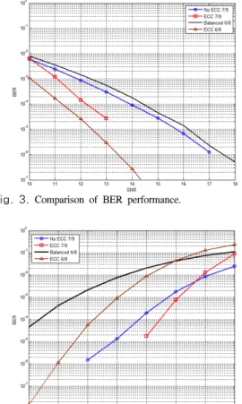
Fig. 3. Comparison of BER performance.
Fig. 4. BER performance in relation to blur.
inserted for going back to state S0. These steps are repeated until there is no input. Figure 2 shows an example of the encoding procedure.
Ⅲ. Simulation Results
3.1 Experimental environment
We evaluated each modulation code’s performances by simulation. For the HDS channel model, we used the continuous point-spread function.
(1)
where σ represents the grade of blur in the
bresultant diffracted signals. We can store a lot of data when the value of σ is large, but
binterference between adjacent symbols increases and bit error rate (BER) performance becomes worse.
We simulated 1000 data pages with a 1024×1024 array size for each page and a blur level of 1.85.
We defined the channel signal-to-noise ratio (SNR) as the ratio of signal power and the additive white Gaussian noise (AWGN) power, and the channel noise is AWGN. The detection process uses a 2D SOVA.
[13-14]We chose the interval between the terminating parity symbols to be 30 (m=30). We compared three modulation codes according to the grade of blur, SNR, misalignment level, and interval of parity symbols (m).
3.2 Simulation results
Figure 3 shows the BER performance with AWGN. No ECC 7/9 code shows a better performance than the conventional 6/8 balanced modulation code because the decoder of the No ECC 7/9 code has 9 pixels for decoding information.
In addition, the No ECC 7/9 code corrects all errors at 18 dB. However, the best performance is shown by the error-correcting 7/9 modulation code. After 14 dB, the modulation code corrects all errors.
Performance depending on the grade of blur is shown in Fig. 4. In the simulation, the SNR
condition is 15 dB. The error-correcting 7/9 modulation code showed the best performance when the blur is less than 2.1. However, as the grade of blur increases, which means worse channel conditions, the performance of the No ECC 7/9 modulation code showed better performance because under unfavorable channel conditions, the trellis scheme has an error propagation that negatively affects the performance.
Figure 5 shows the BER performance based on
the horizontal and vertical misalignment level. In the
simulation, the grade of blur is 1.85. No ECC 7/9
code shows better performance than the conventional
6/8 balanced modulation code. The BER
performance of the error-correcting 7/9 modulation
code decreased in relation to increasing
misalignment because the trellis scheme is unable to
function under bad channel conditions. Generally,
the error-correcting 7/9 modulation (ECC 7/9) code
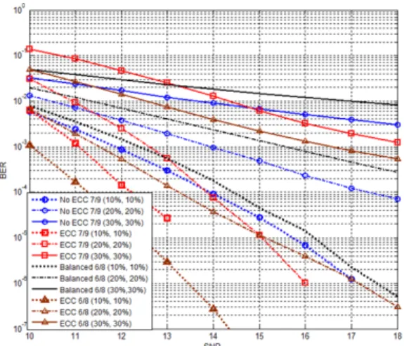
Fig. 5. BER performance with the 6/8 balanced code, 6/8 ECC modulation code, No ECC 7/9 modulation code, and 7/9 ECC modulation code in horizontal and vertical misalignments.
Fig. 6. BER performance with different parity interval (m).
performs better than the 6/8 balanced and No ECC 7/9 codes. Furthermore, if the channel condition is favorable, it outperforms the error-correcting 6/8 modulation (ECC 6/8) code. When there are (10%, 10%) misalignments, ECC 7/9 has no error at 14dB while ECC 6/8 code does not. Also, when there are (20%, 20%) misalignments, the performance graphs of ECC 6/8 and ECC 7/9 are crossed at 15dB.
Figure 6 illustrates the BER performance in relation to the interval of parity symbols. Obviously, there is a trade-off between the BER and the code rate, which means that a better BER requires a lower code rate, which is a short interval of parity
symbols. From the simulation, ECC 7/9 code has no error at 15dB when the terminating parity symbol interval is less than or equal to m=250.
Ⅳ. Conclusions
In this paper, we proposed an error-correcting 7/9 modulation code for an HDS system. Our proposed modulation code increases the code rate compared to the conventional balanced 6/8 modulation code. In addition, by using a trellis structure, error-correcting capability is improved. When the channel is favorable condition, the proposed modulation code with a trellis structure shows better BER performance than the 6/8 balanced and error-correcting modulation codes.
References
[1] R. M. Shelby, J. A. Hoffnagle, G. W. Burr, and C. M. Jefferson, M.-P. Bernal, H. Coufal, R.K. Grygier, H. Gunter, R. M. Macfalane, and G. T. Sincerbox, “Pixel matched holographic data storage with megabit pages,”
Opt. Lett., vol. 22, no. 19, pp. 1509-1511,
1997.
[2] W. Liu and D. Psaltis, “Pixel size limit in holographic memories,” Opt. Lett., vol. 24, pp.
1340, 1999.
[3] L. Hesselink, S. S. Orlov, and M. C. Bashaw,
“Holographic data storage systems,” in Proc.
IEEE, vol. 92, no. 8, pp. 1231-1280, Aug.
2004.
[4] V. Vadde and B. V. K. V. Kumar, “Channel modeling and estimation for intrapage equalization in pixel-matched volume holographic data storage,” Appl. Opt., vol. 38, no. 20, pp. 4374-4386, 1999.
[5] J. J. Ashley and B. H. Marcus, “Two- dimensional low-pass filtering codes,” IEEE
Trans. Commun., vol. 46, no. 6, Jun. 1998.[6] N. Kim, J. Lee, and J. Lee, “Rate 5/9 two-dimensional pseudo balanced code for holographic data storage systems,” Jpn. J.
Appl. Phys., vol. 45, no. 2B, pp. 1293-1296,
Feb. 2006.
[7] D. Park, M. Yoo, and J. Lee, “Tone- controllable codes for holographic data storage,” Jpn. J. Appl. Phys., vol. 49, no. 8, pp. 08KB05, Aug. 2010.
[8] D. E. pansatiankul and A. A. Sawchuk,
“Multi-dimensional modulation codes and error correction for page-oriented optical data storage,” in Proc. SPIE, vol. 4342, pp.
393-400, Jan. 2002.
[9] G. W. Burr, J. Ashley, H. Coufal, O. K.
Greygier, J. A. Hoffnagle, C. M. Jefferson, and B. Marcus, “Modulation coding for pixel-matched holographic data storage,” Opt.
Lett., vol. 22, no. 9, pp. 639-641, 1997.
[10] J. Kim and J. Lee, “Error correcting 4/6 modulation codes for holographic data storage,” Jpn. J. Appl. Phys., vol. 49, no. 8, pp. 08KB04, Aug. 2010.
[11] J. Kim and J. Lee, “Error-correcting 6/8 modulation code for reducing two-dimensional intersymbol interference,” Jpn. J. Appl. Phys., vol. 50, no. 9, pp. 09MB06, Sept. 2011.
[12] G. Yang, J. Kim, and J. Lee, “Mis-alignment channel performance of error correcting 4/6 modulation codes for holographic data storage,”
J. KICS, vol. 35, no. 12, pp. 971-976, Dec.