Performance Analysis of Spatial Multiplexing in MIMO Based Visible Light Communication System
Ratan Kumar Mondal , Nirzhar Saha*, Yeong Min Jang°
ABSTRACT
Visible light communication (VLC) is a rapidly growing area of research and applications, due to the potential and predicted high efficiency of bandwidth. One of the key challenges in VLC technology is the choice of devices which are going to be deployed VLC features. Smartphone rationally uses the most widely deployed visible light sensor i.e. image sensor in camera, which could be used to receive the intensity modulated data.
Image sensor based VLC system would be the most deployable scenario but initially the capacity was not much attractive compared with photodetector based VLC system. Here, the spatial multiplexing is proposed in MIMO based VLC system to increase the system capacity by utilizing the property of spatial separation of optical light sources in smartphone’s camera module. The active pixels of imaging plane act as the multiple receivers which could be able to use on MIMO spatial multiplexing to enhance the system performance.
Key Words : Visible light communication, MIMO, multiplexing, image sensor, LED
※ This research work is funded by the “MSIP(Ministry of Science, ICT & Future Planning), Korea in the ICT R&D Program 2013”
First author:Department of Electronics Engineering, Kookmin University, [email protected], Student member
° Corresponding author:Department of Electronics Engineering, Kookmin University, [email protected], Lifelong member
* Department of Electronics Engineering, Kookmin University, [email protected] 논문번호:KICS2013-06-248, 접수일자:2013년 6월 14일, 최종논문접수일자:2013년 9월 25일
Ⅰ. Introduction
Visible light communication (VLC) is a promising technology for indoor wireless communications. By using visible light as the transmission medium, VLC has many advantages, such as harmlessness to human health, high data rate, high security, unlicensed frequency band usage, high signal-to-noise ratio (SNR), and etc. The release of IEEE 802.15.7 MAC and PHY specifications represents a significant milestone in promoting deployment of visible light communication in short range wireless personal area networks (WPAN)
[1]. Illumination is typically provided by an array of LEDs, with levels of 400-800 lux being specified as the minimum required for sufficient illumination.
The modulation by the LEDs light must provide the dimming support for the human eye safety. In contrast, achieving high data rates is challenging
simultaneously with illuminating consistently due to
the low modulation bandwidth of the existing LED
light sources (several MHz)
[2]. Nevertheless, the
levels of illumination specified for occupation ensure
that a very high SNR is available. The availability
of a large number of high SNR channels with
sufficient bandwidth makes MIMO techniques a
promising approach both using as a diversity and a
multiplexing
[3]. The number of transmitter and
receiver are much more than the current RF MIMO
system, which provides a large number of degrees of
freedom by enabling the multiplexing gains over the
multiple channels. The potential of this paper is to
investigate the performance of MIMO spatial
multiplexing in camera based visible light
communication. MIMO is widely used in optical
communications
[4], where scattering of light and
interference creates channels that are de-correlated
from one another. This allows MIMO channels to
have higher capacity than their Single Input Single Output (SISO) without increasing the transmit power and the bandwidth.
Rest of this paper is organized as follows: the system model is described in section II. Proposed MIMO spatial multiplexing is outlined in section III.
The performance evaluation is described in section IV. Finally, we conclude the proposed scheme in section V.
Ⅱ. System Model
2.1. Transmitter and Receiver
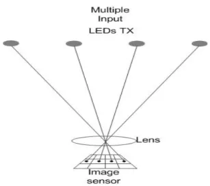
Consider the simplified imaging system as shown in Fig. 1. The transmitting panel consists of multiple arrays of LEDs and each LED or a group of LEDs can operate as a transmitter. Here the modulation is guaranteed to provide dimming support by the LED transmitters. For providing dimming support, the average light intensity must be constant over the time interval of 1ms to 10ms, during the data transmission.
For modulation, we assume that frequency shift on-off keying (FSOOK) is employed at the LEDs transmitter for the communication over the optical channel. The modulation process is similar to frequency shift keying inasmuch as there are defined mark and space ON-OFF keying frequencies for encoding bits. Consider that the imaging plane can be demodulated the bit as a two dimensional lightwave-to-digital conversion. The pixel photodetector produces a signal proportional to the incoming integrated light intensity which is then held for the scanning analog-to-digital conversion (ADC), thus establishing the frame rate of the video camera. The bit information will be acquired by sampling two times of each frame. The zero-force (ZF) equalizer has been introduced in the receiver to detect the multiple signals more accurately with less complexity.
2.2. Channel Model
Consider an optical wireless MIMO system with
optical transmit arrays (TX) and
imaging receiver (pixel area) as illustrated in Fig. 1. One
optical TX array consists of a number of optical sources and, in the context of this paper, it is regarded as a single unit which sends the same transmit signal over the optical wireless channel.
The i-th data stream is converted to an electrical current signal,
, which is given by
Fig 1 : MIMO spatial multiplexing offered by imaging plane
∞
∞ ⋯(1) where
is the symbol loaded into the k-th signal on the signal space, T is the symbol duration.
A simplified model of sampling using the Fourier series representation of the Dirac comb sampling
function can be introduced as
∞
∞
∞
∞
where
is the sampling frequency. Let us assume simplified manner that the OOK frequency is a sinusoidal at
frequency with a random phase
. If the sampling frequency is harmonic with the OOK frequency and then the OOK frequency as a harmonic of sampling frequency,
where
≥
, thus the OOK frequency is,
±
, where
≤
.
After the integration and hold the comparatively low frequency signal
would be as expressed bellow
sin
(2)
For the time being, the frequency offset has one of the two values taken from ± . For space frequency the offset frequency is zero, thus the frequency of FSOOK would be
where n is the number of sampling. For mark frequency (logic 1), let the offset frequency
±
, then the frequency of FSOOK would be
± . The detection of the mark and space can be expressed as follows [2]
sin
sin
(3)
Ⅲ. MIMO Spatial Multiplexing
Fig.1 shows, the visible-light indoor optical wireless system with four LED TXs. An imaging receiver [2] is used in place of the non-imaging devices (PD). Light propagates from the four LED TX to the receiver, and each LED TX is imaged onto an image sensor, where images may strike any pixels or group of pixels on the imaging plane, and be in arbitrary alignment with them. Each pixel on the image sensor acts like a receiver channel, and measuring the H matrix describing the optical connection between each pixel and each LED TX, allows the received signals to be separated as described in section II.
At the receiver, each pixel fulfills direct detection (DD) to produce an electrical current signal proportional to the received intensity signal.
Denoting the channel impulse response between the
i-th TX array and the j-th pixel as , thus the received signal of the j-th pixel can be written as
⊗
(4)
where
is the additive noise to the high-intensity shot noise generated by the ambient illumination which can be modeled as an additive white Gaussian noise with zero mean and
variance. Here, the input SNR of the given modulation scheme is
.The channel impulse response can be written as
′
′
′cos′ ≤ ′≤ ′
′ ′
(5)
where
′ is the imaging receiver collection area,
′
is the distance between the k-th LEDs in transmitter i and the center of the receiver collection lens,
′is the emission angle,
′is the angle of incidence of the light at the receiver, and
is the receiver field of view (FOV). Here, the SNR of i-th LED at the j-th pixel of the given modulation scheme is
.Thus the channel capacity of the MIMO system can be calculated as [3],
log
(6)
The receive vector function can be written as follows,
⋮
⋮
⋯
⋯
⋯
⋮
(8)
Here, the superscript
indicates a transpose. Also,
, which is an element of the i-th row and the j-th column in the matrix H, denotes a channel from the
j-th TX LED to the i-th RX pixel.As will be stated next, the measured MIMO
channels have mutual coupling effects. When mutual
coupling matrices in the TX and RX arrays are
defined
and
, respectively, the measured
channel matrix
His expressed as
(7)
Fig.3. BER vs. SNR performance comparison for different system scenarios.
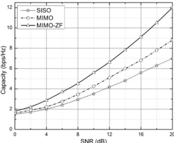
Fig. 2. System capacity performance along with SNR for different scenarios.
, where
is an
×real channel matrix which does not include mutual coupling effects. At the decision-point SNR of the k-th signal stream is obtained as
≈ (9)
where
≈
denotes the optical
power gain. The average bit error rate (BER) of the above receivers can be evaluated as
(10)
where
∞
and
will
depend on the imaging reception plane.
Parameter Value
Number of LED arrays 2 and 4
Number of LEDs per array 3600 (60x60) Distance between TX and RX 1 m Average transmitted power per LED 10/1 mW
RX’s optical resolution 640x480
RX’s diagonal FOV 68 (degree)
Focal length 2.3 mm
Frame rate at camera 30 fps
Transmission coefficient of filter 1.0
Modulation scheme FSOOK
Table 1. Simulation parameters
Ⅳ. Performance Analysis and Discussions
The performance of spatial multiplexing of MIMO based VLC system has been evaluated by representing the capacity and BER analysis. The simulation parameters are shown in table 1. Fig. 2 depicts the average capacity performance along with the SNR. As explained before, the overall data rate is increased due to the spatial separation of LEDs lightwave signal in image sensor. This figure illustrates that the capacity of
× MIMO-ZF system is increased more rapidly rather than the SISO and
× MIMO system. The capacity of the proposed system has been enhanced by increasing the number of parallel optical channel provided by the multi-array LED in TX and active pixels in RX.
Fig. 3 shows the BER versus SNR performance with three different scenarios. Usually, VLC system has very high SNR through the downlink channel using LEDs lighting, i.e., IM/DD system. As shown in the figure, FSOOK-MIMO
× system has the better BER performance than the SISO system as MIMO system improves the overall channel gain.
The channel gain is raised with the number of
multiple LEDs transmitters. It is also shown that
BER performance is improved while the receiver is
deployed ZF detection system for
× MIMO system. Thus, it could be implied that MIMO spatial multiplexing system with FSOOK modulation has an enormous profile towards the improvement of average data rate with less bit error performance.
Ⅴ. Conclusion
In this paper, we present a performance analysis of MIMO spatial multiplexing of image sensor based VLC system. Here, spatial multiplexing of MIMO operation is deployed for improving the throughput performance. Although, the parallel optical channels and proximity of pixels (i.e. receivers) may cause bit error, but the error rate is reduced by using ZF equalizer. Thus, MIMO operation with spatial multiplexing is enhanced the performance and in future image sensor based multiple access operation will deploy vastly in VLC system.
References
[1] IEEE,
Local and metropolitan area networks-part 15.7: Short-range wireless optical communication using visible light,IEEE Std 802.15.7-2011, Sep. 2011.
[2] R. D. Roberts, “Space-time forward error correction for dimmable undersampled frequency shift ON-OFF keying camera communications (CamCom),” in Proc. 2013
Fifth International Conference on Ubiquitous and Future Networks (ICUFN), pp. 459-464,Da Nang, Vietnam, July 2013.
[3] N. Letzepis, I. Holland, and W. Cowley, “The Gaussian free space optical MIMO channel with Q-ary pulse position modulation,” IEEE
Trans. Wireless Commun., vol. 7, no. 5, pp.1744-1753, May 2008.
[4] V. V. Huynh, N. T. Le, S. Choi, and Y. M.
Jang, “Collision reduction using modified Q-Algorithm with moving readers in LED-ID system,” J. KICS, vol. 37A, no. 5, pp 358-366, May 2012.
Ratan Kumar Mondal
He received his B.Sc. in Electrical and Electronic Engineering from Khulna University of Engineering
Technology (KUET),
Bangladesh in 2011.
Currently he is working towards his M.Sc. degree in the department of Electronics Engineering at Kookmin University, Korea. His research interests include visible light communication, localization, and MIMO.
Nirzhar Saha
He received his B.Sc. in Electrical and Electronic Engineering from Khulna University of Engineering
and Technology,
Bangladesh in 2011.
Currently he is working towards his M.Sc. degree in the department of Electronics Engineering at Kookmin University, Korea. His research interests include visible light communication networks, QoS management, cognitive radio networks.
Yeong Min Jang