Highly Accurate Indoor Three-Dimensional Localization Technique in Visible Light Communication Systems
Tuan Nguyen, Yeong Min Jang°
ABSTRACT
Localization, or positioning, is gaining the increasing attention of researchers around the world.
The location information, especially the indoor location, is important for navigation systems, heating and air conditioning systems, illumination adjustment, humidity control, robot service, and so on. In this paper, we propose a three-dimensional indoor localization technique using visible light. The main goal of our proposed scheme is to improve the accuracy of VLC-based indoor localization by utilizing multiple VLC transmitters. The simulation results validate the performance of our proposed scheme.
Key Words : Visible light communication, VLC, Localization, Three-dimension, Multilateration.
※ This research was funded by the MSIP (Ministry of Science, ICT & Future Planning), Korea in the ICT R&D Program 2013.
First author:Department of Electronics Engineering, Kookmin University, Seoul, Korea, [email protected], Student member
° Corresponding author: Department of Electronics Engineering, Kookmin University, Seoul, Korea, [email protected], Lifelong member 논문번호:KICS2013-06-250, 접수일자:2013년 6월 15일, 최종논문접수일자:2013년 8월 9일
Ⅰ. Introduction
Localization is one of key techniques that gain the increasing attention of researchers recent years. The location information, especially the indoor location, is important for navigation systems, heating and air conditioning systems, illumination adjustment, humidity control, robot service, and so on. Although the outdoor localization has already been well-developed using Global Positioning System (GPS), using GPS for indoor location sensing is difficult due to the poor coverage of satellites in indoor environments. To determine the indoor locations of mobile users, a number of techniques have been proposed and studied, most based on triangulation, fingerprinting, scene analysis, and proximity. There are some popular triangulation methods, including Received Signal Strength Indicator (RSSI)
[1], Angle of Arrival (AOA)
[2], Time of Arrival (TOA), and Time Difference of Arrival (TDOA)
[3].
Most of current positioning systems use Radio Frequency (RF) that faces difficulties in acquiring
accurate location coordinates due to multipath fading and non-line-of-sight (NLOS) conditions in indoor environment. Visible light is an effective solution to overcome these problems. Visible light communication (VLC) is a promising technology for wireless indoor communication in near future. VLC has many advantages, such as high speed transmission, high security, harmlessness to human health, visibility support, low power consumption, and etc
[4-6]. In 2011, VLC was already standardized in the IEEE 802.15.7 standard
[7].
In this paper, we propose a three-dimensional indoor localization technique using visible light. The main goal of our proposed scheme is to improve the accuracy of VLC-based indoor localization by utilizing multiple VLC transmitters. The simulation results validate the performance of our proposed scheme.
The rest of this paper is presented as follows.
Section II introduces VLC technology and basic
concepts of some popular indoor localization
techniques. In Section III, we represent our proposed
scheme. The simulation results are presented in
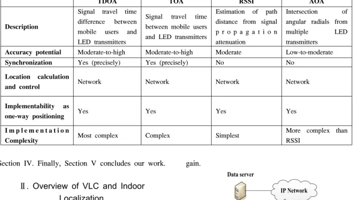
TDOA TOA RSSI AOA
Description
Signal travel time difference between mobile users and LED transmitters
Signal travel time between mobile users and LED transmitters
Estimation of path distance from signal p r o p a g a t i o n attenuation
Intersection of angular radials from multiple LED transmitters
Accuracy potential Moderate-to-high Moderate-to-high Moderate Low-to-moderate
Synchronization Yes (precisely) Yes (precisely) No No
Location calculation
and control Network Network Network Network
Implementability as
one-way positioning Yes Yes Yes Yes
I m p l e m e n t a t i o n
Complexity Most complex Complex Simplest More complex than
RSSI Table 1. Comparison of localization techniques.
Section IV. Finally, Section V concludes our work.
Ⅱ. Overview of VLC and Indoor Localization
In this section, we present an overview of VLC system model with channel model description.
Besides, some popular indoor localization techniques are represented as well.
2.1. VLC System Model
In IEEE 802.15.7 standard, there are three basic devices: Mobile user, transmitter, and single central controller called the coordinator, as shown in Figure 1. Mobile users and transmitters use visible light links to transmit or to receive data. Transmitters of a VLC network are managed by a coordinator. The IEEE 802.15.7 architecture is defined in terms of as number of layers and sublayers in order to simplify the standard. A VLC device is composed of a PHY layer, which contains the light transceiver along with its low-level control mechanism, and a MAC sublayer that provides access to the physical channel for all types of transfers.
The optical channel gain can be expressed as:
(1) where
is the transmitted optical power,
is the received optical power, and is the channel DC
gain.
Data server
Transmitter
#3
Transmitter
#1 Transmitter
#4
Transmitter
#2
Mobile user
IP Network
Coordinator
Fig. 1. Illustration of a VLC network.
Considering the line-of-sight links, the channel DC gain is defined as:
cos
× cos ≤ ≤
(2)
where m is the order of Lambertian emission, A is the photo-detector area, d is the distance between the transmitter and receiver, is the angle of irradiance,
is the angle of incidence,
is the signal
transmission coefficient of an optical filter, is
the gain of an optical concentrator, and
is the
receiver field of view (FOV).
The order of Lambertian emission m can be found from the equation:
ln cos
ln
(3)
where
is the transmitter half power angle. The gain can be determined as:
sin
≤ ≤
(4)
where denotes the internal refractive index of the optical concentrator.
2.2. Indoor Localization Techniques
Solutions for indoor positioning are becoming critical with advancement in context and location-aware technologies. Recenlty, many indoor localization systems have been developed based on different wireless measurements. In this paper we focus on representing some well-known localization techniques, including RSSI, TOA, TDOA, and AOA.
a. RSSI: RSSI methods determine the locations by estimating the distances of mobile users from some sets of measuring units, using the attenuation of emitted signal strength. This algorithm attempts to calculate the signal path loss due to propagation.
Theoretical models are used to translate the difference between the transmitted signal strength and the received signal strength into a range estimation.
b. TOA: TOA methods determine the locations based on the propagation time of signals. The one-way propagation time is measured, and the distance between a user device and the signal transmitter is calculated. To utilize TOA methods, all transmitters and receivers in the system have to be precisely synchronized.
c. TDOA: The idea of TDOA methods is to determine the relative position of the a mobile user by examining the difference in time at which the signal arrives at multiple transmitters. For each
TDOA measurement, the mobile user must lie on a hyperboloid with a constant range difference between the two transmitters.
d. AOA: AOA methods determine the locations of mobile users based on the intersection of several pairs of angle direction lines, each formed by the circular radius from a transmitter to the mobile user.
AOA methods can use only two known reference points and two measured angles to determine the two-dimensional locations of targets.
Table 1 summarizes some comparisons of these techniques.
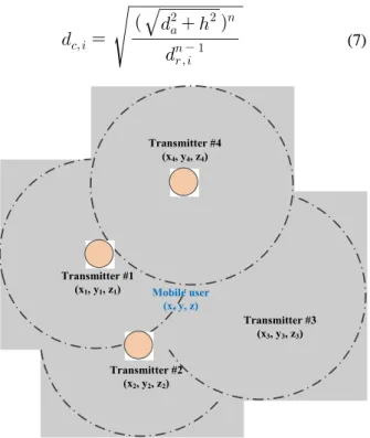
Ⅲ. Proposed Three-Dimensional Localization Scheme
The main goal of our proposed scheme is to improve the accuracy of three-dimensional localization technique with the use of multiple transmitters’ signals. In conventional trilateration and triangulation methods, to determine the locations of mobile users, these schemes use the signals of three reference transmitters. It is a fact that during its operation in a VLC network, a mobile user can receive signals from multiple transmitters, as depicted in Figure 2. The raw distance between a mobile user and a transmitter i, denoted as
, can be calculated from Equations (1)-(4):
coscos
(5)
To simplify Equation (5), the distance can be expressed as [8]:
(6)
where
is the optical constant related to the radiation intensity of LED, the photo-detector area, the concentrator gain, the optical filter gain, and the normal incidence of light into the receiver.
To reduce the error of calculation, the
compensated distance, denoted as
, can be
expressed as:
Fig. 3. Comparison of localization error.
Fig. 4. Comparison of number of localization packets.
(7)
Transmitter #1 (x1, y1, z1)
Transmitter #2 (x2, y2, z2)
Transmitter #3 (x3, y3, z3) Transmitter #4
(x4, y4, z4)
Mobile user (x, y, z)
Fig. 2. Three-dimensional localization technique.
where
, h, and n are, respectively, the distance between two adjacent transmitters, the height of a mobile user calculated from ground, and the normalized factor.
We denote the three-dimensional location of a mobile user as
. If the mobile user receives signal from k transmitters, then the mobile user’s location can be calculated using a RSSI algorithm:
⋮ ⋮ ⋮ ⋮
(8)
where
, with
… , is the coordinate of transmitter I.
We assume all the transmitters have the same height calculated from ground, so:
…
(9) By this assumption, we only need to calculate the x coordinate and y coordinate of the mobile user first from Polynomial (8), and the z coordinate can be determined based on the values of
. Besides, by using every three equations from Polynomial (8), we can get one possible root of the location of mobile user. With k equations of Polynomial (8), the number of possible roots, denoted as r, can be:
(10) The final determined location
of the mobile user should be the combined result of all the possible roots. This final determined location can be calculated as:
(11)
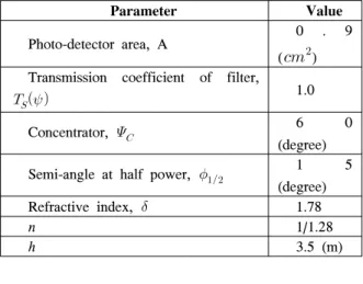
Parameter Value
Photo-detector area, A 0 . 9
(
) Transmission coefficient of filter, 1.0
Concentrator, 6 0
(degree) Semi-angle at half power,
1 5
(degree)
Refractive index, 1.78
n 1/1.28
h 3.5 (m)
(12) where
is the value of a possible
root.
The mean relative localization error can be calculated by Equation (12), where
is the
location sample, E is the total number of location samples, and
is the real location value of
sample.
Ⅳ. Performance Evaluation
In this section, we evaluate the performance of our proposed scheme regarding location error percentage.
Table 2 shows the assumption of parameters used for our experiment.
Table 2. Parameters assumption.
Figure 3 shows the simulation results of localization error. The increase of reference transmitters used for our localization technique results in the decrease of localization error. However, the increase of reference transmitters brings about the increase of number of localization packets.
In Figure 4, the impact of number of reference transmitters on the number of localization packets is taken into account. In this experiment, the number of transmitters in VLC system is set to 100. When the number of reference transmitters used for localization technique is 8, the number of localization packets is
4 times more than those of 3-reference-transmitter case.
Ⅴ. Conclusions
Visible light communication is a promising technology for future wireless indoor communications. With the use of visible light, the quality of not only data communication but also many other purposes can be improved efficiently. In this paper, we propose a three-dimensional indoor localization technique using visible light. The main goal of our proposed scheme is to improve the accuracy of VLC-based indoor localization by utilizing multiple VLC transmitters. The simulation results validate the performance of our proposed scheme.
References
[1] S. Mazuelas, A. Bahillo, R. M. Lorenzo, P.
Fernandez, F. A. Lago, E. Garcia, J. Blas, and E. J. Abril, “Robust indoor positioning provided by real-time RSSI values in unmodified WLAN networks,” IEEE J. Sel.
Topics Signal Process., vol. 3, no. 5, pp.
821-831, Oct. 2009.
[2] M. Alsehaili, S. Noghanian, D. A. Buchanan, and A. R. Sebak, “Angle-of-arrival statistics of a three-dimensional geometrical scattering channel model for indoor and outdoor propagation environments,” IEEE Antennas
Wireless Propag. Lett., vol. 9, pp. 946-949,Sep. 2010.
[3] S. Jung, S. Hann, and C. Park, “TDOA-based optical wireless indoor localization using LED ceiling lamps,” IEEE Trans. Consum. Electron., vol. 57, no. 4, pp. 1592-1597, Nov. 2011.
[4] T. Komine and M. Nakagawa, “Fundamental
analysis for visible-light communication system
using LED lights,” IEEE Trans. Consum.
Electron., vol. 50, no. 1, pp. 100-107, Feb. 2004.
[5] T. Nguyen, M. Z. Chowdhury, and Y. M. Jang,
“Flexible resource allocation scheme for link switching support in visible light communication networks,” in Proc. Int. Conf. ICT Convergence
(ICTC’12), pp. 145-148, Jeju Island, Korea, Oct.2012.
[6] H. L. Minh, D. O’Brien, G. Faulkner, L. Zeng, K. Lee, D. Jung, Y. Oh, and E. T. Won,
“100-Mb/s NRZ visible light communications using a Postequalized white LED,” IEEE
Photonics Technol. Lett., vol. 21, no. 15, pp.1063-1065, Aug. 2009.
[7] IEEE, IEEE standard for local and metropolitan
area networks - Part 15.7: Short-Range Wireless Optical Commnucation Using Visible Light,IEEE 802.15.7, Sep. 2011.
[8] H.-S. Kim, D.-R. Kim, S.-H. Yang, Y.-H. Son, and S.-K. Han, “Inter-cell interference mitigation and indoor positioning system based on carrier allocation visible light communication,” in Proc. 5th Int. Conf. Signal
Process. Commun. Syst. (ICSPCS’11), pp. 1-7,Hawaii, U.S.A., Dec. 2011.
Tuan Nguyen
He received his B.Sc. in
Electronics and
Telecommunications from Hanoi University of Science and Technology (HUST), Vietnam in 2011. Currently he is working towards his M.Sc. degree in the department of Electronics Engineering at the Kookmin University. His research interests include convergence networks, VLC networks, LED-ID networks, localization, and QoS provisioning.
Yeong Min Jang