Received: June 2, 2017 Revised: June 9, 2017 Accepted: June 9, 2017
Copyright © 2017. The Korean Academy of Oral &
Maxillofacial Implantology
This is an Open Access article distributed under the terms of the Creative Commons Attrib- ution Non-Commercial License (http://creative- commons.org/licenses/by-nc/4.0/) which permits unrestricted non-commercial use, distribution, and reproduction in any medium, provided the original work is properly cited.
pISSN : 1229-5418
Implantology 2017; 21(2): 110-127 https://doi.org/10.12972/implantology.20170009
eISSN : 0000-0000
OPEN ACCESS
밀폐형 자외선 광조사 임플란트의 공진 주파수 분석과 조기부하: 증례보고
설현우1, 박규화2*, 허정욱3, 손병섭4, 김승수5
1
중앙대학교병원 치과보철과
2
프라임치과
3
굿윌 치과병원
4
에스플란트 치과병원
5
미유치과
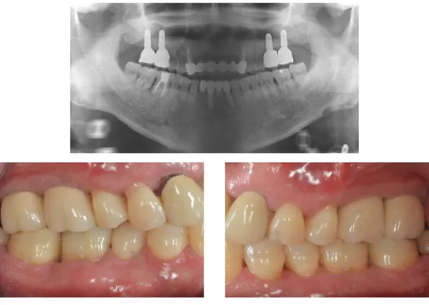
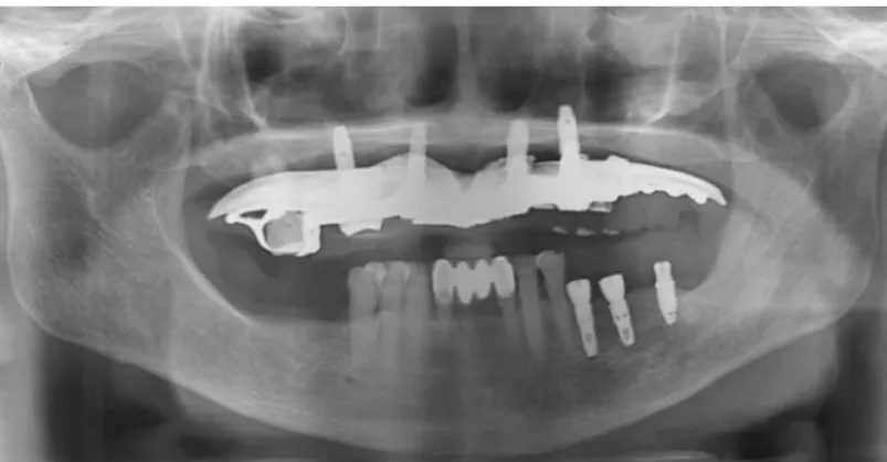
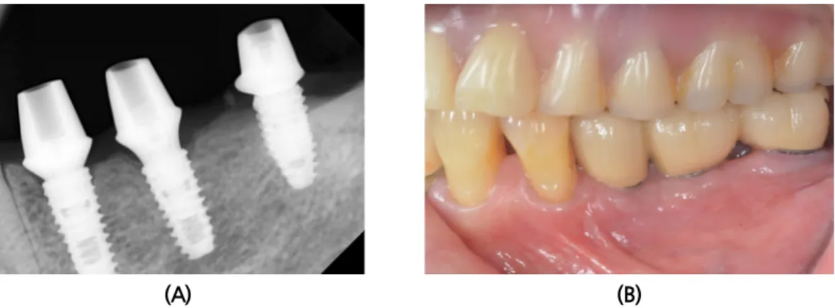
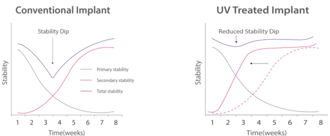
Resonance Frequency Analysis and Early Loading of Implants with Sealed UV Treatment System:
Case Reports
Hyon-Woo Seol
1, Kyou-Hwa Park
2*, Jeong-Uk Heo
3, Byeong-Sup Sohn
4, Seung-Soo Kim
51
Department of prosthodontics, Dental Center, Chung-Ang University Hospital, Seoul, Korea
2
Prime Dental Clinic, Seong-Nam, Korea
3
Good Will Dental Hospital, Pusan, Korea
4
S-plant Dental Hospital, Seoul, Korea
5