†Corresponding author(Division of Mechanical and Energy System Engineering, Korea Maritime University, E-mail:[email protected]) 1 Mechanical Engineering Korea Maritime University
2 Associate Ship & Oscean R&D Institute Daewoo Shipbuilding & Marine Engineering CO.,LTD.
3 Electric Motor Research Center Korea Electrotechnology Research Institude 4 Graduate School, Division of Mechanical Engineering, Korea Maritime University
Active Vibration Control of a Plate Using TMS320C6713DSK
Hyeung-Sik Choi1⋅Sam-Sang You†⋅Jae-Gwan Her2⋅Hae-Yong Seo3⋅Ngoc-Huy Tran4 (Received September 14, 2010; Revised December 1, 2010; Accepted January 14, 2011)
Abstract:This paper deals with the experimental study of the vibration suppression of the smart structures. First, a new high-speed active control system is presented using the DSP320C6713 microprocessor. A peripheral system developed is composed of a data acquisition system, A/D and D/A converters, piezoelectric (PZT) actuator/sensors, and drivers using PA 95 for fast data processing. Next, the processing time of the peripheral device is tested and the corresponding test results are provided. Since fast data processing is very important in the active vibration control of the structures, achieving the fast loop times of the control system is focused. The control algorithm using PPF in addition to FIR filter is implemented. Finally, numerous experiments were carried out on the aluminum plate to validate the superior performance of the vibration control system at different control loop times.
Key words:Active vibration control, DSP, PZT actuator/sensor, PPF control
1. Introduction
Recently, there has been widespread interest in the active vibration control system. Owing to the performance of the improved piezoelectric devices, a great deal of attention has been paid on the research and development of high-speed active control system integrated with PZT sensors/
actuators and controllers. There have been a large number of theoretical papers for vibration control of the cantilever beam and thin-plate beam.
However, few papers have considered the active control system with fast processing microprocessors, experimentally.
A control system using VMEbus processor was presented for vibration control of the thin-plate [1].
Also, there has been an experimental result on real-time control for a rectangular steel plate
incorporated with ADSP21062 EZKI and EZ_ANC II digital-signal-processing (DSP) [2]. In addition, Chu et. al. had designed a simulator using real-time active controller with TMS320C40 DSP board [3].
The active controller has been proposed for cylinder shell structures, integrated with PZT driver and TMS320C30 DSP using PPF controller and filtered-x LMS controller [4]. Further, the active controller for steel plate with 340x300x0.5 [mm3] in dimension has utilized DSP320C30 DSP featuring multi- adaptive feed-forward control inputs [5]. A DSP controller and selected control algorithms are implemented to a complex autoparametric
‘‘L-shape” beam system to compare numerical and experimental results. Detailed analysis for the NSC system is carried out [6]. A novel distributed sensing and actuation approach for actively
suppressing vibrations within flexible link manipulators has been presented where UPM-2405 power amplifier, which is interfaced with a Quanser Q8 (8-channel) control board embedded in a host PC has been applied [7]. Active vibration control using modal controllers has been successfully implemented on simple structures such as beams and plates. A stand-alone DSP having sampling frequency of 20 kHz is applied and the input channels to the DSP are connected via a sensor amplifier to four PVDF film sensors [8].
In this study, to prove the performance of the fastest controller experimentally, a new active control system is developed adopting fast microprocessor in TMS320c 6713 series with peripheral devices; high-speed A/D and D/A converters, and a new PZT driver. For the control algorithm, a PPF control with FIR filter is applied.
2. Design of the control system
In PZT materials there is coupling between the electrical and mechanical constitutive relationships.
Note that PZT materials generate an electric charge proportional to applied stress, which makes them a natural sensor. Conversely, PZT materials can be effectively used as an actuator, as they deform when an electrical charge is applied. As a result, they can be used in actuation and sensing.
The general constitutive equations of linear-piezoelectric materials describe a tensor relation between mechanical and electrical variables in the form [4]
(1)
(2)
where is the mechanical strain, is the mechanical stress, is the electrical field, is the electrical displacement, is the mechanical compliance of the material measured at zero
electric field ( ), is the dielectric permittivity measured at zero mechanical stress ( ), and is the piezoelectric coupling between the electrical and mechanical variables.
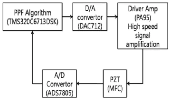
Referring to Figure 1, an active control system is composed of a high-speed plus relatively low-priced DSP320C6713 processor whose processing speed is 1500 [MPLOPS]. In other words, its processing speed is 27 times faster than the DSP320C30 processor, and its detailed specifications are described in [9]. Also, an interface system has been developed based on A/D and D/A converters providing extremely high-speed processing and resolutions. More explicitly, the complete actuator system is consisted of the PZT driver and elements: the PZT driver is intended to amplify control signals from the DSP board up to
±400 [V] for the actuating elements, and the PZT sensor detects the amplitude of vibration and transmit it to the DSP control board via the A/D converter. The MFC actuator/sensor used is NASA M8557 S1 type, and its specification is described in [10].
In this study the interface system to communicate with external devices includes A/D converter for sensing signals from PZT device and D/A converter for receiving signals from PZT actuator driver. They are ADS7805 and DAC712 chips charactering 16 bit resolutions, respectively.
Figure 3 depicts the I/O interfaces ensuring communication with the main controller, A/D and D/A converters. The PZT driver amplifies control signals of the main controller to execute active control action up to PZT driving voltage. In the study, a PA97 commercial driver manufactured by APEX Corp. have been utilized as the actuator amplifier.
Now, the structure and configuration of the complete control system are shown in Figure 1 and in Figure 2. The PZT sensor is connected to
the input port of the A/D converter wired to the DSP chip whose data and address buses are further connected to data ports of the D/A converter. Analog output ports of the D/A converter are connected to the input ports of the PZT actuator amplifier, and the output ports of the non-inverted amplifier are now linked to the input ports of the PZT actuator amplifier.
Figure 1: Block diagram of controller
3. Performance test of control system
When sensors/actuators are arranged in a collocated way, the so-called positive position feedback (PPF) is extensively used in practice. The modal control structure is described in Figure 2 where the input is η and the output is .
Figure 2: Structure of the closed loop system
In the framework of the PPF design methodology [11,12], the system and control structure for the single-input single-output (SISO) are described modal equations as
(3)
(4)
where
: modal coordinate of the plate Ω : natural frequency of the plate
: modal coordinate of the controller
: damping coeficient of the plate
f : natural frequency of the controller
f : damping coeficient of the controller g : feedback control gain
Using the modal dynamic Equations (3) and (4), the transfer functions of the plate in equation (5) and the controller in Equation (6) are expressed as
(5)
(6)
1 1 2
+
= − z z s T
s (7)
where, is sampling rate for the compensated circuit (or controller).
The use of a digital control system requires the transformation of the time-continuous equation into its time-discrete form. Substituting (7) into (6) using bilinear transform leads to
0 1 2
0 1 2
) 2
( z az a
b z b z z b
H + +
+
= +
(8)
where,
Ω +
−
=(4/ 4 / 2)/
0 Ts f f Ts f
a ζ ω ω
Ω
−
=(2 2 8/ 2)/
1 f Ts
a ω
Ω
= 2/
0 f
b ω , b1=2ω2f/Ω Ω
= 2/
2 f
b ω
2
2 4 /
/
4 Ts + ζfωf Ts+ωf
=
Ω .
Then the discrete form for the control algorithm (8) is described in a simple iterative procedure as
(9) where represents the sampled output of the sensor and is the calculated control input.
It is known that feedback control using PPF compensator will accomplish the addition of damping to selective modes [13]. Note that the PPF controller is a highly damped second order low-pass filter that can be tuned to resonate at a flexible structure's natural frequency, much like a tuned mass damper [10]. This compensator could be tuned such that the natural frequency of the compensator (or filter) corresponds to the excitation frequencies, rather than natural frequencies of the structure, and thus provide effective vibration cancellation. At low frequencies this controller adds flexibility and at high frequencies it adds stiffness to the structure.
Moreover it also tends to split the vibration modes.
3.1 Sensing test of PZT device
As illustrated in Figure 3, M8557 PZT actuator/sensor [10] is glued to the rectangular aluminum plate supported by the two ends. The plate thickness is 1.5 [mm], and its overall width is 210x400 [mm2] in dimensions. The signal of the PZT sensor was measured by the 400 [MHz]
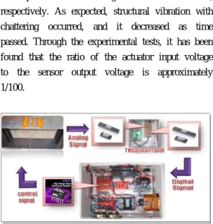
digital oscilloscope, and ±5 [V] test input signal with 10 [Hz] period was applied using the function generator, and then it was amplified to ±100 [V], and the output sensor signal from the PZT was measured as ±2 [V] as shown in Figure 4.
The amplified test signal was applied to the PZT actuator, and the voltage signal of the sensor on the vibrated plate was measured. At the rising and falling edge of the step input pulses, the negative
and positive sensor signals were measured, respectively. As expected, structural vibration with chattering occurred, and it decreased as time passed. Through the experimental tests, it has been found that the ratio of the actuator input voltage to the sensor output voltage is approximately 1/100.
Figure 3: Test bed for vibration control system
Figure 4: 100 [V] test input with 10Hz (50ms)
3.2 Performance test of drivers
The DSP processor receives the digital signal converted from the analog sensor signal by the A/D converter. According to the control algorithm, the control signal is converted into the analog signal through the D/A converter, which is amplified and put into the PZT actuator. Note that the PZT actuator requires high voltage for actuation. A credible commercial driver PA97 was applied for amplifying the input signal as illustrated in Figures 4 and 5 where the test results of the drivers are presented. For the performance test of the driver, a voltage of 5 [V]
from the function generator was applied to the bridge driver as a step input and amplified output signals were generated in Figure 5 and 6. Also, the processing time from the sensor to the amplified signal of the devices was tested in Figures 5 and 6 where the lower and upper ones represent the sensor signal and the amplified signal, respectively. Figure 6 clearly gives the delay time. 5 [V] clock pulse with 5 [kHz] using the function generator was applied to the A/D converter. Each row line in the upper plot represents 50 [V] and in the lower describes 5 [V]. The processing time between A/D converter and the amplifier took 24.5 [㎲], where A/D conversion, D/A, and amplifier took 10 [㎲], 2 [㎲], and 12.5 [㎲], respectively. The amplifier has 8 [V/㎲] rate such that it took 12.5 [㎲] in amplifying the voltage up to 100 [V], which is fast enough for active vibration control. Here, the processing time can be reduced by adapting faster peripheral devices.
Figure 5: Amp output at 1 [kHz]]
Figure 6: Amp output at 5 [kHz]
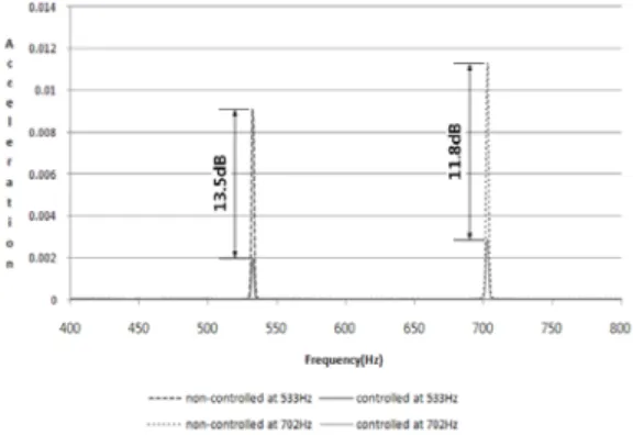
3.3 Implementation of the active vibration control Experiments to test the performance of the developed control system, which is intended to reduce the vibration mode of the aluminium plate have been conducted. Six MFC actuators composed of four M-8528 and two M-8507 were applied on the plate. Through the mode tests of the plate, it is observed that the frequencies of first and second modes are 533 [Hz] and 702 [Hz] using FFT analyzer, respectively. The control system composed of the TMS320c6713 DSP controller and the interrelated Matlab simulink set up as in Figure 7. Using this system, The PPF control algorithm was applied in addition to the FIR filter as in Figure 8. The PPF control algorithm is to reduce the first and second mode of the natural frequency and the FIR filter is to get rid of initial noise signals as shown in Figure 9. By applying the control algorithm using simulink, the vibration modes of the plate are reduced as in Figure 10. In the first mode, about 13.5 dB and in the
Figure 7: Matlab simulink modeling
Figure 8: PPF Control & FIR Filter
second mode, 11.8dB were decreased in vibration amplitude.
The TMS320C6713 processor is about 27 times faster than TMS320C30 chip which has been used in many active vibration control tests so far.
Experiments were performed by varying the loop time of the controller. Experiments by increasing loop time every 10㎲ from 40 to 250 ㎲ were performed. In Figure 11, results are presented.
Consequently, it is identified by the fact that the active control system shows better vibration reduction performance with faster loop times.
Figure 9: Comparing signal output
In the FIR, linear phase FIR filter algorithm was applied where difference equation of FIR filter [14] is expressed as
0 1 1
1 1
0 0
( ) ( ) ( 1) ( ( 1))
( ) ( ) ( )
M
M M
k
k k
y n b x n b x n b x n M b x n k h k x n k
−
− −
= =
= + − + − −
=
∑
⋅ − =∑
⋅ −L
(10)
where = h(k) for 0 ≤ k ≤ M - 1
where bk is the coefficients and h(k) is impulse response. The FIR filter has linear phase if it satisfies the following condition.
( ) ( 1 )
h n = ±h M− −n (11)
for 0≤ ≤n M−1
Figure 10: Vibration reduction at the natural frequency
Figure 11: Reduction of vibration by changing loop time
4. Conclusions
In this paper, a new high-speed active control system with the PPF in addition to FIR filter has been developed to suppress the vibration of the rectangular plate. The complete control system using PZT sensor/actuators incorporates the fastest DSP320C6713 microprocessor and peripheral devices such as A/D and D/A converters, and amplifier. Using the developed system, the processing time of the processor and peripheral devices has been tested for the fast speed of the loop times. It is observed that the overall processing time was fast enough to control the vibration mode of the prepared aluminum plate.
Additional experiment has been conducted with different loop times. In particular, the PPF control algorithm with the FIR filter has been applied to
reduce the specific vibration modes of the plate and noises, and the test results with different loop times have been provided.
As experiment results, firstly, faster loop time shows better results in vibration suppression.
Secondly, the proposed PPF control algorithm with FIR filter showed the good vibration suppression performance. Accordingly, it is ensured that the proposed control scheme using DSP320C6713 would be a prospective control system in active vibration control of structures.
Acknowledgement
This study was supported by Research Grant from the Underwater Vehicle Research Center of Defense Acquisition Program Administration and Agency for Defense Development, Korea. This financial support is gratefully acknowledged.
References
[1] M. Strassberger and H. Waller, “Active noise reduction by structural control using piezo-electric actuators”, Mechatronics, vol. 10, pp. 851-868, 2000.
[2] S. D. Snyder and S. G. Hill, “Acoustic- centric modal filter deign for active noise control,” Control Engineering Practice, vol. 12, pp. 1055-1064, 2004.
[3] S.Y. Chu, T.T. Soong, and A.M. Reinhorn,
“Real-time active control verification via a structural simulator”, Engineering Structures, vol. 24, no. 3, pp. 343-353, 2002.
[4] H. Sumali, Demonstration of active structural acoustic control of cylinders, MS. Thesis, VPI and State University, Blacksburg, VA, USA, 1992.
[5] Y. S. Kim, C. Lee, and I. S. Kim, “Hybrid technique for active vibration control of plate using piezoceramic actuators/sensors,” Korean Soc. Noise and Vibration Engr.”, vol. 10, no.
6, pp. 1048-1058, 2000.
[6] J. Warminski, M. Bochenski, W. Jarzyna, P.
Filipek and M. Augustyniak, “Active suppression of nonlinear composite beam vibrations by selected control algorithms”, Commun Nonlinear Sci Numer Simulat, 2011(in press).
[7] K. Gurses, J. B. J. Buckham and E. J. Park,
“Vibration control of a single-link flexible manipulator using an array of fiber optic curvature sensors and PZT actuators”, Mechatronics, vol.19, pp. 167–77, 2009.
[8] S. Hurlebaus, U. Sto¨bener b and L. Gaul,
“Vibration reduction of curved panels by active modal control”, Computers and Structures, vol. 86, pp. 251–57, 2008.
[9] Webpage at http://dspvillage.ti.com.
[10] Webpage at http://www.smart-material.com [11] K. M. Kwak, “Realization and experiment of
digital PPF controller using micro-controller”, Proc. of KSNVE Conf., pp. 148-152, 2003.
[12] J. L. Fanson and T.K. Caughey, “Positive position feedback for large space structures”, AIAA Journal, vol. 28, pp. 717-724, 1990 [13] A. Baz, S. Poh, and J. Fedor, “Independent
modal space control with positive position feedback," J. of Dyn. Syst. Meas. and Contr.,”
vol. 114, pp. 96-103, 1992.
[14] Rulph Chassaing, Digital signal processing and application with the C6713 and C6416 DSK, Wiley, 2005.
Author Profile
Hyeung-Sik Choi
He received MS at the Dept. of Mechanical Engineering in University of South Carolina at 1989.5, and Phd at the Dept. of Mechanical and Aerospace Engineering in North Carolina State University 1993.2. He is performing research in the area of unmanned underwater robot, humanoid robot, exo-skelleton, industrial robots, and control system.
Sam-Sang You
He is a Professor at the Division of Mechanical and Energy Systems Engineering, Korea Maritime University, Korea. He received an MS in Mechanical Engineering from University of Wisconsin-Madison in 1990 and a PhD in Mechanical Engineering from Iowa State University, USA in 1994. His research areas of interest include underwater vehicle dynamics, robust controller design, and MEMS.
Jae-Gwan Her
He received his B.A Degree in 2008 from Korea Maritime University. He is currently working on a master's degree from Korea Maritime University. His interests are in applications of active vibration control and control systems.
Hae-Yong Seo
He received his B.A Degree in 2009 from Korea Maritime University. He is currently working on a master's degree from Korea Maritime University. His interests are in applications of active vibration control and control systems.
Ngoc-Huy Tran
He was born in Ho Chi Minh city, Vietnam in 1984.He received B.E degree from Ho Chi Minh city University of Technology, Vietnam in 2008. He is currently studying master's degree from Korea Maritime University, Busan, Korea, in 2010. His interests are in applications of active vibration control and control systems.
![Figure 5: Amp output at 1 [kHz]]](https://thumb-ap.123doks.com/thumbv2/123dokinfo/4839620.282987/5.786.85.702.499.982/figure-amp-output-at-khz.webp)