25
압전 센서와 액츄에이터를 이용한 단순지지 평판의 능동 진동제 어 一 I. 이론
Active Vibration Control of a Simply Supported Plate with Piezoelectric Sensors and Actuators — I. Theory
노용래*
*산업과학기술연구소 접수일자: 1992. 3. 3.
(Yongrae Roh* )
요 약
압전 센서와 액츄에이터를 이용한 단순지시 평판의 진동체어에 관해 이론즈] 고찰을 하였다. 적질한 센서, 액츄에 이터의 운동방정식을 구한 후 평판의 운동 방정식과 결합해 능동 진동제어 시스템을 구성하였으며, 외력과 제어력 의 복합 영향을 고려한 평판의 진동 진폭반응을 해석하였匸土 본 방법의 효용성을 보이기 위해 집중 응력과 압전구동 기에 의한 모멘트의 두가지 외력에 대한 진동반응을 수치해석 하였으며, it 결과 압전 센서와 액츄에이터로써 구조 물의 외력에 대한 진동반응을 효율적으로 감소시킬 수 있었匸]■. 본 연구에서 고찰된 방법은 임의의 외력 조건과 제어 알고리즘에 적용이 가능하다.
Abstract
Undesired vibratory motion of a simply supported plate is controlled with piezoelectric sensors and actuators. Appropriate dynamic equations of the sensor and actuator are derived and coupled with the dy
namic equation of the plate for the construction of an active feedback vibration control system. Analytic solutions are obtained for amplitude response of the plate, reflecting the combined effect of external driving forces and piezoelectric control moments. Numerical examples are presented to illustrate the effectiveness of this approach for two types of external forces, i.e. a concentrated point load and a piezoelectric plate driver.
Calc니lation res니Its show that the sensors and actuators can be efficient tools to mitigate the sensitivity of the structure to external sources of vibration, The method investigated m this work is applicable to arbitrary external loading conditions and control algorithms.
I , Introduction
There are, in general, two categories of te chniques available to vibration control speci
alists: (1) passive method in which the impressed force does work m the damper and (2) active method in which an auxiliary mechanism coun teracts the effect of the undesirable force[l].
The control technique has to be efficient and should not increase the size and weight of the components substantially. This paper concern^
26 韓國횹馨學會誌 11 卷 3 號(1992) the active vibratidn control system that r•이y in
its operation on piezoelectric sensors and act
uators. Such systems have been experimentally demonstrated to be effective in suppressing the vibration of simple structural elements like one dimensional rectangular beams[2]. The effective
ness of these systems is consolidated by the light weight, high force and low power consumption capabilities of the sensors and actuators. These features render this method an attracive ap
proach for controlling structural vibration of higher orders.
This paper is concerned with the use of bonded piezoceramic sensors and actuators to actively control vibration in a two dimensional structural dynamic system, a simply supported plate. Defor
mation of the bonded piezoceramic transducer results in an electrical voltage in the sensor de
tection unit This signal is conditioned by control circuits adopting various algorithms. The processed signal is used as an input to bonded piezoelectric actuators located at selected positions, and the actuators transmit mechanical energy to the flexible structure. Instantaneous feedback circulation of input signal to controlling energy can reduce overall vibration response of the plate to external forces. A wide selection of feedback algorithm is available in connecting the sensed signal to the actuator[3, 4], In deciding on the algorithm, one must weigh the ease of im
plementation of feedback against the desirability of control method. A strategy offering simple im
plementation is direct feedback control, whereby the control force at a given point depends only on the state at the same point. In this st니dy, there
fore, the direct feedback technique is pursued in favor of the simplicity.
This work investigates theoretical aspects of the active vibration control of a simply supported plate and performs analytic derivation of its am
plitude response to external forces. The deri vation is very general-. It can accommodate arbi
trary external loading conditions as well as arbi- tra丁 number and location of piezoelectric sensor 'actuator pairs. Based on the direct
feedback control algorithm, numerical examples are presented to illustrate effectiveness of the method for concentrated point loads, piezoelectric plate drivers, and their combination. Calculation results show that the sensors and actuators can effectively reduce the vibration amplitude of the structure responding to external forces. This ap
proach is applicable to any control algorithm.
II. Piezoelectric sensors and actuators in a simply s냐pported plate
Ideal sensors or actuators for vibration sup
pression would be electrically powered, highly ef
ficient, light, and would have a high bandwidth.
The high bandwidth requirement allows a design
er to constr니ct a closed loop system without re
gard to sensor and actuator dynamics. Two types of piezoelectric materials are available to choose from, piezoelectric ceramics and pie
zoelectric polymers, and they each have specific advantages and disadvantages. Both types are electrically powered, are low in mass, and have high bandwidth. Principal advantages of the cer
amics are higher -electromechanical efficiency, and low voltage operation capability. That of the polymers is the ease of casting the material into an arbitrary surface shape[5]. This study adopts the piezoceramics, PZT, as both the sensor and actuator materials.
Piezoelectric niaterial is an inherent electro
mechanical transducer. An electric field causes it to strain by an amount proportional to the strength of the applied field. The actuator is arranged so that a voltage applied to the elec
trode surfaces causes the ceramic to expand or contract depending on the polarity of the electric field. Simila디y, the bending of the plate stresses the sensor ceramic which in turn produces a volt age to be measured. When the plate is bent by external forces such as initial boundary conditions or harmonic loading, the sensor responds to the applied stress. Above discussion can be sum
marized m the following two sets of constitutive equations of a piezoelectric material[6].
압전 센서와 액츄에이터를 이용한 단순시지 평판의 능동 신동제어一I. 이론 27
S-s^T + gDe S = sEeT + dEe
Ee = - g T + T De
De=dT + cTEe (1)
where S is mechanical strain, T is mechanical stress, S* is compliance measured at constant De field, SEe is compliance measured at constant Ee field, g 겨nd d are piezoelectric stress and StTcHii constants, De is electrical displacement fi이d, Ee is electric field, eT is permittivity measured at constant stress field, and 阡 is impermittivity measured at constant stress field. PZT has the hexagonal 6mm crystal symmetry after poling.
When the crystal Z axis is configured to be a piezoelectric
(a) plate with piezoelectric sensors and actuators on
poling direction and the other two crystal axes ly
ing on the transversal isotropic basal plane, its piezoelectric stress constant matrix consists of three nonzero independents components as follows:
[
g:U g32 g33 0 0 0 0 0 0 g” 0 gi:0 0 0 > 000 (2) where gis=g24 and g.3i=g32. The same argument applies to the other set of piezoelectric constants d.Main idea in the use of piezoelectric sensors and actuators for active vibration control is to measure and to cancel the bending moment at specific points of the structure. Figure 1 shows the structural model with the sensor and actuator on. To avoid residual spillover effects, the PZT sensor is placed in parallel with the actuator, collinear placement. For the detection purpose, the sensor needs not be large. It is made so small that it is regarded as a point sensor with regard to the vibration modes of interest in this study.
The actuator takes the form of a bimorph. The well-known theory of piezoelectric devices says that a bimorph actuator connected in parallel can produce four times more deformation than a unimorph does[기.
Assuming that the stress at the mid-thickness of the PZT film is the sensor stress o-s, the sensor responds to the planar curvature of the plate[8].
From Eq.l, a sensor equation corresponding to Fig. 1-b is
Vs = tb Es
=ts g3i(Js. (3)
In Eq. 2, g:"=g35 g"=() and the PZT sensor can not respond to surface shear stresses. By lin
earity.
Ag 1. Lateral view oi a simpiy suppoiteu plate with piezoelectric sensors and actuators on. t、is thickness of the sensor, ta is thickness of the actuator, tp is thickness of the plate, and ti)is thickness of the neutral plane
From the plate theory|_9 ].
— —v 7 寥三표+ v 표 ) I c
* …YM * ,旗wV 丿 I z--0.5t- +
28 韓國音•響學會誌
11卷3號(1992)
= -Yss(O.5ts + tp-to)(gy + vs-^)
aSx=-YsS(O.5ts + tp-to)(fF + vs-g£)⑸
where w is plate displacement, vs Poisson's ratio of 나io piezoelectric sensor, and Ys 나冶 effec- tive Young s mod니us of the sensor, i.e. plane stress version Ys = 况 the common elas
tic constant Y;, respectively, to is the distance of the neutral axis from the bottom of the plate. It is calculated by considering the force balance in the X axis of the composite plate as
[plate "px dz + "ensor ^sx dz = o (6)
where ^px is the X axis stress in the plate and (Lx is the X axis stress in 나le sensor. When the
°x in Fig. 1 is assumed to vary linearly with the distance z from the neutral axis, Eq. 6 turns out to be
「Pf ft$+tpT0
J-to YpZdz+Jtp-t„ Y/A" ⑺
which yields
to = Ypt2p+ 丫成$ + 2Y$tpts
—2(YptP+Ysts)~ ⑻
where Yp is the effective Young's modulus of the plate. Therefore when the Eqs. 3, 4, and 5 are combined together, the voltage Vs produced by the PZT sensor is
Vs = ts g:n Ys(0.5 ts +tp—to) (1 +vf)(;芝+ ) (9)
This equation reveals the fact that the measure- ment is related to the bending strain of the plate which is a generalized displacement.
The bending moment applied by the actuator is de
termined by integrating the stress produced. The magnitude of the applied moment is found to be pro
portional to the product of the effective Young's Modulus and piezoelectric strain constant. d:;i Ya, the distance from the neutral axis of the plate, and 나}e ap
plied voltage V% The actuator equation corresponding to Fig. 1-c is derived as follows.
max = I CTaxZ dz J r-o.5tp
「。血 卩).5tp+ta
=I z dz + I (7 xz dz J fT),5tp J 0.5tp a
=(七—Yad3】EaZdz + J-taTMtp
7).5tp+ta
Yad3i Eaz dz
0.5tp
=Ya d3i(ta+tp)ta Ea
=Ya d31(ta+tp)Va
=ma.
In a similar manner,
IW =ma = Ya d.31 (ta + tp) Va.
(10)
(11)
where Ya is the effective Young's modulus of the PZT actuator. For sensors, as noted in Eq.9, the PZT with a higher value of gn is preferred, and for actuators, the PZT with a higher value of d3i is preferred. Unfortunately the PZT of high gw does not coincide to be that of high d:n. If the same PZT meterial is used as both the sensors and actuators, Ya will be equal to Ys.
DI. Theoretical basis for the active vibration contro
The piezoelectric sensor and actuator pairs are placed on a simply supported plate. The sensor detects the current state of the plate when the P^te is exposed to external loading conditions.
After processed by a control unit, the sensor sig- nal drives the actuator, and the control moment 거cts as an additional forcing term to the plate. In this investigation, first, the general equation of motion of the plate is analyzed to obtain its vi
bration response at the sensor location. Once it is found, actuator moment is determined by means of the sensor /actuator functions derived in the previous section. Secondly, the moment is coupled with the initial external forces. Solution of the modified equation of motion will disclose the controlled vibration response of the plate reflecting coupled effect of the external driving forces and piezoelectric control moment.
Figure 2 shows the structural model under in
vestigation. Plate dimension is axbxt,-(widthx
압전 센서와 액츄에이터를 이용한 단순지지 평판의 능동 진동제어 一L 이론 29
(Xsl, Ysl) (Xs2, Ys2)
■口
(Xsl, Ysl) o
lity conditions.
sensor
actuatc»-
fixed edge
Fl(Xdl,Ydl) F2(XdZYd2) Fk(Xdk.Ydk)
fo 姉如n、dxdy= ■学
jo [o °mn°m'n'dx dy= 0
if m = m', n = n' (15)
The effect of the k external forces can be regarded as linear superposition of those of indi* vidual forces. When Eq. 13 is substituted into Eq.
12, the governing equation for the jth external driving force Fj(xd), ydj)becomes
E,((弗m 一(必)实n/mn= Fj(xdj, ydj)
rrT=l n=l
(16) if m 走 m', n 尹 n,
Fig 2..Upper view of the simply supported plate with multiple sensors and actuators on
length x thickness). On top of the plate, k differ
ent inital driving forces F(xa, yd)are sim니 1- taneously loaded, and induced vibration is con
trolled by I different piezoelectric sensor /actu ator pairs. Governing 8이nation of motion of a simply supported rectangular plate is
where(力血 is the resonant frequency of the plate and is given as
崎=씡(프+普)' (17)
where p is the planar density of the plate. The plate modal amplitude a/ is determined by utilizing the orthogonality of the response eigenfunctions as below.
DV 1 w + p w = £ E (x<ii, ydj)
I 1 (12) a a2 mn
4 f1
——T7-;-- 厂 .~F(xdj・ ydJ0mn(x, y)dxdy 卩北(。扁"广)J * J
(18) where D is the flexural rigidity YI, I is the sec
ond moment of inertia, p is the planar density of 난plate. When time harmonic terms are omitted for brevity, the plate response is given for an ar
bitrary initial external force as
W(X, y) = £ £otmnMmn(X, y)
m=l n=! (13)
where 知m is a plate response modal amplitude and is dependent on source locations and source types. For this plate, the eigenfunctions are
When Eq.*18 is summed up for all the k driving forces F(xd, ya)and plugged into Eq. 13, w(x, y) give the total vibration amplitude response of the plate. L different sensors are placed on top of the plate to detect the vibration, and the plate ampli
tude at the ith sensor location (x=i, y$) is given as
X x k
W1(XS1, ysi) = £ E [ .£ 0mn(Xsi, ysi) (19)
This is substituted into Eq. 9 and the induced voltage at the z'th sensor is determined by
」, ,hex、 . , imy
0u(x, y) — sin ( - ----) sin ( (14) V. - Lg打 YU0.5t-. + tp ―打)(1 + 业)寸 由(*;, yG (20) The homogeneous version of Eq. 12 takes the
form of a Sturm Liouville system and the charac teristic functions satisfy the following orthogona
The measured signal is conditioned by the con trol unit. The conditioning includes filtering,
30 韓國音響學會誌11卷3號(1992)
phase sh迁ting and amplifying. By virtue of the actuator, the modified signal is reinput to the structure in the form of bending moment counterbalancing the original moment of 나 plate. The sensor and actuator blocks exhibit no dynamics because their bandwidth is far beyond that of the control loop. After passing through control circuits, the electrical potential applied to the z'th piezoelectric actuator corresponding to the zth sensor becomes
the zth actuator spans from Xaii to xai2 and from yai to yM2. These control moments act on the plate as additional forcing functions in Eq. 12.
Therefore, when the effect of all the I actuators is added up, the final equation of motion becomes DV^+pw-EF^Xdj, ya,) +£
广=i i=i (Mxai + 서 Myai )
8赂 岛2 (24)
Vai = Gi Vsi (21)
When Eq. 23 is plugged into Eq. 24. the final equation of motion looks like
where Gi is the amplifier gain of the Zth con
troller. Actually the Gi denotes the transfer funciton of the /th. control unit relating input voltage Vsi to output voltage Vai. All the effect of control algorithm is reflected in this G). It does not have to be a positive real number. Control processing speed is assumed to be so high that the controller's time delay is considered negli
gible. Control moment applied by the actuator is from Eq. 10,
ITla = mxai = myai
=Yad31(ta+tp) Vaj
=Yad31(tatp) G1 ( tsg31 Ys(0.5 ts+tp — to) (H-vf)v2 Wi(xsi, ysi)}
=S Gi V 2 wi(xsi, ysi) (22)
where
S = Ya d31(tatp) {tag31 Ys(0.5 t$+tp —1()) (l+v|) }
actuator Eq. 22 This is for the actuator having unit length and unit width. For a general rectangulat
having arbitrary length and width, changes to
Dbw+pw= £ E (xdj, ydj) )=i
—£ {mxi* [6* (X —Xail) — d>'(x —Xaiz) ]*
1
[h(y —yaii) ~h(y — yai2)]+ my*
[h(x —xaii) — h(x — x히?) [* B'(y — ya】i)
-B'(y — y曲)]} (25)
where 5’ is a doublet. The corresponding final response of the plate is defined as
w(x, y) = £ £ 们nn如m (x, y)
m=l n— 1 (26)
where 阮 is a plate total response modal ampli
tude.
The total response consists of two groups, each one due to (1) initial external load F, and (2) controlling moments Mxa and Mya, respectively, In this analysis, respective response to each group of forcing functions is calculated by utilizing the orthogonality of the eigenfunctions, and the final amplitude response will be deter
mined by summing up the individual responses based on the principle of linear superposition.
(1) first forcing function group —나lis term is the initial external load F(xd, yd) and the re
sponse is the same as 나心 Eq. 18.
Mxm =mxs [h(x -Xaii) -h(x —x*)]
Lh(y —ya”)-h(y 一*德)]
Myai =myat [h(x 一 Xail) 一 h(x — Xai2 )]
[h(y -ya.i) — h(y -y;n2)]
(27) (23)
where h is the Heavyside step function, and
(2) second forcing function group-the response to this group is found, in a similar manner, as
糾 n = E, a;nn
압전 센서와 액츄에이터를 이용한 단순지시 평판의 능동 진동제어一I. 이론 31
nV
* 1[2兀2 9 -4 ‘言"百)
(i 2 — ---- ---* (--- ) ' 何 pabj)氣 — ") 프夜 그疋
a b
*L {mai*[cos (끜Xail) — COS (삌Xai2)]
[cos (晋 yan)—cos(甘兀 yai?)] (28)
where s is the frequency of the signal applied by the actuator, coa can be 나same as the initial external loading frequency ① in Eq. 18. However, if filtering of the sensor signal is included in the control circuit, which is the usual case, may be different from the external loading frequency.
When these are combined together, the final con trolled amplitude response of the plate is
W(x, y) = E L gmn 0mn(x, y)
m 1 r:J I
=(们、+死"”"(x. y) (29)
Equation 29 is a varry general equation for feedback vibration control of a simply supported plate without any restrictions. The equation shows the coupled effect of initial driving forces and piezoelectric control moment on overall amplitude response of the plate. The whole purpose of this study is to reduce the vibration amplitude of the plate in response to external forces. For measure merit of the efficiency of the control method, the absolute value of the amplitude over all the plate surface is calculated.
L J: y)Pdx dy (&))
Equation 30 can be analyzed in many different ways. For constant external forces, it is a func
tion of inp니t source locations, sensor locations, actuator locations and sizes, and amplifier gams.
Once the magnitude and location of the initial ex ter rial force is known, by the help oi muliivdiidic minimization techniques such as Downhill Sim plex Method due to Nelder and Maed [10」,all of the above variables can be optimized to get the minimum value of A. Certain criteria for the
selection of the sensor and actuator locations like the preference of anti-nodal points will reduce the number of variables to be minimized This sort of analysis will be presented in the author's consecu
tive paper. But in the case of random distribution of initial forces, which is a rather common case explaining why it is called “noise”,the location of the externa! forces changes from time to time.
However, the sensor and actuator can not alter their positions tracking the change of disturbance sites. Hence, for a general external force when the sensors and actuators are fixed at certain predetermined places, the amplifier gain is the only remaining contr이lable variable.
Equation 30 can be written in terms of the gain Gi in a simplified notation as follows.
A = " + 如" (31)
I ■-1
This equation is minimized by use of the above mentioned Downhill Simplex optimization algor ithm. Here, the minimized value of G, is not the same as the modal control gain in the optimal control technique. Each Gi corresponds the ampli
fier gain of each controller with the specific con
trol algorithm. Once the optimal amplifier gain G;
is determined from Eq. 31, the result is substi
tuted into Eq. 29. This concludes our derivation of the response friction, and it gives the optimally controlled vibration amplitude of the plate in response to external forces.
IV. Numerical Analysis
Use of tjie Eq. 29 is exemplified for two types of external forces, concentrated point loads and PZT plate drivers. The plate is made of alu
minium. Table 1 shows material properties and dimensions of the plate as well as the. PZT sensors and actuators. This study focuses on the geiicral cinalysis ac lively coritrolled vi brat ion response of a simply supported plate to external forces. Development of new control algorithm is not the target of current investigation. Hence, of a great variety of control algorithm, direct pro
32 韓國音響學會誌H卷3號(1992)
portional feedback control method is adopted due to its simplicity and ease of implementation.
Further, it is assumed that just one controller is used for the vibration suppression. It means that all the sensor and actuator pairs share the same controller and we have just one amplifier gain to be evaluated. In this case. Eq. 31 reduces to a simple quadratic equation of G. The value of G minimizing A, is easily calculated as the root of the first derivative of A with respect to G. In the calculation, the summation index m and n are in
cluded up to 5, respectively, which is accurate enough. Nume호ica! results are obtained for four different lowest modes, (1, 1), (1, 2), (2, 2), and
(1, 3).
Table 1. Material specifications of the plate and PZT sensor/ act니ator
plate length 36.0 cm
plate width 36.0 cm
plate thickness 0.05 cm
plate density 2.7 g/cm3
plate Young's modulus 73 GN/m2 plate Poisson's ratio 0.31 PZT actuator length 1.0 cm PZT actuator width 1.0 cm PZT sensor and actuator thickness 0.02 cm
PZT density 7.5 g/cm2
PZT Young's modulus 139 GN /m2
PZT d3i 123X10~12m/V
PZTg3】 T1.9xl0〜3 Vm/N
PZT poisson's ratio 0.31
4.1. Point Loads
The initial force function Fd(xd, yd)in Eq. 12 is
k concentrated point loads Pj located at(xdj, ydj).
The equation changes to
DV4 w + p w= L Pj ^(x-ydj)(3(y~ydi) (32) 心
The plate response modal amplitude in Eq.
18 is determined by utilizing the orthogonality properties of the response eigenfunctions as
= g"4p 声 Sm沖(-零) (33)
This equation is substituted into Eq 29 and the final amplitude response to various types of ex
ternal point sources is calculated. Three different combinations of point loads and PZT sensor /act
uator pairs are considered to show the generality of the derivation,
4.1.1. one point load and one PZT sensor/actuator pair
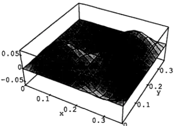
In Fig. 2, one ION concentrated load is applied at(0.27, 0.27) and the center of one PZT sensor /actuator pair is placed at(0.9, 0.9). The point source frequency is adjusted at the first resonance of the plate. Without the actuator, the response is as shown in Fig. 3. It shows the(l, 1) mode shape and has the maximum amplitude of 6 cm. When the control moment is coupled with the point load, the amplitude response changes to Fig. 4. Maximum amplitude reduces to 0.8 cm.
Figure 5 is the magnified view of the controlled vibration amplitude, which allows a clear view of the actuator effect. By means of oppositely sensed control moment, the peak at the source lo
cation decreases and a new downhill peak is generated at the actuator location. Figure 6 shows relative amplitude suppression ratios in terms of the decibel unit. There is a deep valley around the actuator. The valley corresponds to the points where the amplitude becomes almost zero after control. Maximum amplitude reduction is -90.7 dB at the valley and average reduction all over the plate surface is -24.7 dB. When the source frequency is tuned at the(l, 2) resonance of the plate, amplitude response without the con
troller is as in Fig. 7, and that with the controller is as in Fig. 8. Here also, at least around the ac
tuator, the curvature of the plate changes its sign after control Maximum amplitude suppression is -75.4 dB and average suppression is -23.1 dB.
When the source frequency is adjusted at the(2, 2)and (1, 3) resonance of the plate, similar results are obtained as in Figs. 9, 10 and Figs, 11, 12, respectively. Maximum amplitude reductions are 70.5 dB and -68.4 dB for each case, and occurs around the actuator position Average reductions are -28.0 dB and -15.0 dB, respect-
압전 센서와 액츄에이터를 이용한 단순지치 평판의 능동 진동제어-1. 이론 33
Fig 3. Vibration amplitude response of 나simply supported plate exposed to one point load tuned at(l,l) mode without any control ef
fect
Fig 6. Vibration amplitude reduction after 나冶 ac
tive vibration control when the plate is ex
posed to one point load tuned at (1,1) mode
Fig 4. Vibration amplitude response of the simply supported plate exposed to one point load tuned at(l,l) mode and one PZT sensor /ac
tuator pair
Fig 7. Vibration amplitude response of the simply supported plate exposed to one point load tuned at(l,2) mode without any control ef
fect
Fig 5. Magnified view of vibration amplitude response of the plate exposed to one point tuned at( 1.1) mode and one PZT sensor /actuator pair
Fig 8. Vibration amplitude response of the simply supported plate exposed to one point load tuned at(1.2) mode and one PZT sensor /ac tuator pair
34 韓國횮響學會誌 11 卷 3 號(1992)
Fig 9. Vibration amplitude response of the simply supported plate exposed to one point load tuned at(2,2) mode without any control ef
fect
Fig 12. Vibration amplitude response of the simply supported plate exposed to one point load tuned at(l,3) mode and one PZT sensor /ac
tuator pair
Fig 10. Vibration amplitude response of the simply supported plate exposed to one point load tuned at(2,2) mode and one PZT sensor /ac
tuator pair
Fig 13. Vibration amplitude response of the simply supported plate exposed to one point lo거d tuned at 30 rad. /sec. without any control effect.
댜g 11. Vibration amplitude response of the simply supported plate exposed to one point load tuned at(l,3) mode whithout any control ef feet
Fig 14. Vibration amplitude response of the simply supported plate exposed to one point load tuned at 3() rad. /ses. and one PZT sensor /actuator pair
압전 센서와 액츄에이터를 이용한 단순지지 평판의 능농 신동제어-1. 이론 35 ively. Higher modes of vibration can be analyzed
in the same fashion.
As seen in the results, the control efficiency of the sensor /actuator pair varies for each mode. It is because the fixed sensor /actuator position is not always good for all the modes of vibration.
Main idea employed in the analysis is to control the vibration by measuring and cancelling th- bending moment at a specific point of the struc
ture. The optimal location of the sensor and actu
ator for each mode should be therefore where the specific mode*s maximum bending moment occurs when the plate is loaded.
So far, the control element has controlled par
ticular modes of vibration. The controller could concentrate on that single mode, and the ef
ficiency was fairly good. If the exciting force is not tuned at the resonances of the plate, which is a more general case, the sensor / actuator pair has to control all the induced modes simultaneously, and the efficiency would deteriorate. Figures 13 and 14 show the uncontrolled and controlled vi
bration amplitude of the plate when the point load is applied at 30 radians /sec while (1, 1) res
onance frequency is 120 radians /sec. Maximum reduction is -43.4 dB and average reduction is -6.1 dB. The results confirm the above argument. Use of more control elements, each one aimed at specific modes, will improve the efficiency. In conclusion, these results verify the effectiveness of the Eq. 29.
4.1.2 m 니 ti 이 e point load and one PZT sensor/ actuator pair
Equation 29 is a general equation accommodat
ing arbirtary number of loads and sensor /actu
ator pairs. To check the validity of the equation for multiple number of external forces, three point loads are applied to the plate and one PZT sensor /actuator pair is used to control the vi
bration. External loads are located at (0.09, 0.27), (0.27. 0.09k(0.27, Q.27)and the sensor ^actuator pair 丄녕⑴MkR 勇 虬 Lql心"
lowered down to 2 N to prevent unrealistic vi bration. Source frequency tuned at the first res
onance of the plate produces the amplitude re sponse almost the same as Fig. 3. Figure 15
shows the vibration amplitude when the control effect is included. Effect of nearby two point loads is cancelled a lot, but that of the farther load at (0.27, 0.27) is still pronounced. Amplitude peak decreases from 4 cm to 0.8 cm. Maximum suppression occurs around the actuator and is -64.4 dB. Average reduction is -31.4 dB. For higher modes, similar results are obtained, and they are summarized m Table 2. Comparison of the two sets of data in Table 2 does not show much differece. That is because, even though the number of the point loads incre쇼ses, all of them are tuned at a certain frequency. The generated vibration mode does not have much distinct from that of a single point load. The increase of exter
nal loads requires more control effort, and it is taken care of by the control unit. In general, av
erage control efficiency decreases with the num
ber and distribution of the loads.
Table 2. Comparison of average vibration amplitude re
duction ratio mode one point load one
sensor /actuator pair
three point load one sensor /actuator pair
1, 1 -24.7 -31.4
1, 2 一 23.1 — 22.2
2, 2 -28.1 -24.2
1, 3 . -15.1 -14.1
unit : dB
4.1.3. one p 지 nt load and multi 미 e PZT sensor/ actuator pairs
This section investigates the case where the external point load is single, and the PZT sensor /actuator pair is multiple. When 10 N point load is adjusted at the first resonance, the vibration amplitude without control is the same as Fig. 3. With the three actuators turned on, the response diminishes to Fig. 16. Due to the increase of control forces, there is a great reduction in the ampiiiude. Maximum suppression is achieved around the load position as shown m Fig. 17 Res니Its for higher modes consideration are summarized in Table 3.
The case of multiple external forces and m냐 1-
36 韓國音響學會誌11卷3號(1992)
Fig 15. Vibr거tion amplitude response of the simply supported plate exposed to three point loads tuned at (1,1) mode and one PZT sensor /actuator pair
Fig 16. Vibration amplitude response of the simply supported plate exposed to one point load tuned at (1,1) mode and three PZT sensor /actuator pairs
Fig 17. Vibr거tion amplitude reduction after the ac
tive vibration control when the plate is ex
posed to one point load tuned at(l,l) mode
tiple control elements will be treated in Sec. 4.3
Table 3. Comparison of average viration amplitude re
duction ratio mode one point load one
sensor /actuator pair
one point load three sensor /actuator pairs
L 1 -24.7 -30.5
1, 2 -23.1 -24.2
2, 2 -28.1 -29.1
1, 3 -15.1 -17.1
unit : dB
4.2. Piezoelectric Drivers
Instead of the point load, the external load is given by a small PZT planar driver. The driver is basically the same as the actuator. Just the role of the element is different. When the plate is driven by the driver, the initial force is given in the form of bending monent like
mdxj = mdyj = Yd d3i(td+tp) Vd = rm. (34)
where Vu is driver electric voltage, td the thickness, and Yd the effective Young's mod냐his of the driver, respectiv이y. When the dimension of the piezoelectric driver is considered, the in
itial bending moment is given as
Mdxj =mdj[h(x — Xdji) -h(x —Xdj2) [h(y-ydji) -h(y-ydj2)],
Mdys=mdj [ h (x ~ xdj i) —h(x —Xdj2) (35) [h(y-ydji) -h(y-yd)2)].
These moments replace the forcing term F(xd, yd)in Eq. 12 as
CD 4 丄"* 02Mdxj I 泌Mdyj (36) DV4w-F/?w=^- ---1---
In the same manner as before, with Eq. 18, the coefficient aJnin is determined as
(mn)2 I (m)2
4m山 ( )
p ab(w^n-w2) 프프 I巫 a b Leos (m7gia
압전 센서와 액츄에이터를 이용한 단순지지 평판의 능동 진동제어 T. 이론 37
[cos (皿俨)-COS(虫臂)] (37)
The only difference between the point load and the PZT driver is the way of providing initiaPload to the plate. Point load is giving a direct force term as the P(xd, ya) in Eq. 12. and the PZT driver is giving a moment term. Generated vi bration of the plate should not change with re
spect to the way of receiving energy. In addition, the point load operates on just a single point. But the PZT driver operates on a planar area of the driver size even if small. This operation area can cause some difference in the control effort and the generation of higher modes of vibration. For the various arrangement of number and location of the drivers and controllers, however, results should be basically almost the same as those in Sec. 4.1. as long as the driver is not large. If we look at the case of one 1cm x 1cm PZT driver and one PZT sensor /actuator pair, the amplitude response shape is the same as Fig. 3 and 4. Am
plitude reduction ratio in Fig. 18 changes a little bit from that of Fig. 6 and this difference reflects the effect of exciter type change. Control results for the four modes are summarized in Table 4.
Table 4. Comparison of average vibration amplitude re
duction ratio
mode one point load one sensor /actuator pair
one PZT driver one sensor /actuator pair
1, 1 -24.7 -24.4
1, 2 -23.1 -23.3
2, 2 -28.1 -29.0
1, 3 -15.1 -16.1
unit : dB
Point Loads and Piezoelectric Drivers
Both point and PZT drivers are 닜sed as the initial external load source. and multiple pairs of PZT sensor /actuator are used as the control
Fig 18. Vibration amplitude reduction after the ac
tive vibration control when the plate is ex
posed to one PZT driver tuned mode
Fig 19. Vibration amplitude response of the simply supported plate exposed to one point load and one PZT driver, both tuned at(l,l) mode, as well as two PZT sensor /actuator pairs
Fig 20. Vibration amplitude reduction after the ac
tive vibration control when the plate is ex
posed to one point load and one PZT driver, both tuned at(l, 1) mode
38 韓國音響學會誌11卷3號(1992) elements. This corresponds to the case of mul
tiple external forces and multiple control elements. One 10 N point load is placed at (0.27, 27), 나le center of one 20 Nm PZT driver at(0.09, 0.27), and the centers of two PZT sensor /actu
ator pairs at(0.09, 0.09) and (0.27, 0.09), respect
ively. When both of the vibration sources are tuned at the first resonance of the plate. ampli
tude response. without the control effect is almost the same as Fig. 3. Figure 19 shows the response with the actuator on. Amplitude reduction ratio is described in Fig. 20. The figure clearly shows the external force dominating zone and the control moment dominating zone. Maximum amplitude suppression occurs around the actuator and is -90 dB. Average suppression is -26.4 dB.
Further results are summarized in Table 5.
These prove the validity of the Eq. 29 for mul
tiple input forces and multiple pairs of the piezoelectric sensor /actuator.
Table 5. Comparison of average vibration amplitude re
duction ratio
mode one point load one sensor /actuator pair
one point ]oad, one PZTdriver two sensor /actuator pair
1, 1 -24.7 -26,4
1, 2 -23.1 — 25.4
2, 2 -28.1 -23.5
1, 3 -15.1 -15.4
unit : dB
V. Conclusion
Theoretical aspects of active vibration control of a simply supported plate were investigated using piezoelectric sensors and actuators. Appropriate dynamic equations of the piezoelectric sensor and actuator for the control purpose were derived and coupled with the governing equation of the plate.
Analytic solution of the modified equation of mo
tion allows detailed analysis of the vibration am
plitude response of the plate to the combined ef
fect of external driving forces and piezoelectric
control moments. To illustrate the solution, nu
merical analysis was performed with concentrated point loads and PZT plate drivers. The results demonstrate the effectiveness of the solution as well as the piezoelectric sensors and actuators.
The approach investigated in this work can be applied to arbitrary external loading conditions and control algorithm. Experimental verification of the theoretical results will be presented next.
References
1. Proceedings of international symposium on active control of sound and vibration, Acoustical Society of Japan, Tokyo, Japan, May, 1991
2. J.L.Fanson and T.K.Caughey, "Positive position feedback control for large space structures", AIAA paper 87-0902, 1987
3. M.J.Balas, "Modal control of certain flexible dy
namic systems”,SIAM Journal of Control and Optimization, vol. 16, No. 3, pp. 450-462, 1978 4. D.B.Schaechter, uOptimal local control of flex-
urable structures," Journal of Guidance and Con
trol, vol. 4, No. 1. pp. 22-26, 1981
5. T.Bailey and J.E.Hubbard, “Distributed pie
zoelectric polyrper active vibration control of a cantilever beam," Journal of Guidance and Control, voL 8, No 8. pp. 605-611, 1985
6. B.A.Auld, Aco나Stic fields and waves in solids, vol.
1, John Wiley & Sons, New York, 1973
7. J.F.Nye. Physical properties of crystals, Oxford University Press, New York, 1985
8. Y.R.Roh, uActive vibration control with pie zoelectric sensors and actuators/ Proceedings of Kores-Japan joint symposium on acoustics, pp.
403-408, 1991
9. S.Timoshenko and S.Wonowsky-Krieger, Theory of plates and shells, McGraw Hill, New York, 1970 10. J.A.Nelder and R.Mead, “A simplex method for
function minimization". Computer Journal, vol. 7, pp. 308-312, 1965
압전 센서와 액츄에이터를 이용한 단순지지 평판의 능동 진동제어 …L 이론 39 Yongrae Roh received the B,
S. and M. S. degrees in Min
eral and Petroleum Engineer
ing from the Seoul National University, Seoul m 1984 and 1986, respectively. He got the Ph. D. degree in Engineering Science and Mechanicsfmajor in Acoustics) from the Pennsylvania State University, U. S. A., in 1990. He is currently a senior research scientist in the Research Institute of Industrial Science &
Technology, Pohang. Major research area includes SAW devices, ultrasonic transdeers, and noise & vibration control. He received the 1990 Xerox Award, U.S.A., for the best research in mater ials.